Table of Contents
Advertisement
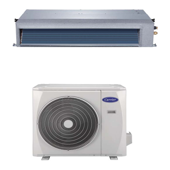
SLIM DUCTED AIR CONDITIONER
IMPORTANT NOTE:
Read this manual carefully before
•
installing or operating your new air
conditioning unit. Make sure to save
this manual for future reference.
This manual only describes the installation of
•
outdoor unit. When installing the indoor unit,
refer to the installation manual of indoor unit.
INSTALLATION MANUAL
42/38SHDS050
42/38SHDS070
42/38SHDS090
42/38SHDS100
Advertisement
Table of Contents

Related Manuals for Carrier 42/38SHDS050


Summary of Contents for Carrier 42/38SHDS050
-
Page 1: Installation Manual
SLIM DUCTED AIR CONDITIONER INSTALLATION MANUAL 42/38SHDS050 42/38SHDS070 42/38SHDS090 42/38SHDS100 IMPORTANT NOTE: Read this manual carefully before • installing or operating your new air conditioning unit. Make sure to save this manual for future reference. This manual only describes the installation of •... - Page 2 Table of Contents Installation Manual Accessories ............ Safety Precautions ........Installation Overview ....... Indoor Unit Installation ......a. Indoor Unit Parts ........b. Indoor Unit Installation Instructions ..08 Outdoor Unit Installation ......a. Outdoor Unit Installation Instructions ..12 b.
-
Page 3: Table Of Contents
Refrigerant Piping Connection ....... A. Notes on Pipe Length and Elevation ....17 B. Refrigerant Piping Connection Instructions ...18 Wiring ..........a. Outdoor Unit Wiring ....b. Indoor Unit Wiring ..... c. constant air flow control ..d. Power Specifications .... - Page 4 Accessories The air conditioning system comes with the following accessories. Use all of the installation parts and accessories to install the air conditioner. Improper installation may result in water leakage, electrical shock and fire, or cause the equipment to fail. NAME SHAPE QUANTITY...
- Page 5 Safety Precautions Read Safety Precautions Before Installation Incorrect installation due to ignoring instructions can cause serious damage or injury. The seriousness of potential damage or injuries is classified as either a WARNING or CAUTION. Failure to observe a warning may result in death. The appliance must be installed in accordance with national regulations.
- Page 6 Installation Overview INSTALLATION ORDER Install the indoor unit Install the outdoor unit Install the drainpipe (Page 7) (Page 13) (Page 15) Evacuate the refrigeration system Connect the wires Connect the refrigerant pipes (Page 25) (Page 20) (Page 17) Perform a test run (Page 27) Page 6...
-
Page 7: Indoor Unit Installation
Indoor Unit Installation Indoor Unit Parts Air inlet Electric control cabinet Air filter(on some models) Drain hose Air outlet Refrigerant connecting pipe Fig. 4.1 Safety Precautions CAUTION WARNING • Securely install the indoor unit on a structure • Install the indoor and outdoor units, cables that can sustain its weight. - Page 8 42SHDS050 42SHDS050 Step 2: Hang indoor unit. 1. Please refer to the following data to locate the four positioning screw bolt hole on the ceiling. Be sure to mark the areas where ceiling hook holes will be drilled. Dimension and air outlet size Air inlet size Air filter Position of descensional ventilation opening and size of mounted hook...
- Page 9 3. The installation of hanging screw bolts. Wooden construction Cut off the roof beam. Put the square timber traversely over the roof beam, then install the hanging screw bolts. (Refer Strengthen the place that has been cut off, to Fig.4-4) and consolidatethe roof beam.
- Page 10 Step 3: Duct and accessories installation 1. Install the filter(optional) according to air inlet size. 2. Install the canvas tie-in between the body and duct. 3. Air inlet and air outlet duct should be apart far enough to avoid air passage short-circuit. 4.
- Page 11 Step 4: How to adjust the air inlet direction? Step 5: Fresh air duct installation (From rear side to under-side.) Dimension : Duct joint for fresh air 1. Take off ventilation panel and flange . Air return flange MODLE 18-60 Ø125mm(4.92”) Ø160mm(6.3”) Ventilation panel...
- Page 12 Outdoor Unit Installation √ The area must be free of combustible gases Outdoor Unit Installation Instructions and chemicals. √ The pipe length between the outdoor and Step 1: Select installation location. indoor unit may not exceed the maximum The outdoor unit should be installed in the allowable pipe length.
- Page 13 (Refer to Fig 5.4, 5.5 and Table 5.1) (Refer to Fig 5.4, 5.5 and Table 5.1) Fig. 5.4 Fig. 5.5 Table 5.1: Length Specifications of Split Type Outdoor Unit (unit: mm/inch) Outdoor Unit Dimensions Mounting Dimensions Distance A Distance B W x H x D 350 (13.8) 845x702x363 (33.27x27.6x14.3)
- Page 14 NOTE: The minimum distance between the Notes On Drilling Hole In Wall outdoor unit and walls described in the You must drill a hole in the wall for the installation guide does not apply to airtight refrigerant piping, and the signal cable that will rooms.
-
Page 15: Drainpipe Installation
Drainpipe Installation The drainpipe is used to drain water from the NOTE ON DRAINPIPE INSTALLATION unit. Improper installation may cause unit and • When using an extended drainpipe, tighten property damage. the indoor connection with an additional protection tube to prevent it from pulling CAUTION loose. - Page 16 The unit with pump. 3. Using a 65-mm (2.5”) core drill, drill a hole in the wall. Make sure that the hole is drilled at 1. Remove the test cover, and stow about a slight downward angle, so that the outdoor 2000ml water to the water pan.
-
Page 17: Refrigerant Piping Connection
Refrigerant Piping Connection Safety Precautions Notes On Pipe Length and Elevation Ensure that the length of the refrigerant pipe, the number of bends, and the drop height between WARNING the indoor and outdoor units meets the • All field piping must be completed by a requirements shown in Table 7.1: licensed technician and must comply with the local and national regulations. -
Page 18: Refrigerant Piping Connection Instructions
Step2: Remove burrs. Refrigerant Piping Connection Instructions Burrs can affect the air-tight seal of refrigerant piping connection. They must be completely CAUTION removed. 1. Hold the pipe at a downward angle to The branching pipe must be installed • prevent burrs from falling into the pipe. horizontally. - Page 19 5. Clamp flare form on the end of the pipe. NOTE: Use both a spanner and a torque wrench The end of the pipe must extend beyond when connecting or disconnecting pipes to/from the flare form. the unit. Flare form Fig.
-
Page 20: Wiring
Wiring Follow these instructions to prevent distortion Safety Precautions when the compressor starts: • The unit must be connected to the main WARNING outlet. Normally, the power supply must • Be sure to disconnect the power supply have a low output impedance of 32 ohms. before working on the unit. -
Page 21: Indoor Unit Wiring
Table 8.2: Other Regions Indoor Unit Wiring Rated Current of Nominal Cross-Sectional 1. Prepare the cable for connection Appliance (A) Area (mm²) a. Using wire strippers, strip the rubber jacket from both ends of signal cable to reveal about 15cm (5.9”) of the wires inside. 25- 32 b. -
Page 22: Constant Air Flow Control
CONSTANT AIR FLOW CONTROL CAUTION DO NOT adjust the dampers during fan Using the wire controller to set external • operation for airflow automatic adjustment. static pressure. After 3 to 6 minutes, the air conditioning unit Settings for external static pressure can be •... -
Page 23: Power Specifications
Power Specifications NOTE: System power supply from outdoor unit. Page 23... - Page 24 Air Evacuation 4. Turn on the vacuum pump to evacuate the Safety Precautions system. 5. Run the vacuum for at least 15 minutes, or until the Compound Meter reads -76cmHG CAUTION (-1x10⁵Pa). 6. Close the Low Pressure side of the manifold •...
-
Page 25: Air Evacuation
Note On Adding Refrigerant CAUTION • Refrigerant charging must be performed after wiring, vacuuming and the leak test. DO NOT exceed the maximum allowable quantity of refrigerant or overcharge the system. • Doing so can damage or impact the unit’ s function. •... -
Page 26: Note On Adding Refrigerant
Test Run f. Check to see that the drainage system is Before Test Run unimpeded and draining smoothly. A test run must be performed after the entire g. Ensure there is no vibration or abnormal system has been completely installed. Confirm noise during operation.
Need help?
Do you have a question about the 42/38SHDS050 and is the answer not in the manual?
Questions and answers