
Related Manuals for Carrier 42/38KCJ024713


Summary of Contents for Carrier 42/38KCJ024713
- Page 1 Free Stand Air Conditioner Model: 42/38KCJ024713 42/38QCJ024713 42/38KCJ036813 42/38QCJ036813 42/38KCJ048813 42/38QCJ048813...
-
Page 2: Table Of Contents
Content CONTENT Safety Precautions ..................1 Precaution ........................1 Installation ........................1 Caution ..........................1 Operational........................1 Out Dimensions ....................3 Indoor Unit ........................3 Outdoor Unit ........................3 External view and display ................4 External view ........................4 Display panel ........................5 Refrigerant cycle diagram ................ -
Page 3: Safety Precautions
Safety Precautions 1 Safety Precautions 1.1 Precaution To prevent injury to the user or other people and property damage, the following instructions must be followed. Incorrect operation due to ignoring instruction will cause harm or damage. Before service unit, be sure to read this service manual at first. 1.2 Installation For electrical work, contact the dealer, seller, a qualified electrician, or an Authorized service center. - Page 4 Safety Precautions draft). Do not use the product for special purposes, such as preserving foods, works of art, etc. It is a consumer air conditioner, not a precision refrigerant system. Do not block the inlet or outlet of air flow. Use a soft cloth to clean.
-
Page 5: Out Dimensions
External view and display 2 Out Dimensions 2.1 Indoor Unit Width Height Depth (mm) (mm) (mm) 1700 1825 1825 2.2 Outdoor Unit Width Height Depth (mm) (mm) (mm) (mm) (mm) -
Page 6: External View And Display
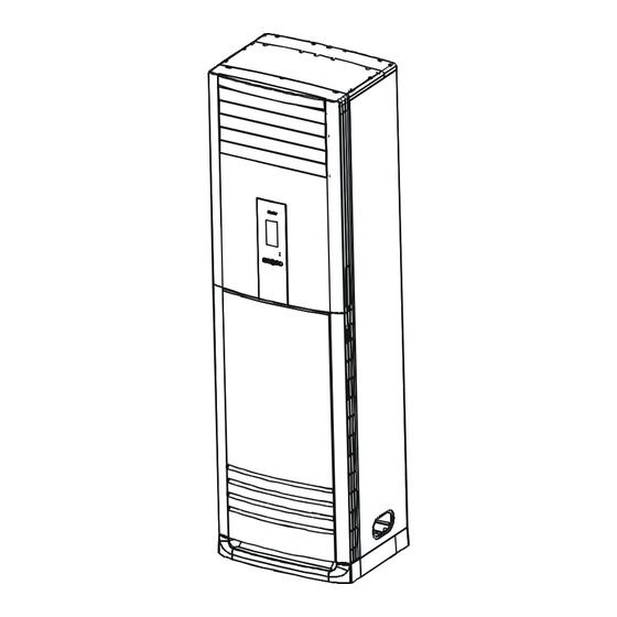
External view and display 3 External view and display 3.1 External view Outd oor unit Indoor unit Drain pipe, vent pip e Air out let Connect ion cable Operat ion panel Connect ion pipe Horizo nt al airf low cont rol louver Refrigerant pipe po rt Vert ic al airf low cont rol louver Air out let... -
Page 7: Display Panel
External view and display 3.2 Display panel... -
Page 8: Refrigerant Cycle Diagram
Refrigerant cycle diagram 4 Refrigerant cycle diagram 4.1 Cooling only 4.2 Heat pump model... -
Page 9: Pcb Drawing & Wiring Diagram
PCB drawing & Wiring diagram 5 PCB drawing & wiring diagram 5.1 42/38KCJ024713 Indoor unit Outdoor unit 5.2 42/38QCJ024713 Indoor unit... - Page 10 PCB drawing & Wiring diagram Outdoor unit 5.3 42/38KCJ036713 Indoor unit...
- Page 11 PCB drawing & Wiring diagram Outdoor unit 5.1 42/38QCJ036713 Indoor unit...
- Page 12 PCB drawing & Wiring diagram Outdoor unit 5.1 42/38KCJ048713 Indoor unit...
- Page 13 PCB drawing & Wiring diagram Outdoor unit 5.1 42/38QCJ048713 Indoor unit...
- Page 14 PCB drawing & Wiring diagram Outdoor unit...
-
Page 15: Installation Detail
Installation detail 6 Installation detail 6.1 Installation place 6.1.1 Indoor Unit A place which provides the spaces around the indoor unit as required above in the diagram. A place where is no obstacle near the inlet and outlet area. A place which can bear the weight of the indoor unit. A place which allows the air filter to be removed downward. -
Page 16: Installing
Installation detail 6.1.2.2 If the outdoor unit is to be installed on a roof or where no constructions are around, you should avoid hard wind blows directly to the air outlet, because it may cause trouble for air-flow shortage. 6.1.2.3 Reserve enough space for installation, maintenance and unit-functioning. Remove as many obstacles as possible nearby. - Page 17 Installation detail Pull down the two knobs on the grid, take off the two screws, then the air-inlet grid goes free. 6.2.3 Take the Pipe Clip off before connecting the pipes and wiring; fit it when these finished. Use accessories 4 and 9 to connect the pipes/wires on both sides and back side. Pipe/ wire-hole positions on both sides Drain Pipe Refrigerant Pipe...
-
Page 18: Refrigerant Pipe Connecting
Installation detail centralized; Do not make the angle of inclination more than 45 degrees while shipping;(Avoid horizontal storage) Be sure the electric insulation work is well done if installed on metal ceiling / wall. Fix the unit feet with bolts (M10/M8). Be sure the unit is fixed strongly enough to against blast or earthquake. - Page 19 Installation detail a. Only the correctly installing of indoor and outdoor unit done, can the refrigerant pipe be connected. b. The cut-off valves are completely close before ex-work. Before connecting the refrigerant pipe, be careful to check whether the valves are completely close. c.
-
Page 20: Drain Pipe Of The Indoor Unit
Installation detail 6180~7540N.cm(630~770kgf.cm) 9720~11860N.cm(990~12106kgf.cm) 6.3.3 Air Purging When Using the Vacuum Pump (For method of using a manifold valve, refer to its operation manual.) a. Completely tighten the flare nuts, A, B, C, D, connect the manifold valve charge hose to a charge port of the low-pressure valve on the gas pipe side. b. -
Page 21: Wiring
Installation detail of 0.03, at least 9 mm in thickness), and use Glue Band to fix it. After the Drain Pipe has been connected, please check if the water drains out of the pipe efficiently and has no leakage. Refrigerant pipe and Drainpipe should be heat-insulated to avoid condensing and water-dropping later on. -
Page 22: Electronic Function
Exploded view & spare-part 7 Electronic function 7.1 Performance Index Item Index Applicable Voltage Range 185-253V, 342-418V A/C Frequency 50Hz Working environment temperature -7° C- +45° C 7.2 Main data Introduction Ts : Set temperature, T1 : Room temperature T2: Evaporator pipe temperature 7.3 Operation Modes and Functions 7.3.1 Manual Operation 7.3.2 Heating Mode... -
Page 23: Cooling Mode
Exploded view & spare-part T2>32° C Set fan speed Room temperature down T2>22° C Set fan speed 20° C <T2<22° C T2<20° C 7.3.3 Defrost (only available to heating mode) 7.3.3.1 Defrosting Conditions Starting Of Defrosting Condition (meet one of the following is ok): (1)Accumulated compressor operating time when temperature of outdoor heat exchanger coil T3 is below -2°... -
Page 24: Other Functions
Exploded view & spare-part Room temperature down T1-Ts>1° C T1-Ts <1° C 7.3.5 Dehumidifying Mode 7.3.5.1 Indoor fan speed is low. 7.3.5.2 If certain protective condition is met, operation will be carried out. 7.3.6 Auto Mode 7.3.6.1 Under auto mode, the indoor fan is set to be auto. 7.3.6.2 When entering auto mode, the heating, fan only or cooling operation will be automatically chosen according to the room temperature T1 and the set temperature Ts. -
Page 25: Self-Diagnosis
Exploded view & spare-part At the beginning of energizing or after the stop of the compressor, 3-minute delay will be needed to start the compressor. When switching over between cooling/heating mode, the compressor stops automatically. 8.1.2 Evaporator protection against high temperature 8.1.2.1 Only available under heating mode. -
Page 26: Troubles And Solutions
Exploded view & spare-part Protection of defrosting or anti-cold wind Open-circuit and short-circuit of temperature sensors T1 Temp. sensor T2 on indoor evaporator is open circuit or short circuit The condenser temperature sensor T3 is open or short Protection of outdoor unit 8.2.1 LEDs for the indication of outdoor trouble In normal operation, LEDs emit no light and they will flash at a frequency of 5 Hz when trouble occurs. - Page 27 Exploded view & spare-part Be in 3 minutes protection of Wait compressor Number Display Problem What to do code E1 E2 E3 Temperature Sensor is off or Contact service people short-circuit. Outdoor unit protection Contact service people Electrostatic dust collection Contact service people Turn off the unit, clean the The temperature of the evaporator of...
Need help?
Do you have a question about the 42/38KCJ024713 and is the answer not in the manual?
Questions and answers