
Related Manuals for LONCIN G120F


Summary of Contents for LONCIN G120F
- Page 1 G120F/G160F/G200F Contents G120F·G160F·G200F Shop manual Loncin Motor Co., LTD - 1 -...
-
Page 2: Table Of Contents
G120F/G160F/G200F Contents Contents Part I specifications ······································································································ 3 Introduction······································································································· 3 Product parameters ·························································································· 4 Dimensions (boundary and mounting dimensions) ······································ 6 PTO assembly drawing ···················································································· 8 Wiring diagrams······························································································ 10 Part II Description of maintenance ············································································ 12 Safety precautions·························································································· 12 Maintenance standards ·················································································· 14 Torque values··································································································... - Page 3 G120F/G160F/G200F Contents Starter and control box ·················································································· 33 Carburetor ······································································································· 37 Fuel tank and speed governing system························································ 39 Flywheel, ignition coil, starter motor and lighting coil ································ 40 Cylinder head and valves ··············································································· 44 Crankcase body, piston, connecting rod and crankshaft ··························· 50 Governing gear and fuel level switch····························································...
-
Page 4: G120F/G160F/G200F
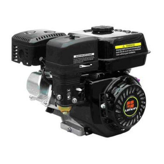
G120F/G160F/G200F Part I specifications 1-1.Introduction 1-2. Product parameters 1-3. Dimensions (boundary and mounting dimensions) 1-4. PTO assembly drawing 1-5. Wiring diagrams Introduction Fuel tank cap Fuel tank Throttle lever Muffler Engine switch Spark plug Air cleaner Choke lever Oil drain plug... -
Page 5: Product Parameters
G120F/G160F/G200F Part I specifications 1-2 Product parameters Engine model G120F G160F/ G160FD G200F/ G200FD Engine type Single cylinder, 4-Stroke, Forced Air Cooling, OHV25° Net power (KW/3600rpm) Net torque (N·m/rpm) 7.3/2500 9.9/2500 12.4/2500 Bore×stroke(mm) 60×42 68×45 68×54 Displacement (cc) Compression ratio 8.5:1... - Page 6 G120F/G160F/G200F Part I specifications Engine model G160F(D)-B G200F(D)-B G160F(D)-C G200F(D)-C Engine type Single cylinder, 4-Stroke, Forced Air Cooling, OHV25° Net power (KW/4000rpm) Net torque (N·m/rpm) 19.8/1250 24.8/1250 19.5/1250 24.8/1250 Power output mode Clutch Chain Reduction ratio 2:1 Bore×stroke(mm) 68×45 68×54 68×45...
-
Page 7: Dimensions (Boundary And Mounting Dimensions)
G120F/G160F/G200F Part I specifications 1-3 Dimensions (boundary and mounting dimensions) G120F - 6 -... - Page 8 G120F/G160F/G200F Part I specifications G160F/G200F - 7 -...
-
Page 9: Pto Assembly Drawing
G120F/G160F/G200F Part I specifications 1-4 PTO assembly drawing G120F/G160F/G200F To crankcase cover mount surface To crankcase cover mount surface A Type C Type To crankcase cover mount surface To crankcase cover mount surface R Type D Type - 8 -... - Page 10 G120F/G160F/G200F Part I specifications To crankcase cover mount To crankcase cover mount surface surface E Type S Type To crankcase cover mount surface To crankcase cover mount surface U Type A22 Type - 9 -...
-
Page 11: Wiring Diagrams
G120F/G160F/G200F Part I specifications 1-5 Wiring diagrams Wire colors and codes Combination switch Black Brown ○ ○ Yellow White Green ○ ○ START With oil alert and electric starter Starter motor Battery Starter solenoid Charging coil Bl/W Fuse Rectifier Engine switch... - Page 12 G120F/G160F/G200F Part I specifications With oil alert and without electric starter Ignitor Engine switch Spark plug Oil level switch Oil alert unit - 11 -...
-
Page 13: Part Ii Description Of Maintenance
LONCIN products products disassembly. Lubricate sliding designated by Loncin surfaces before reassembly. 2. Work to be done with special tools must 6. After reassembly, check all parts for be done with such tools. proper installation and operation. 7. Don’t maintain unless the engine is stopped and has cooled, otherwise, bun 3. - Page 14 G120F/G160F/G200F Part II Description of maintenance 9. Self-tapping bolts (capable of tapping 10. Joint seams of the fuel tank are joined while being screwed in) are used for with adhesive, if you use local welding, some portions of the engine; take care the hot temperature may cause adhesive not to damage their threads.
-
Page 15: Maintenance Standards
G120F/G160F/G200F Part II Description of maintenance 2-2 Maintenance standards G120F G120F Part Item Standard Service limit 3850±150rpm Engine Maximum speed Cylinder Cylinder bore 60.0mm 60.165mm Warpage 0.10mm Cylinder head Skirt OD 59.985mm 59.845mm Piston-to-cylinder clearance 0.015-0.050mm 0.12mm Piston Piston pin bore ID 13 .002mm... - Page 16 G120F/G160F/G200F Part II Description of maintenance G160F/G200F G160F/G200F Part Item Standard Service limit 3850±150rpm Engine Maximum speed Cylinder Cylinder bore 68.0mm 68.165mm Warpage 0.10mm Cylinder head Skirt OD 67.985mm 67.845mm Piston-to-cylinder clearance 0.015-0.05mm 0.12mm Piston pin bore ID 18 .002mm 18.048mm...
-
Page 17: Torque Values
G120F/G160F/G200F Part II Description of maintenance 2-3 Torque values G120F/G160F/G200F Item Thread dia.×pitch Tightening torque (N·m) Connecting rod bolt M7×1 12-14 Cylinder head bolt M8×1.25 32-35 Flywheel bolt M14×1.5 80-90 Valve lock nut M6×0.75 12-16 Valve adjusting bolt M8×1.25 26-32 M6×1(G120F) -
Page 18: Troubleshooting
G120F/G160F/G200F Part II Description of maintenance 2-4 Troubleshooting Fuel filter clogged Clean P27(3-6) 1. General symptoms possible causes Readjust P29(3-8) Disassemble and inspect Carburetor faulty P37(4-3) Readjust P40(4-5) Ignition coil air gap incorrect Hard starting Ignition coil faulty Inspect P40(4-5)... - Page 19 G120F/G160F/G200F Part II Description of maintenance 2. Hard starting ●Add fuel and restart the engine ①Check the fuel level in the No fuel tank Sufficient fuel ● Check for blockage of the fuel tube or fuel filter ● Check for blockage in the carburetor ②Remove the spark plug and...
- Page 20 G120F/G160F/G200F Part II Description of maintenance 3. Troubleshooting with oil alert unit installed on the engine Remove the spark plug engine switch and check with a new ● Fault of other part than oil alert unit position spark plug. Good spark engine doesn’t...
- Page 21 G120F/G160F/G200F Part II Description of maintenance 4. Troubleshooting for no spark plug at spark plug Good Check spark plug Check with spark Replace igniting state. Starting spark plug Spark plug gap: poor spark plug 0.7-0.8mm spark ●Refer to the part...
- Page 22 G120F/G160F/G200F Part II Description of maintenance 5. Troubleshooting for hard electric starting Combination switch is open or Starter motor Inspect P33 (4-2) doesn’t rotate faulty Replace Fuse melted Inspect P40 (4-5) Starter solenoid faulty Inspect P40 (4-5) Starter motor faulty...
-
Page 23: Part Iii Maintenance
* Replace foam and paper elements only (1) Service more frequently when used in the dusty areas. (2) These items are to be maintained by Loncin’s designated dealers unless the user has special tools and skills for maintenance. When the engine is used frequently, only maintenance as per the above schedule can ensure long and normal performance of the engine. -
Page 24: Engine Oil
In order to obtain the best performance of the engine, it is recommended to use special engine oil certified to be OK for Loncin engines. SAE 10W-30 is the recommended oil. Other viscosities shown in the chart may be used when the average temperature in your area is within the recommended range. -
Page 25: Oil Alert System Inspection
G120F/G160F/G200F Part III Maintenance ·Please dispose of used engine oil and the oil containers in a manner that is compatible with the environment. We suggest that you take it in a sealed container to your local waste disposal site or service station for reclamation. Do not throw it in the trash;... -
Page 26: Air Cleaner
G120F/G160F/G200F Part III Maintenance 3-4 Air cleaner A dirty air filter will restrict fair flow to the carburetor, reducing engine performance. If the engine is operated in dusty areas, clean the air cleaner more often than specified in the MAINTENANCE SCHEDULE. -
Page 27: Muffler
G120F/G160F/G200F Part III Maintenance 6) Place the foam air filter element over the paper element, and reinstall the assembled air filter. Be sure the gasket is in place beneath the air filter; then tighten the wing nut securely. 7) Install the air cleaner cover and tighten the wing nut securely. -
Page 28: Fuel Filtering System
G120F/G160F/G200F Part III Maintenance Never use iron wires to clean the muffler, or the sound insulation,or the acoustical absorbing material will be scraped away and muffler’s performance will be lowered. Reassembly: Muffler’s seal washer cannot be used repeatedly. Gently knock with a pastic hammer to... -
Page 29: Spark Plug
G120F/G160F/G200F Part III Maintenance Spark plug wrench 3-7 Spark plug Recommended types: F7RTC or equivalent types. Spark plugs of the wrong type can lower engine performance and cause engine damage 1) Remove the spark plug cap. 2) Remove the spark plug with a spark plug wrench. -
Page 30: Carburetor (Idle Speed)
G120F/G160F/G200F Part III Maintenance 3-8 Carburetor (idle speed) Throttle stop screw 1) Start the engine and allow it to warm up for about 10 minutes. 2) Set the throttle lever in the position for lowest speed. 3) Use tools to adjust the throttle stop screw, to bring the idle speed within the range of standard idle speed. -
Page 31: Governor
G120F/G160F/G200F Part III Maintenance 3-10 Governor Governor arm Governor spring Governor limit spring Throttle return spring ×35 Governor rod Screw M5 Control lever 1) Remove the fuel tank. 2) Loosen the hexagon flange nut (M6) of the pointless lag lock screw to move the governor arm to fully open the throttle. -
Page 32: Part Iv Disassembly And Maintenance
G120F/G160F/G200F Part IV Disassembly and maintenance 4-1. Air cleaner and muffler 4-2. Starter and control box 4-3. Carburetor 4-4. Fuel tank and speed governing system 4-5. Flywheel, ignition coil, starter motor and lighting coil 4-6. Cylinder head and valves 4-7. Crankcase body, piston, connecting rod and crankshaft 4-8. - Page 33 G120F/G160F/G200F Part IV Disassembly and maintenance 2. Disassembly/reassembly of muffler M5×8mm cross Muffler protector recessed pan head screw(4) 8mm hexagon nut(2) 2.4kg-m Muffler Reassembly: Install after removing the carbon Exhaust pipe gasket deposits from the muffler by gently knocking with a plastic hammer.
-
Page 34: Starter And Control Box
G120F/G160F/G200F Part IV Disassembly and maintenance 4-2. Starter and control box 1. Disassembly/reassembly of starter Recoil starter Reassembly: Remove dirt and debris before installation. The installation direction can be changed by changing the relative positions of the holes in recoil starter case. - Page 35 G120F/G160F/G200F Part IV Disassembly and maintenance Reassembly steps 1) Wind the spring into the cover and hook Return spring spring’s outer hook to the notch of the spring cover. Spring cover 2) Align the spring’s outer hook with reel’s groove, and install the cover onto the reel.
- Page 36 G120F/G160F/G200F Part IV Disassembly and maintenance 5) Feed the rope through the starter case hole and the Starter case hole starter grip; then make a figure eight knot at the rope end. Grip M5×10 special bolt 6) Assemble the ratchets and then tighten them with...
- Page 37 G120F/G160F/G200F Part IV Disassembly and maintenance 2. Disassembly/reassembly of control box (optional) 1. Disassembly/reassembly Black wire Black wire Black/white wire Connected Unidirectional Connected ignition coil’s stop conductional relay’s excitation switch wire device winding Overload White wire protector Start control Connected...
-
Page 38: Carburetor
G120F/G160F/G200F Part IV Disassembly and maintenance 4-3. Carburetor 1. Removal / disassembly No smoking or fire Carburetor heat insulating gasket Anti surge spring Governor Reassembly: Blow out the passage using compressed air and install, noting the inatllation directions on inner and Fuel tube outer sides. - Page 39 G120F/G160F/G200F Part IV Disassembly and maintenance 2. Disassembly/reassembly ·Before assembly, loosen the drain screw and drain the carburetor completely and keep heat, spark and flame away. Carburetor body Pilot jet Reassembly: Blow out the passage using Pilot screw compressed air and install.
-
Page 40: Fuel Tank And Speed Governing System
G120F/G160F/G200F Part IV Disassembly and maintenance 4-4. Fuel tank and speed governing system Disassembly/reassembly Gasoline is highly flammable and explosive, keep smoking, spark and flam away, and drain the fuel tank completely before removal and disassembly. Fuel tank cap Fuel tank... -
Page 41: Flywheel, Ignition Coil, Starter Motor And Lighting Coil
G120F/G160F/G200F Part IV Disassembly and maintenance 4-5. Flywheel, ignition coil, starter motor and lighting coil 1. Disassembly/reassembly Flywheel Starter motor Black wire Disassembly: Reassembly: insert Disassembly/reassembly:P.46 special tool, namely securely into the 2 ribs on flywheel puller to remove it, the crankcase never use hammer to tap it. - Page 42 G120F/G160F/G200F Part IV Disassembly and maintenance 2. Adjustment of ignition coil air gap 1) Insert a thickness gauge or a piece of paper of the same thickness between the ignition coil and flywheel. 2) Push the ignition coil firmly toward the flywheel by hand and tighten the bolt.
- Page 43 G120F/G160F/G200F Part IV Disassembly and maintenance 2) Lighting coil Measure resistance between the two leads. Resistance value 6V-15W 0.21~0.27Ω 6V-25W 0.09~0.15Ω 1.24~1.44Ω 12V-15W 0.36~0.46Ω 12V-25W 0.18~0.23Ω 12V-50W 3) Charging coil Measure resistance between the two leads. Resistance value 3.15-3.85Ω 4. Starter relay Disconnect negative of battery, and disconnect electromagnetic relay’s S terminal plug, and...
- Page 44 G120F/G160F/G200F Part IV Disassembly and maintenance 5. Starter motor 1) Brush length Check brush length and replace it if it is shorter than service limit due to wear. Service limit Standard 6.0 mm 11.0 mm 2) Continuity between commutator segments...
-
Page 45: Cylinder Head And Valves
G120F/G160F/G200F Part IV Disassembly and maintenance 4-6. Cylinder head and valves 1. Removal/installation Spark plug Cylinder head Reassembly: Reassembly: Clean adjust Before installing, remove spark plug before any carbon deposits from installation. Gasket Cylinder head the combustion chamber Gasket and inspect valve seats. - Page 46 G120F/G160F/G200F Part IV Disassembly and maintenance 2. Disassembly/reassembly Exhaust valve Intake valve Reassembly: Reassembly: Valve rotator Before installation, Do not interchange remove carbon deposits Reassembly: with exhaust valve or and inspect for damage If the valve retainer damage valve stem.
- Page 47 G120F/G160F/G200F Part IV Disassembly and maintenance 3. Inspection/maintenance/reconditioning: 1) Valve stem O.D Measure valve stem O.D With a millimeter if it’s smaller than the standard value or the service limit, or valve face has visible ablation or cracks, replace the valve.
- Page 48 G120F/G160F/G200F Part IV Disassembly and maintenance a) Check whether valve guide inner surface is smooth and flat, whether there is any scratch or drag mark on it; whether valve guide fits firmly with cylinder head. b) Ream the valve guides to remove any carbon deposits before measuring.
- Page 49 G120F/G160F/G200F Part IV Disassembly and maintenance Guide a) Coat the reamer and valve guide with cutting oil. Valve clip guide Rotate the reamer clockwise through the valve guide the driver full length of the reamer. Continue to rotate the reamer clockwise while removing it Guide from the valve guide.
- Page 50 G120F/G160F/G200F Part IV Disassembly and maintenance c) Use a 45°cutter, remove enough material to produce a smooth and concentric seat. Turn the cutter clockwise, Valve lapper never counterclockwise. Tool: valve lapper IN: 32° d) Use the 32°-45° and 60° cutter to narrow and adjust EX: 32°...
-
Page 51: Crankcase Body, Piston, Connecting Rod And Crankshaft
G120F/G160F/G200F Part IV Disassembly and maintenance -7. Crankcase body, piston, connecting rod and crankshaft 1. Diassembly/reassembly Camshaft assy Piston Reassembly: Check that the decompressor weight Reassembly: moves smoothly and the spring is not Install with weak or worn, then align the triangle... - Page 52 G120F/G160F/G200F Part IV Disassembly and maintenance 2. Piston/piston rings Reassembly: Install all rings with the markings facing upward Be sure that the top and second rings are not interchanged. Check that the rings rotate smoothly after installation. Space the piston ring end gaps 120 degrees apart and do not...
- Page 53 G120F/G160F/G200F Part IV Disassembly and maintenance Timing mark alignment Crankshaft Align the punch marks on the camshaft gear and Timing marks Camshaft timing gear (smaller gear on the crankshaft) when installing camshaft. 3. Inspection Piston inspection Check the contact between piston and cylinder, defects of ring grooves, ablation and cracks on piston top, etc.
- Page 54 G120F/G160F/G200F Part IV Disassembly and maintenance 3) Piston ring side clearance When inspecting put rings in the corresponding piston grooves and they should be able to rotate freely without looseness or stickiness. Then put a feeler gauge between the ring and groove’s upper or lower surface to measure.
- Page 55 G120F/G160F/G200F Part IV Disassembly and maintenance 7) Piston pin bore I.D. Standard Service limit G120 13.002mm 13.048 mm G160 200 18.002mm 18.048 mm 8) Piston pin-to-piston pin bore clearance Measure piston pin bore I.D. with an inside micrometer and piston pin O.D. with an outside micrometer. Then calculate the clearance using the measured values.
- Page 56 G120F/G160F/G200F Part IV Disassembly and maintenance Service limit Standard G120 13.07 mm 13.005mm G160 200 18.002mm 18.07 mm 2) Big end I.D. Replace the connecting if its big end I.D. is smaller than standard value or is out of service limit.
- Page 57 G120F/G160F/G200F Part IV Disassembly and maintenance d) If the clearance exceeds the service limit, replace the connecting rod and recheck the clearance. if the clearance after installing the new connecting still exceeds the service limit, ap the neck journal and use a connecting rod lower than the standard value.
- Page 58 G120F/G160F/G200F Part IV Disassembly and maintenance 3) Camshaft holder ID Standard Service limit 14.0mm 14.048mm Inspection of bearings Play Play Clean the bearing in solvent and dry it. Spin the bearing by hand and check for play. Replace the bearing if it is noisy or has excessive play.
-
Page 59: Governing Gear And Fuel Level Switch
G120F/G160F/G200F Part IV Disassembly and maintenance 4-8. Governing gear and fuel level switch 1. Disassembly/reassembly Governor weight Clip Reassembly: Reassembly: Check that the weights Governor gear Securely fix it in the move freely after groove Reassembly: Governor slider installation. Before installing, check... - Page 60 G120F/G160F/G200F Part IV Disassembly and maintenance 2. Inspection Oil level switch 1) Hold the oil level switch upside down to confirm there no continuity between yellow lead and ground wire. 2) Hold the oil level switch in its normal position, confirm the continuity exists between the yellow lead and ground wire.
-
Page 61: Reduction System
G120F/G160F/G200F Part IV Disassembly and maintenance 4-9. Reduction system 1. 1/2 reduction (with centrifugal clutch) Clutch friction disc Inspection: P.60(4-9 Clutch cover Reassembly: Reassembly: Note the installation Chain When installing it Clutch plate sequence. to the crankshaft, Inspection:P65 slot of the... - Page 62 G120F/G160F/G200F Part IV Disassembly and maintenance 2. 1/2 chain type Reduction cover Reassembly: Drive sprocket Take care not Reassembly: Check the sprocket teeth for damage the oil seal wear or damage for wear or M8×32(6) when inserting the damage before installing.
- Page 63 G120F/G160F/G200F Part IV Disassembly and maintenance 3. Inspection 1) Clutch friction disc Standard Service limit 3.0mm 3.5mm 2) Clutch plate Check the clutch plate warpage on a flat plate using a feeler gauge. - 62 -...
-
Page 64: Battery
G120F/G160F/G200F Part IV Disassembly and maintenance 4-10. Battery (optional) Use a battery rated at 12V, 18AH or more. Do not reverse polarity. Serious damage to the generator 上 刻 线 and/or battery may occur. Upper mark 下 刻 线 Lower mark Check the electrolyte level to be sure that it is between the marks on the case.
Need help?
Do you have a question about the G120F and is the answer not in the manual?
Questions and answers