Table of Contents
Advertisement
WIRELESS 868 MHz WEATHER STATION
Instruction manual
INTRODUCTION:
Congratulations on purchasing this innovative 868 MHz Weather Station which displays the
weather forecast, time, indoor temperature and up to three outdoor temperature readings.
To enjoy the full benefits of this innovative product, please read this operating manual.
46
Advertisement
Table of Contents

Related Manuals for La Crosse Technology WS9132


Summary of Contents for La Crosse Technology WS9132
- Page 1 WIRELESS 868 MHz WEATHER STATION Instruction manual INTRODUCTION: Congratulations on purchasing this innovative 868 MHz Weather Station which displays the weather forecast, time, indoor temperature and up to three outdoor temperature readings. To enjoy the full benefits of this innovative product, please read this operating manual.
- Page 2 The Weather Station Hanging hole Battery compartment Display Foldout Stand Function keys FEATURES: DCF Radio controlled time with manual setting option • • Time reception ON/OFF (user selectable) 12/24 hour time display • • Time zone option ±12 hours Calendar display (day and month) •...
- Page 3 • Weather forecasting with weather tendency indicator Indoor comfort indicator • • Temperature display in ºC/ºF Indoor and outdoor temperature display with MIN/MAX records and time of reception • • Indoor humidity display as RH% with MIN/MAX records Weather icon sensitivity setting •...
- Page 4 The Outdoor Temperature Transmitter Remote transmission of outdoor temperature to • Weather Station by 868 MHz signals Dual channel transmitter*: one internal channel • and one probe channel Shower proof casing • Wall mounting and table stand • This socket is only for the external probe.
- Page 5 Once the transmitter is successfully recognized by the Weather station, Channel 1 of the Weather station will display the temperature data measured by internal sensor and Channel 2 will display the temperature estimated by the probe. If the measuring probe is unplugged, the "probe channel" on Weather station (Channel 2) will show "---", yet the data from the internal sensor will still be shown on Channel 1 .
- Page 6 After the batteries are inserted, the Weather Station will start receiving data signal from the transmitter. If the optional probe has been plugged to the dual channel transmitter, the outdoor temperature should then be displayed on the Weather Station on channel 1 and 2. Also, the signal reception icon will be displayed.
- Page 7 Within 30 seconds of powering up the first transmitter, insert the batteries into the Weather Station. Once the batteries are in place, all segments of the LCD will light up briefly. Then the indoor temperature and the time as 0:00 will be displayed. If they are not shown on the LCD after 60 seconds, remove the batteries and wait for at least 60 seconds before reinserting them.
- Page 8 will display the data measured by the internal sensor of the second dual channel transmitter. Yet the probe data from the second transmitter will not be displayed on the Weather Station. Once the remote temperature has been received and displayed on the Weather Station, the DCF time code reception is automatically started.
- Page 9 INSTALL AND REPLACE BATTERIES IN THE WEATHER STATION The Weather Station uses 2 x AA, IEC LR6, 1.5V batteries. To install and replace the batteries, please follow the steps below: Insert finger or other solid object in the space at the bottom center of the battery compartment and lift up to remove the cover.
- Page 10 Remove the battery compartment cover. Insert the batteries, observing the correct polarity (see marking). Replace the battery compartment cover. Note: In the event of changing batteries in any of the units, all units need to be reset by following the setting up procedures. This is because a random security code is assigned by the transmitter at start-up and this code must be received and stored by the Weather Station in the first 3 minutes of power being supplied to it...
-
Page 11: Battery Change
BATTERY CHANGE: It is recommended to replace the batteries in all units regularly to ensure optimum accuracy of these units (Battery life see Specifications below). Please participate in the preservation of the environment. Return used batteries to an authorized depot. DCF RADIO CONTROLLED TIME The time base for the radio controlled time is a Cesium Atomic Clock operated by the Physikalisch Technische Bundesanstalt Braunschweig which has a time deviation of less... - Page 12 Once the outdoor reception test period is completed, the DCF tower icon in the clock display will start flashing in the upper center. This indicates that the clock has detected that there is a radio signal present and is trying to receive it. When the time code is received, the DCF tower becomes permanently lit and the time will be displayed.
-
Page 13: Function Keys
FUNCTION KEYS: Weather Station: The Weather Station has 4 easy to use function keys: CH key SET key IN key OUT key SET key Press and hold the key to enter manual setting modes: LCD contrast, time zone, time • reception ON/OFF, 12/24 hour display, manual time setting, calendar, temperature °C/°F and weather icon sensitivity setting IN key... - Page 14 • Reset the indoor MIN/MAX records OUT key • Press shortly to toggle between MAX/MIN and current outdoor temperature data Make adjustment in manual setting mode • • Reset the outdoor MIN/MAX records CH key Exit the manual set mode •...
-
Page 15: Lcd Screen
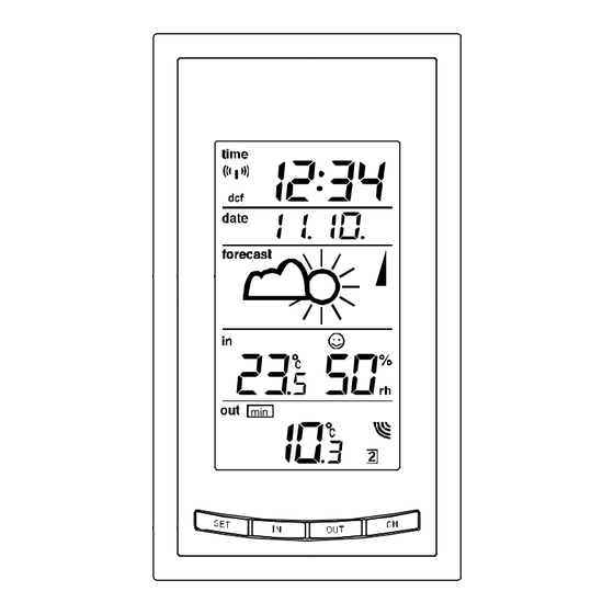
LCD SCREEN: Time reception icon Time (for DCF time) Calendar display Weather tendency indicator Weather forecast icon Low battery indicator Comfort indicator (weather station) icon Indoor relative Indoor temperature in ºC/ humidity in RH% ºF Low battery indicator (transmitter) Outdoor temperature in ºC/ Outdoor data signal ºF reception indicator*... -
Page 16: Manual Settings
*When the signal from the transmitter is successfully received by the Weather Station, this icon will be switched on. (If not successful, the icon will not be shown on the LCD). User can therefore easily see whether the last reception was successful (“ON” icon) or not (“OFF” icon). -
Page 17: Lcd Contrast Setting
Press and hold the SET key for about 3 seconds to advance to the setting mode: LCD CONTRAST SETTING flashing The LCD contrast can be set to 8 different levels (0 to 7) to suit the user’s needs (default LCD contrast setting is LCD 5). To set the desired contrast level: The above display will be seen. -
Page 18: Time Reception On/Off Setting
The time zone default of the Weather Station is 0 hr. To change to another time zone: Using the IN key to set the time zone. The range runs between -12 to +12 hour. Press the SET key to confirm and enter the “Time reception On/Off setting” or exit the setting mode by pressing the CH key. -
Page 19: 12/24 Hour Time Display Setting
Note: If the Time Reception function is turned OFF manually, the clock will not attempt any reception of the DCF time as long as the Time Reception OFF function is activated. The Time Reception icon will not be displayed on the LCD. 12/24 HOUR TIME DISPLAY SETTING flashing After setting time reception ON/OFF, press the SET key, “12 h”... -
Page 20: Manual Time Setting
date" display. MANUAL TIME SETTING In case the Weather Station is not able to detect the Atomic time (DCF) signal (disturbances, transmitting distance, etc.), the time can be manually set. The clock will then work as a normal Quartz clock. Hours (flashing) Minutes (flashing) To set the clock:... -
Page 21: Calendar Setting
CALENDAR SETTING Year "Date. Month." (for 24h time display) "Month. Date." (for 12h time display) The date default of the Weather station is 1. 1. of the year 2006 after initial set-up. Once the radio-controlled time signals are received, the date is automatically updated. However, if the signals are not received, the date can also be set manually. -
Page 22: C/°F Temperature Unit Setting
Confirm the day and month by pressing the SET key shortly once. Then the digit "10" will be displayed and flashing. User shall just press the SET key once more to enter the “°C/°F TEMPERATURE UNIT SETTING” or exit the setting mode by pressing the CH key. - Page 23 WEATHER FORECASTING ICON SENSITIVITY SETTING: Digit flashing For locations with rapid changes of weather conditions, the weather icons sensitivity can be set to a different level for faster display of weather conditions. The current sensitivity value will start flashing. Use the IN key to set the weather sensitivity level. There are 3 levels of setting: 1, 2 and 3.
- Page 24 WEATHER FORECAST AND WEATHER TENDENCY: WEATHER FORECASTING ICONS: Weather icons in the third section of LCD can be displayed in any of the following combinations: Cloudy with sunny Rainy Sunny intervals For every sudden or significant change in the air pressure, the weather icons will update accordingly to represent the change in weather.
- Page 25 cloudy and the rainy icon is displayed, it does not mean that the product is faulty because it is not raining. It simply means that the air pressure has dropped and the weather is expected to get worse but not necessarily rainy. Note: After setting up, readings for weather forecasts should be disregarded for the next 12-24 hours.
-
Page 26: Weather Tendency Indicator
mistake the new location as being a possible change in air-pressure when really it is due to the slight change of altitude. WEATHER TENDENCY INDICATOR Weather tendency indicator Working together with the weather icons is the weather tendency indicators (located on the right sides of the weather icons). - Page 27 Note: Once the weather tendency indicator has registered a change in air pressure, it will remain permanently visualized on the LCD. THE COMFORT LEVEL INDICATOR: Comfortable A happy face icon “☺” indicating a temperature level between 20°C and 25.9°C and relative humidity reading between 45% and 65%. Uncomfortable A sad face icon “...
- Page 28 MIN icon Indoor relative Indoor temperature humidity in RH% in °C or ºF TOGGLING AND RESETTING THE INDOOR READINGS: Press the IN key to toggle between the indoor current, indoor MAX/MIN temperature and indoor humidity data. The time and dates of the recorded data will also be displayed in the time and calendar sections (for temperature data only).
- Page 29 Time and date of recording the MIN temperature MIN Icon MIN Indoor MIN Indoor relative humidity temperature Once the MIN or MAX data is displayed, press and hold the IN key for 3 seconds to reset the respective MIN or MAX record to current temperature and humidity data, and to current time and date.
-
Page 30: Outdoor Temperature
OUTDOOR TEMPERATURE The fifth LCD section shows the outdoor temperature, the reception indicator, the transmitter identification number and the MIN/MAX outdoor data. Outdoor icon Outdoor temperature in Outdoor transmitter °C/ °F identification number TOGGLING AND RESETTING THE OUTDOOR DATA Press the OUT key to toggle between the outdoor current, outdoor MIN temperature, and outdoor MAX temperature and the times (for temperature data only): Press once to show the MIN outdoor temperature data with the recorded time and date. - Page 31 Press twice to show the MAX outdoor temperature data with the recorded time and date. Press three times to return to the current displayed values. Time and date of recording the MAX temperature MAX Icon MAX Outdoor temperature...
-
Page 32: About The Outdoor Transmitter
Once the MIN or MAX data is displayed, press and hold the OUT key for 3 seconds to reset the respective MIN or MAX record to current temperature data, and current time, date display. Note: The MIN/MAX data of different channels needs to be reset individually. ABOUT THE OUTDOOR TRANSMITTER The outdoor temperature is measured and transmitted every 4 seconds. - Page 33 Using other electrical products such as headphones or speakers operating on the same signal frequency (868MHz) may prevent correct signal transmission and reception. Neighbours using electrical devices operating on the 868MHz signal frequency can also cause interference. Note: When the 868MHz signal is received correctly, do not re-open the battery cover of either the transmitter or Weather station, as the batteries may spring free from the contacts and force a false reset.
- Page 34 To wall mount Choose a sheltered place. Avoid direct rain and sunshine. Before wall mounting, please check that the outdoor temperature values can be received from the desired locations. Fix a screw (not supplied) into the desired wall, leaving the head extended out the by about 5mm.
- Page 35 Free standing With the foldout stand, the weather station can be placed onto any flat surface.
- Page 36 POSITIONING THE TEMPERATURE TRANSMITTER: The Transmitter is supplied with a holder that may be attached to a wall with the two screws supplied. The Transmitter can also be position on a flat surface by securing the stand to the bottom to the Transmitter.
- Page 37 To wall mount: 1. Secure the bracket onto a desired wall using the screws and plastic anchors. 2. Clip the remote temperature sensor onto the bracket. Note: Before permanently fixing the transmitter wall base, place all units in the desired locations to check that the outdoor temperature reading is receivable.
-
Page 38: Care And Maintenance
CARE AND MAINTENANCE: Extreme temperatures, vibration and shock should be avoided as these may cause • damage to the unit and give inaccurate forecasts and readings. When cleaning the display and casings, use a soft damp cloth only. Do not use •... - Page 39 resolution); “OF.L” displayed if outside this range Relative humidity measuring range: Indoor 1% to 99% with 1% resolution (displays “- -” when lower than 1 %; displays "99" % if higher than 99 %) Indoor temperature checking interval : every 10 seconds Indoor humidity checking interval every 15 seconds Outdoor data reception...
-
Page 40: Liability Disclaimer
LIABILITY DISCLAIMER: The electrical and electronic wastes contain hazardous substances. Disposal of • electronic waste in wild country and/or in unauthorized grounds strongly damages the environment. Please contact your local or/and regional authorities to retrieve the addresses of legal • dumping grounds with selective collection. - Page 41 manufacturer. R&TTE Directive 1999/5/EC Summary of the Declaration of Conformity : We hereby declare that this wireless transmission device does comply with the essential requirements of R&TTE Directive 1999/5/EC.
Need help?
Do you have a question about the WS9132 and is the answer not in the manual?
Questions and answers