Table of Contents
Advertisement
Quick Links
Advertisement
Table of Contents

Subscribe to Our Youtube Channel
Related Manuals for Digital Equipment ESE50 SDI


Summary of Contents for Digital Equipment ESE50 SDI
- Page 1 ESE50 SDI Solid State Disk User Guide Order Number: EK–ESE50–UG. B01...
- Page 2 June 1993 The information in this document is subject to change without notice and should not be construed as a commitment by Digital Equipment Corporation. Digital Equipment Corporation assumes no responsibility for any errors that may appear in this document.
-
Page 3: Table Of Contents
Contents Preface ............1 Introduction General Information . - Page 4 4 Diagnostics General Information ......... . 4–1 Drive-Resident Diagnostics .
-
Page 5: Preface
Preface This manual contains the following information: • ESE50 solid state disk specifications • Environmental considerations • Installation information and references • Start-up procedures • Acceptance testing criteria • Troubleshooting procedures Although this manual is written primarily for ESE50 solid state disk customers, installation procedures described or referenced in this manual are intended for Digital Customer Services engineers performing original installation of the ESE50 solid state disk. -
Page 7: Introduction
Introduction 1.1 General Information The ESE50 solid state disk (SSD) is a member of the Digital Storage Architecture/Standard Disk Interconnect (DSA/SDI) family, and is plug- compatible with all DSA/SDI controllers. The ESE50 solid state disk is a random access low latency mass storage device that uses DRAM semiconductor technology for fast response time. -
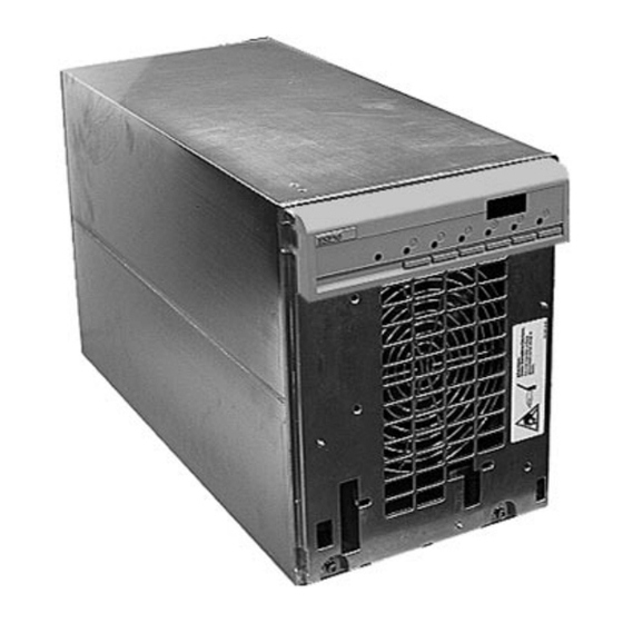
Page 8: Ese50 Solid State Disk
Introduction 1.1 General Information Figure 1–1 ESE50 Solid State Disk 1–2 Introduction... -
Page 9: Media Type, Model Byte, And Capacity
Introduction 1.1 General Information 1.1.1 Media Type, Model Byte, and Capacity The ESE50 has a unique media type and model byte depending on the capacity. This is done for operating system compatibility. Option Media Type Model Byte Capacity (LBNs) ESE50–AA,AB ESE52 238080 ESE50–BA,BB... -
Page 10: Hardware Maintainability
Introduction 1.1 General Information Figure 1–2 Typical ESE50 SSD Subsystem Configuration DRIVE CABINET DRIVE CABINET ESE50 CONTROLLER A ESE50 SDI CONTROLLER A I/O BULKHEAD I/O BULKHEAD SDI CABLES 1.2 Hardware Maintainability The ESE50 SSD uses modular field replaceable units (FRUs) for easy access and servicing. -
Page 11: Drive-Resident Diagnostics Overview
Introduction 1.3 Dual-Port Capability Figure 1–3 ESE50 Dual-Port Configuration DRIVE CABINET ESE50 PORT CONTROLLER A CONTROLLER B SDI CONTROLLER A SDI CONTROLLER B I/O BULKHEAD I/O BULKHEAD SDI CABLES 1.4 Drive-Resident Diagnostics Overview Drive-resident diagnostics run during powerup and spin-up cycles to test basic drive functions. -
Page 12: Orderly Shutdown
Introduction 1.5 User Precautions/Recommendations ESE50–AA/AB (120 MB), ESE50–BA/BB (600 MB), and ESE50–DA/DB (1 GB) options options contain the complete data retention system. Table 1–2 lists the data retention times. Table 1–2 Summary of Data Retention Times Maximum Number of Data Complete Backups Retention Backup... -
Page 13: Recommended Operating Temperature
Introduction 1.5 User Precautions/Recommendations Caution The ESE50 data retention system should never be considered a substitute for a site-specific data backup policy. The ESE50 should be treated as any other master media in this regard. 1.5.3 Recommended Operating Temperature The ESE50 SSD is designed to operate in a Class A environment. 1.5.4 Electrostatic Discharge Protection Electrostatic discharge (ESD) is caused by the buildup and release of static electricity. -
Page 14: Esd Wrist Strap
Introduction 1.5 User Precautions/Recommendations Figure 1–4 ESD Wrist Strap 1–8 Introduction... -
Page 15: Ese50 Ssd Maintenance Strategy
Introduction 1.6 ESE50 SSD Maintenance Strategy 1.6 ESE50 SSD Maintenance Strategy It is recommended that only trained Digital Customer Services engineers attempt to service an ESE50 SSD. To repair an ESE50, replace the FRU. An extensive set of drive-resident microcode diagnostics and a drive-resident error log help simplify problem isolation. -
Page 16: Additional Electrical Specifications By Model For The Ese50 Ssd
Introduction 1.7 ESE50 SSD Specifications Table 1–3 (Cont.) Specifications for the ESE50 SSD Power Requirements Standards UL listed; CSA certified; FCC Class A verified Voltage 120/208 Vac at 60 Hz; Single-phase WYE 220/240 Vac at 50 Hz Inrush Current: 5.08 amperes peak @ 132 Vac 2.31 amperes peak @ 264 Vac Running current: 1.87 amps @ 120 Vac... -
Page 17: Installation
Installation 2.1 Introduction This chapter describes site preparation and planning considerations and procedures for unpacking the ESE50. Cabling, safety precautions, and voltage selection are also discussed. 2.2 Site Preparation and Planning Site preparation and planning are necessary before installing an ESE50 or subsystem. -
Page 18: Unpacking Ese50 Add-Ons
Installation 2.3 Unpacking ESE50 Add-Ons 2.3 Unpacking ESE50 Add-Ons Check packaging for external damage. Read and save any packing information. Unpack the ESE50 SSD using the following procedure (Figure 2–1): 1. Cut and remove the shipping straps. 2. Open the shipping container. 3. -
Page 19: Ese50 Disk Drive Packaging
Installation 2.3 Unpacking ESE50 Add-Ons Figure 2–1 ESE50 Disk Drive Packaging Installation 2–3... -
Page 20: Installing Sdi Cables And Power Cords
Installation 2.4 Installing SDI Cables and Power Cords 2.4 Installing SDI Cables and Power Cords Use this section as a reference only. For detailed procedures and illustrations, refer to subsystem-specific documentation. Most fully configured cabinets have internal SDI cables and power cords in place. However, when installing an ESE50 unit in an SA900 cabinet, the CK-SA900-L2 installation kit is required. -
Page 21: Power And Safety Precautions
Installation 2.5 Power and Safety Precautions 2.5 Power and Safety Precautions The ESE50 does not present any unusual fire or safety hazards. However, it is recommended that you check ac power wiring for the computer system to determine adequate capacity for expansion. To protect personnel and equipment, ensure that power sources meet the specifications required for this equipment. -
Page 22: Power Controller (Example)
Installation 2.5 Power and Safety Precautions Figure 2–2 881 Power Controller (Example) POWER CONTROLLER BUS/OFF/ON SWITCH (CLOCKWISE FROM TOP) FUSE POWER CORD LABEL POWER CONTROL STRAIN RELIEF BUS CONNECTORS CIRCUIT BREAKER POWER GROMMETED FUSE CORD CORD UNDELAYED OPENING DELAYED (0.5 SEC) SERIAL/LOGO LABEL CXO-2136A... -
Page 23: Ac Power Wiring
The 40-inch cabinet requires single-phase power. Check system-specific documentation for the power requirements for your system. The wiring used by Digital Equipment Corporation conforms to UL, CSA, and ISE standards. Figure 2–3 shows the ac plug configurations for the ESE50s and the 881 and 874 power controllers. -
Page 24: Electrical Plug Configurations
Installation 2.6 AC Power Wiring Figure 2–3 Electrical Plug Configurations POWER CORDS GOING TO POWER CONTROLLER 120V 60HZ POWER CORD DEC NO. A-PS-1700083-23 PLUG - POWER CONTROLLER END 240V 50HZ POWER CORD DEC NO. A-PS-1700083-24 PLUG - POWER CONTROLLER END 120/240V 47-63HZ 10A/6A POWER CORD... -
Page 25: Operating Instructions
Operating Instructions 3.1 Introduction This chapter describes the operator control panel (OCP), drive-resident powerup diagnostics, acceptance tests, and ESE50 operating modes. Functional flowcharts are included to aid the user when operating the ESE50. 3.2 OCP Functions, Switches, and Indicators The OCP interfaces with the ESE50 SSD and performs the following functions: •... -
Page 26: Powerup Diagnostics
Operating Instructions 3.2 OCP Functions, Switches, and Indicators Figure 3–1 ESE50 OCP Four−Character Alphanumeric Display Unit Number ESE50 WRITE READY FAULT PROTECT TEST FAULT WRITE PORT A PORT B TEST Switch Switch Switch Switch Switch PROTECT Status Switch ESE50_OCP Indicator 3.3 Powerup Diagnostics Do not select any OCP switches. -
Page 27: Testing Spin-Up Drive
Operating Instructions 3.3 Powerup Diagnostics 3.3.3 Testing Spin-Up Drive To spin up the drive: 1. Deselect the Test switch. The Test LED indicator goes out and the unit address (if programmed) is displayed. 2. Select the Run switch. (An R appears in the OCP display, and the Run LED indicator lights.) Allow the drive to reach the ready state, as indicated by the front panel Ready LED indicator. -
Page 28: Programming The Drive Unit Address
Operating Instructions 3.4 Programming the Drive Unit Address 3.4 Programming the Drive Unit Address Once power has been applied to the drive, set the unit address. You must set the drive unit address before placing the ESE50. The ESE50 unit address is programmable from 0 to 4094. (Remember that the operating system or subsystem type can limit the unit address range.) Use the following procedure to set the drive unit address. -
Page 29: Unit Address Programming Flowchart
Operating Instructions 3.4 Programming the Drive Unit Address Figure 3–2 Unit Address Programming Flowchart NORMAL MODE INCREMENT DISPLAY = NUMBERS 0−9 BY SELECTING PORT B SWITCH DESELECT PORT A AND B TO SET UNIT SELECT ADDRESS PORT A SWITCH DISPLAY = DISPLAY = SELECT TEST SWITCH (TEST... -
Page 30: Ese50 Operating Modes
Operating Instructions 3.5 ESE50 Operating Modes 3.5 ESE50 Operating Modes The ESE50 operates in three setup modes: normal, fault display, and test. The following sections describe the functions of each mode. 3.5.1 Normal Mode Setup The normal mode setup is the usual operating mode of the ESE50 SSD. Switch selection during normal operation usually consists of the Run switch, Write Protect switch (for normal write protection), and Port A or B switches. -
Page 31: Fault Display Example
Operating Instructions 3.5 ESE50 Operating Modes Figure 3–3 Fault Display Example NORMAL MODE DISPLAY = FAULT SELECT INDICATION FAULT ON DRIVE SWITCH OCP LAMP TEST SELECT (2 SEC) FAULT SWITCH DISPLAY = SELECT FAULT SWITCH FAULT CLEARS NORMAL MODE NOTE: Any combination of legal alphanumeric error codes (HEX). -
Page 32: Test Mode Setup
Operating Instructions 3.5 ESE50 Operating Modes 3.5.3 Test Mode Setup You must enter the test mode to set the ESE50 unit address or to run resident diagnostic tests. In this mode, Port A and Port B switches have the function of selecting both the unit address numbers and test numbers. -
Page 33: Diagnostics
Diagnostics 4.1 General Information This chapter contains general information concerning drive-resident diagnostics and acceptance testing procedures. 4.2 Drive-Resident Diagnostics Drive-resident diagnostics are invoked under four conditions: • Powerup or master processor reset • External init (SDI command) • Operator control panel (OCP) test mode selection •... -
Page 34: Powerup Resident Diagnostics
Diagnostics 4.2 Drive-Resident Diagnostics 4.2.1 Powerup Resident Diagnostics The drive-resident diagnostics that run at powerup or master processor reset run without manual intervention in the following order: • Master CPU test • Master ROM test • Master RAM test • Master timer test •... -
Page 35: Test Selection Flowchart
Diagnostics 4.3 Test Selection from the OCP Figure 4–1 Test Selection Flowchart NORMAL MODE SELECT PORT DISPLAY = A SWITCH (MSD BEGINS FLASHING) SELECT PORT SWITCHES TO DESELECT DISPLAY = PORT(S) INCREMENT DISPLAY = NUMBERS 0−9 BY SELECTING PORT B SELECT TEST SWITCH SWITCH (TEST... -
Page 37: A Customer Equipment Maintenance
Customer Equipment Maintenance This appendix will assist customers in maintaining their equipment to ensure the highest level of equipment performance and reliability. Specifically, this appendix addresses the maintenance of SA6xx/SA8xx storage array cabinet systems. A.1 Customer Responsibilities The customer is directly responsible for: •... -
Page 38: Customer Responsibilities
Customer Equipment Maintenance A.1 Customer Responsibilities A.1.2 Ongoing Equipment Care Routine care of the equipment should be done on a regular basis: • Keep the immediate area in front of the storage array cabinets free of obstructions. • Keep the exterior of the cabinets and the surrounding area clean. Use a lint-free cloth and isopropyl alcohol to remove sticky residue left on painted surfaces by customer cabinet number labels, and so forth. -
Page 39: Customer Equipment Maintenance Log
Customer Equipment Maintenance A.1 Customer Responsibilities Figure A–1 Customer Equipment Maintenance Log CUSTOMER EQUIPMENT MAINTENANCE LOG FOR STORAGE ARRAY CABINETS DATE OF SERVICE TYPE OF SERVICE PERFORMED CABINET S/N CABINET S/N CABINET S/N CABINET S/N CXO-2964A Customer Equipment Maintenance A–3... - Page 41 Index idle loop, 1–5 input current (amps), 1–10 inrush current, 1–9 AC power wiring, 2–7 maintenance strategy, 1–9 configurations ESE50 SSD subsystem, 1–3 controllers 881 power, 2–5 customer equipment maintenance, A–1 functions, 3–1 customer equipment maintenance log, A–3 lamp testing, 3–2 switches and indicators, 3–1 operating modes RA90/RA92, 3–6...
- Page 42 site preparation and planning operating recommendations, 1–7 environment, 2–1 test selection from the OCP, 4–2 floor loading, 2–1 testing operating temperature and humidity, 2–1 spin-up drive, 3–3 power requirements, 2–1 thermal stabilization, 2–1 specifications ESE50 SSD, 1–9 start/stop time, 1–9 unit address programming from the OCP, 3–4 unpacking add-on disk drives, 2–2...
Need help?
Do you have a question about the ESE50 SDI and is the answer not in the manual?
Questions and answers