Table of Contents
Advertisement
Operation, Parts
Brushless Cordless
HandHeld Airless Sprayers
Important Safety Instructions
Read all warnings and instructions in this manual, on the unit, and in the battery and
charger manual. Be familiar with the controls and the proper usage of the equipment.
Save these instructions.
ti30553a
844-241-9499
For portable spray applications of architectural paints and coatings only.
Not approved for use in explosive atmospheres or hazardous locations.
For professional use only.
3A4803A
Operational video.
http://graco.com/hhsupport
EN
Advertisement
Table of Contents

Related Manuals for Graco 3A4803A


Summary of Contents for Graco 3A4803A
-
Page 1: Important Safety Instructions
Operation, Parts Brushless Cordless 3A4803A HandHeld Airless Sprayers Important Safety Instructions Read all warnings and instructions in this manual, on the unit, and in the battery and charger manual. Be familiar with the controls and the proper usage of the equipment. -
Page 2: Table Of Contents
Graco Limited Warranty ........ -
Page 3: Models - Cordless Airless Handhelds
FFLPxxx 17P931 Ultra MAX 17N224 100V 17M370 230V 17P257 Ultimate MX 17N225 Ultra MAX 230V * – Tool only, without battery and charger. Operating pressure range: 500 – 2000 psi (35 – 138 bar, 3.5 MPa – 14 MPa) 3A4803A... -
Page 4: Important User Information
Before using your sprayer read this Owners Manual for complete instructions on proper use and safety warnings. Congratulations! You have purchased a high-quality paint sprayer made by Graco Inc. This sprayer is designed to provide superior spray performance with all architectural paints and coatings. -
Page 5: General Power Tool Safety Information
Loose clothes, jewelry or long hair can be caught in moving parts. • If devices are provided for the connection of dust extraction and collection facilities, ensure these are connected and properly used. Use of dust collection can reduce dust-related hazards. 3A4803A... - Page 6 Service • Have your power tool serviced by a qualified repair person using only identical replacement parts. This will ensure that the safety of the power tool is maintained. 3A4803A...
-
Page 7: Warnings
Unwind the ground wire from the spool and plug it into a properly grounded electrical outlet. If the ground wire is not long enough to reach a grounded electrical outlet, a 3-wire grounded extension cord may be used to reach a grounded outlet. ti30554a 3A4803A... -
Page 8: Fire And Explosion Hazard
Check parts for signs of damage. Replace any damaged parts. • This system is capable of producing 2000 psi (138 bar, 14 MPa). Use Graco replacement parts or accessories that are rated a minimum of 2000 psi (138 bar, 14 MPa). - Page 9 • Do not operate the unit when fatigued or under the influence of drugs or alcohol. • Always replace cracked, broken or missing parts immediately with genuine Graco parts. See Replacement Parts, page 32. • Do not alter or modify equipment. Alterations or modifications may void agency approvals and create safety hazards.
-
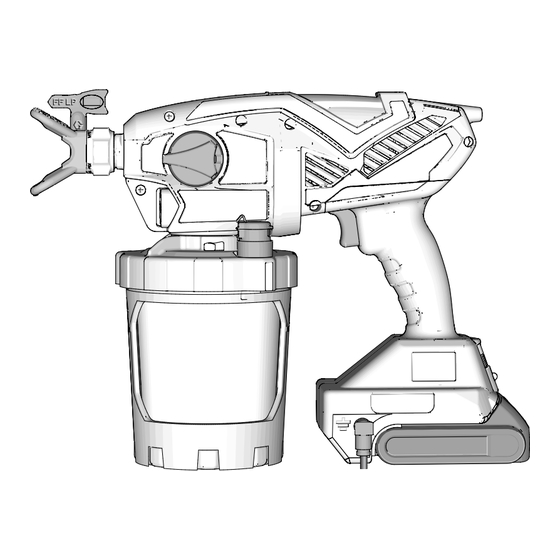
Page 10: Know Your Sprayer
SPRAY PUMP Prime Pump/Spray Knob Cup Cover Battery FlexLiner Sprayer Trigger Cup Support Speed Control, ProControl II VacuValve Cap Spray Tip. Reverse-A-Clean (RAC) VacuValve Air Hole Spray Tip Guard VacuValve Reservoir Diagnostic Light Pump Filter Ground Plug and Spool 3A4803A... -
Page 11: Start Up
Remove battery from the sprayer. Turn Prime Pump/Spray Knob down to PRIME PUMP position to relieve pressure. Replace and charge battery only in a well-ventilated area and away from flammable or combustible materials, including paints and solvents. ti29755a 3A4803A... -
Page 12: Starting A New Job
Align VacuValve on cup cover with Prime Pump/Spray knob. Push cup assembly onto sprayer and twist to lock. ti26894a ti30556a 3A4803A... - Page 13 12. You are now ready to spray. NOTE: For best results; to evacuate all material from the FlexLiner when the material is nearly gone, gently squeeze the bottom of the FlexLiner to push the last of the material up to the cup lid. ti29723a 3A4803A...
-
Page 14: Refilling Flexliner
Follow steps 2 – 12 in Starting a New Job, page 12. • If sprayer still does not spray, see Sprayer Diagnostics, page 35. If material sprays while upside down there is air in the cup. Repeat steps above. 3A4803A... -
Page 15: How To Spray
Hold sprayer 12 in. (30 cm) from surface you are moving too fast. If material drips, you and aim straight at surface. Tilting the are moving too slow. See Troubleshooting, sprayer to direct the spray angle causes page 35. an uneven finish. 3A4803A... -
Page 16: Triggering Sprayer
Aim sprayer at bottom edge of previous THICK stroke, overlapping each stroke by half. UNEVEN FINISH THIN ti29743a EVEN FINISH ti29745a Rotating the spray tip guard changes the pattern to either the vertical or horizontal orientations. THIN THICK THIN 3A4803A... -
Page 17: Spray Pattern Quality
If tails persist when spraying at the highest spray pressure: • Spray tip may be worn. See Tip and Pressure Selection, page 15. • A smaller spray tip may be needed. • Material may need to be thinned. Follow manufacturers recommendations. ti29773a 3A4803A... - Page 18 SPRAY position. Turn Prime Pump/Spray knob forward to SPRAY position, and resume spraying. If spray tip is still clogged, you may have to repeat steps 1 – 5, or replace with new spray tip assembly. See Spray Tip Installation, page 24. ti29774a 3A4803A...
-
Page 19: Cleanup
Do not store solvents other than mineral spirits in sprayer. Always flush with Graco Pump Armor prior to storage. Cleaning Sprayer To avoid serious injury or damage to equipment: •... - Page 20 To clean the sprayer, fill FlexLiner approximately half-full with appropriate cleaning fluid (warm water or mineral spirits). ti30558a Securely tighten cup support with FlexLiner to cup cover/sprayer. 3A4803A...
- Page 21 If more flushing is needed, ti30231a remove the tip from the sprayer to avoid With the spray tip in the SPRAY excessive wear. position, pull the trigger for five seconds. Release the trigger. 3A4803A...
-
Page 22: Cleaning Sprayer Exterior
Cleaning Sprayer Exterior Wipe paint off the outside of the sprayer using a soft cloth moistened with water or flushing fluid. Do NOT submerge the sprayer. ti23406a 3A4803A... -
Page 23: Storage
2 oz. (60 ml) PUMP and pour any remaining Pump Armour ARMOR into pump opening. back into Pump Armor bottle. Replace child-resistant cap and tighten securely for storage. 10. Store sprayer indoors in a cool, dry place. Store in an upright position only. 3A4803A... -
Page 24: Common Procedures
(water, mineral spirits, or compatible oil-based solvent) ti24653a immediately after use to ensure material is not allowed to dry in spray tip. Failure to do so will result in damage to the spray tip. See Cleanup, page 19. 3A4803A... -
Page 25: Flush A New Sprayer
28 for additional information when using oil-based or flammable materials. Remove cup assembly from the sprayer by turning and pulling down. ti23361a Fill FlexLiner with cleaning fluid. See Cleaning Fluid Compatibility, page 28. ti29775a Unscrew cup cover from the cup support. ti23383a ti23676a 3A4803A... - Page 26 Make certain the Prime Pump/Spray excessive wear. knob is in the Prime Pump position (pointed down). Set speed control to 10. 12. Sprayer is now flushed and ready for use. See Start Up, page 11. 3A4803A...
-
Page 27: Reference
First digit when doubled = approximate fan width. Last two digits = tip hole size in thousands of an inch. For an 8 to 10 in. (203 to 254 mm) fan width and 0.010 (0.25 mm) hole size, order Part No. …410. 3A4803A... -
Page 28: Cleaning Fluid Compatibility
When flushing with solvents always follow Static Ground- ing Instructions (Oil-Based or flam- mable materials), page 28. • To avoid fluid splashing back on your skin or into your eyes, always aim gun at inside wall of pail. 3A4803A... -
Page 29: Maintenance
If outlet valve assembly was removed from the valve plug, assemble as shown. Leave a space between the end of the plug or front valve and shoulder on the outlet valve assembly. ti30369a 3A4803A... -
Page 30: Grounding Wire Repair
Loosen screw and remove broken wire. Insert stripped grounding wire and Loosen screw on terminal and remove tighten screw. broken wire. Strip insulation from grounding wire, insert into terminal and Replace rubber boot onto grounding tighten screw. plug. ti30561a 3A4803A... - Page 31 Notes Notes 3A4803A...
-
Page 32: Replacement Parts
Replacement Parts Replacement Parts ti30563a Ref. Torque Ref. Torque 10 in-lb (1.1 N•m) 55-65 in-lb (6.2 - 7.3 N•m) 8-10 in-lb (0.9 - 1.1 N•m) 5-7 in-lb (0.6 - 0.8 N•m) 10-15 in-lb (1.1 - 1.7 N•m) 3A4803A... -
Page 33: Parts List
Spray tip, Model; 17N223 17P236 Kit, enclosure, cover includes 7 of 37 Motor, part of Smartcontrol and enclosure (Ref. No. 12) Kit, tip seat and seal (5-pack) 17P501 Standard 17P502 Solvent 17R614 Screw, cross-head 128726 Screw, cross-head Continued on next page. 3A4803A... - Page 34 English, Spanish, French 17F690 Dutch, German, Italian 16H256 Reel, grounding Replacement available at no cost. * Battery and charger are dependent upon in country requirements. Replacement Danger and Warning labels, tags, and cards are available at no cost. 3A4803A...
-
Page 35: Troubleshooting
Diagnostic light blinks four times Replace pump and/or motor when trigger is pulled. Indicates assembly. locked rotor condition. Diagnostic light does not blink when Install battery or replace battery. trigger is pulled. Indicates battery is Replace Smartcontrol. not installed or is damaged. 3A4803A... - Page 36 See Refilling FlexLiner, page 14. Pump has reached the end of its life. Replace pump assembly. Diagnostic light blinks four times Replace pump and/or motor when the trigger is pulled. Indicates a assembly. locked rotor condition. 3A4803A...
- Page 37 FlexLiner. Make certain there is no damage to the FlexLiner lip or the cup cover gasket. Make certain that the FlexLiner lip and cup cover gasket is free of debris and dried paint. Replace FlexLiner. 3A4803A...
- Page 38 10 in. (25 cm) Incorrect spray tip for Install different size spray tip. application of material. See Spray Tip Installation, page 24. Spray tip is worn or Replace spray tip. See Spray damaged. Tip Installation, page 24. 3A4803A...
- Page 39 See Spray Tip Installation, completely into spray tip page 24. guard. ti30016a Material leaks around spray tip Spray tip seal and seat are See Spray Tip Installation, damaged or not properly page 24. guard or spray tip handle installed. 3A4803A...
-
Page 40: Technical Specifications
Changes in paint viscosity at very low or very high temperatures can affect sprayer performance. † per EN60745-1/EN50580 measured at 3.3 feet (1m) * Maximum initial battery voltage (measured without a workload) is 20 volts. Nominal voltage is 18. 3A4803A... -
Page 41: Graco Limited Warranty
Graco’s written recommendations. This warranty does not cover, and Graco shall not be liable for general wear and tear, or any malfunction, damage or wear caused by faulty installation, misapplication, abrasion, corrosion, inadequate or improper maintenance, negligence, accident, tampering, or substitution of non-Graco component parts. -
Page 42: Graco Information
Graco Limited Warranty Graco Information For the latest information about Graco products, visit www.graco.com. For patent information, see www.graco.com/patents. TO PLACE AN ORDER, contact your Graco distributor or call 1-888-541-9788 to identify the nearest distributor. 3A4803A... - Page 43 Notes Notes 3A4803A...
- Page 44 Original instructions. This manual contains English. MM 3A4803 Graco Headquarters: Minneapolis International Offices: Belgium, China, Japan, Korea GRACO INC. AND SUBSIDIARIES • P.O. BOX 1441 • MINNEAPOLIS MN 55440-1441 • USA Copyright 2017, Graco Inc. All Graco manufacturing locations are registered to ISO 9001. www.graco.com...
Need help?
Do you have a question about the 3A4803A and is the answer not in the manual?
Questions and answers
My Greco 3A4803A paint sprayer won’t spray. It has been thoroughly cleaned and stored for months. Can you help?