Keithley 2110 Reference Manual
5 1/2 digit multimeter
Hide thumbs
Also See for 2110:
- Calibration manual (35 pages) ,
- Quick reference (2 pages) ,
- Calibration manual (35 pages)

Related Manuals for Keithley 2110


Summary of Contents for Keithley 2110
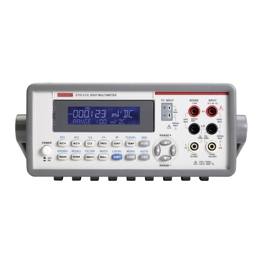
- Page 1 Model 2110 5½ Digit Multimeter Reference Manual 2110-901-01 Rev. C / August 2013 *P211090101C* 2110-901-01 A G r ea ter M e a su r e of C o nf i d e nce A Tektronix Company...
- Page 2 All rights reserved. Any unauthorized reproduction, photocopy, or use of the information herein, in whole or in part, without the prior written approval of Keithley Instruments, Inc. is strictly prohibited. All Keithley Instruments product names are trademarks or registered trademarks of Keithley Instruments, Inc.
-
Page 4: Safety Precautions
Keithley Instruments products are designed for use with electrical signals that are measurement, control, and data I/O connections, with low transient overvoltages, and must not be directly connected to mains voltage or to voltage sources with high transient overvoltages. - Page 5 (note that selected parts should be purchased only through Keithley Instruments to maintain accuracy and functionality of the product). If you are unsure about the applicability of a replacement component, call a Keithley Instruments office for information.
-
Page 6: Table Of Contents
Table of Contents Introduction ....................... 1-1 Welcome ..........................1-1 Contact information ......................1-1 CD-ROM contents ........................ 1-2 Organization of manual sections ..................1-2 Capabilities and features...................... 1-3 Measurement ranges and functions ..................1-4 Mathematical operations ......................1-4 Startup software and PC utilities ....................1-4 Standard accessories ........................ - Page 7 Table of Contents Model 2110 5½ Digit Multimeter Reference Manual Ratio measurements ......................... 3-4 Current measurements ......................3-6 Resistance measurements ......................3-9 Frequency and period measurements ..................3-12 Continuity measurements......................3-15 Diode measurements ......................3-15 Temperature measurement ..................... 3-17 Capacitance measurements....................3-24 Secondary measurement function ...................
- Page 8 Model 2110 5½ Digit Multimeter Reference Manual Table of Contents Query commands ........................5-10 Program messages ......................... 5-10 Output Data ..........................5-12 SCPI signal-oriented measurement commands ..............5-13 :CONFigure:<function> [<range>|MIN|MAX|DEF,<resolution>|MIN|MAX|DEF] ...... 5-14 :FETCh[1|2]? ........................... 5-16 :INITiate........................... 5-16 :READ[1|2]? ..........................5-17 :MEASure[:<function>]? <range>|MIN|MAX|DEF,<resolution>|MIN|MAX|DEF .......
- Page 9 Table of Contents Model 2110 5½ Digit Multimeter Reference Manual [SENSe:]FUNCtion [1|2] "<function>"..................5-45 [SENSe:]PERiod:APERture <n>|MIN|MAX ................5-46 [SENSe:]PERiod:VOLTage:RANGe <n>|MIN|MAX ..............5-46 [SENSe:]PERiod:VOLTage:RANGe:AUTO <b>..............5-47 [SENSe:]RESistance:RANGe <n>|MIN|MAX ................5-47 [SENSe:]RESistance:RANGe:AUTO <b> ................5-47 [SENSe:]RESistance:RESolution <n>|MIN|MAX ..............5-48 [SENSe:]RESistance:NPLCycles <n>|MIN|MAX ..............5-49 [SENSe:]TCOuple:RJUNction:REAL? ..................
- Page 10 Model 2110 5½ Digit Multimeter Reference Manual Table of Contents Next steps ......................... 7-1 Additional Model 2110 information ..................7-1 Maintenance ......................A-1 Line fuse replacement ......................A-1 Current input fuse replacement .................... A-3 Upgrading the firmware ......................A-4 Status model ......................B-1 Overview ..........................
-
Page 12: Introduction
General information ..............1-5 Welcome Thank you for using a Keithley Instruments product. The Model 2110 Digit Multimeter (DMM) features 12 measurement functions and 7 math functions, and has dual-line display capability, which allows it to display two different measurements concurrently. -
Page 13: Cd-Rom Contents
(including troubleshooting and optimization) should refer to the Reference Manual. • Calibration Manual: Includes procedures to verify that the Model 2110 accuracy is within the limits stated in the instrument’s one-year accuracy specifications. • Drivers and release notes: IVI Instrument Driver, driver for National Instruments LabVIEW™, and related release notes. -
Page 14: Capabilities And Features
The Model 2110 has 0.0012% one-year basic DC voltage accuracy and 0.020% one-year basic resistance accuracy up to the 1 MΩ range. At 5½ digits, the Model 2110 delivers over 200 readings per second via the USB remote interface. At the fast 4½ digit setting, readings can be stored internally at a rate of 50,000 per second. -
Page 15: Measurement Ranges And Functions
Programmable A-D converter and filter settings for signal-to-noise optimization Mathematical operations The Model 2110 allows you to perform the following seven mathematical operations on measurement readings: Percentage, Average (Min/Max, Count), NULL, Limits, mX+b, dB, and dBm. Startup software and PC utilities The following start-up software and PC utilities are included: •... -
Page 16: Optional Accessories
Displaying the instrument's serial number To display the serial number on the front panel: 1. If the Model 2110 is in remote operation, press the SHIFT (LOCAL) key once to place the instrument in local operation. 2. Press the SHIFT key. -
Page 17: Power-On Settings
Figure 2: Dimensions Power-on settings See the following table for information about the Model 2110 factory default settings. These settings are also restored when the instrument is turned on and when the instrument receives a *RST command from a remote interface. -
Page 18: General Specifications
Model 2110 5½ Digit Multimeter Reference Manual Section 1: Introduction Function Default Diode test Digits Range 1 mA Rate 0.2 PLC Resistance Digits 5.5 (1 PLC) Range 1 kΩ Temperature Digits 4.5 (1 PLC) Thermocouple K type Triggers Source Immediate... -
Page 20: General Overview
Follow the procedure below to connect the Model 2110 to line power and to turn on the instrument. The Model 2110 operates from a line voltage of 100 V to 240 V at a frequency of 50 Hz or 60 Hz. Line voltage is set on the rear panel. - Page 21 Section 2: General overview Model 2110 5½ Digit Multimeter Reference Manual The power cord supplied with the Model 2110 contains a separate protective earth (safety ground) wire for use with grounded outlets. When proper connections are made, the instrument chassis is connected to power-line ground through the ground wire in the power cord.
- Page 22 Model 2110 5½ Digit Multimeter Reference Manual Section 2: General overview 2. Press the latch to unlatch the voltage setting selector container, as shown in the following figure (a flat blade screwdriver may be required). Figure 4: Unlatching voltage selector 3.
-
Page 23: Fuse Replacement
Section 2: General overview Model 2110 5½ Digit Multimeter Reference Manual 4. Open the clips on the sides and remove the voltage setting selector from the container, as shown in the following figure. Figure 6: Open clips 5. Turn the voltage setting to the correct setting. -
Page 24: Front Panel Overview
Section 2: General overview Power-up sequence Self-test procedures are built into the Model 2110 for checking that the logic and measurement hardware are functioning properly. Every time the instrument power is turned on, a set of test procedures is performed to make sure the basic functions of the instrument work properly. If any error occurs during self-test procedures, it indicates that parts of the instrument are not operating properly and need to be serviced. -
Page 25: Display
Section 2: General overview Model 2110 5½ Digit Multimeter Reference Manual (1) Display The instrument display has a primary and a secondary display area. There are additional indicators at the upper side (top) and right side of the display to show the state or the condition of an ongoing measurement. -
Page 26: The Power Key
Model 2110 5½ Digit Multimeter Reference Manual Section 2: General overview The following table describes the meaning of each lit indicator. Indicator Indicates Instrument is controlled via the GPIB Interface. Remote interface operation via the USB Interface. Manual range mode is selected. - Page 27 Section 2: General overview Model 2110 5½ Digit Multimeter Reference Manual Shifted keys To perform a shifted function or operation, press SHIFT and then press the key with the label for the function you want to perform printed above it. The procedures in this manual that require you to use a shifted key sequence list the key name followed by the shifted key name in parentheses.
- Page 28 Model 2110 5½ Digit Multimeter Reference Manual Section 2: General overview The following table describes the functions and shifted functions associated with each key. The shifted functions are shown with a shaded background. Function Selects DC voltage measurement. Selects AC voltage measurement.
-
Page 29: Range And Scroll Keys
Section 2: General overview Model 2110 5½ Digit Multimeter Reference Manual (4) RANGE and scroll keys Keys Description ◄ and ► Use ► and ◄ keys to scroll through options. ▲ and ▼ Use ▲ and ▼ keys to change the range while measuring. -
Page 30: Main Menu
Model 2110 5½ Digit Multimeter Reference Manual Section 2: General overview Menu navigation Selecting menus To select menus and submenus, use the keys as follows: • To navigate to the Main menu, press SHIFT, and then press CONFIG (MENU). •... - Page 31 Section 2: General overview Model 2110 5½ Digit Multimeter Reference Manual Keys, menus, and selection Description Press the ACV key. CONFIG Press the CONFIG key to display configuration options. Use ► and ◄ keys to select bandwidth. Refer to BAND WIDTH...
- Page 32 Model 2110 5½ Digit Multimeter Reference Manual Section 2: General overview Keys, menus, and selection Description SHIFT Press the SHIFT key to access the shifted function for the next key you press. DCV (DCI) Press the DCV (DCI) key. CONFIG Press the CONFIG key to configure DC current measurements.
- Page 33 Section 2: General overview Model 2110 5½ Digit Multimeter Reference Manual Keys, menus, and selection Description ENTER (2ND) Press ENTER (2ND) key. CONFIG Refer to Secondary measurement function (on page 3-26) for details. Select OFF to turn off the dual measurement function off.
- Page 34 Model 2110 5½ Digit Multimeter Reference Manual Section 2: General overview Keys, menus, and selection Description Use ► and ◄ keys to display additional selections. Refer to RANGE Range selection (on page 3-39) for details. Select CAP to configure capacitance as the second function.
- Page 35 Section 2: General overview Model 2110 5½ Digit Multimeter Reference Manual Keys, menus, and selection Description Press ► and ◄ keys to display additional selections. Refer to NULL (MATH) Math operations (on page 3-48) for details. Turn the math function off.
- Page 36 (on page 6-2) for details. Access remote command language settings. Refer to Selecting the LANGUAGE language (on page 2-23) for details. DEFAULT Set default language. The default language is: Model 2110 SCPI. COMPATIBLE Set to SCPI-compliant DMM language mode. 2110-901-01 Rev. C/August 2013 2-17...
-
Page 37: Rear Panel Overview
GPIB ADDRESS Enter or change GPIB address. Rear panel overview The rear panel of the Model 2110 is shown in the following figure. This figure includes important abbreviated information that should be reviewed before using the instrument. Figure 13: Rear panel (1) Voltmeter complete output terminal (VM COMP) The VM COMP output terminal outputs a low-true pulse after each completed measurement. -
Page 38: Protective Earth (Safety Ground)
(on page C-1) for information about using this connector. Figure 14: USB connector GPIB connector To connect Model 2110 to the GPIB bus, use a cable equipped with standard IEEE-488 connectors, as shown below. Refer to GPIB setup (on page C-7) for information about using this connector. -
Page 39: System Operations
Section 2: General overview Model 2110 5½ Digit Multimeter Reference Manual Figure 15: GPIB connector Set the GPIB address The GPIB address value is set to 16 at the factory. The address can be set to any address value between 0 and 30. However, the address must be unique in the system. It cannot conflict with the address assigned to another instrument or to the GPIB controller. -
Page 40: Turning Off Measurement Display
Model 2110 5½ Digit Multimeter Reference Manual Section 2: General overview Turning off measurement display You have the option to stop measurements from showing on the display. When the measurement display is turned off, the OFF indicator is lit. This indicator does not mean the display is turned off, but only that the acquired readings will not be sent to the display. -
Page 41: Turning The Beeper Off Or On
Model 2110 5½ Digit Multimeter Reference Manual Turning the beeper off or on The Model 2110 beeps when certain conditions are met or when an error occurs. You can only turn off the beeper for some operations. The beeper sound remains in other operations, such as front-panel key-presses. -
Page 42: Selecting The Initial Operating Mode
Model 2110 5½ Digit Multimeter Reference Manual Section 2: General overview Selecting the initial operating mode The Model 2110 provides the option to save the current operating settings or restore the factory default settings when the instrument is turned on. Refer to Power-on settings (on page 1-6) for information about default settings. -
Page 43: Viewing Errors In The Error Queue
NO ERRORS - Indicates that there are no error messages in the queue. Viewing system version The Model 2110 system version is a number that indicates the version of firmware installed on each of the instrument's processors. To view the system version, use the following procedure: 1. -
Page 44: Basic Dmm Operation
Basic measurement functions ..........3-1 Triggering and data buffer ............3-28 Enhancing measurement performance ........3-37 Basic measurement functions The Model 2110 5½ Digit Multimeter can perform the following measurements: • Voltage (DC and AC) • Ratio (DC voltage input / DC voltage reference) •... - Page 45 Model 2110 5½ Digit Multimeter Reference Manual To eliminate thermal EMFs caused by the differences between two metals, use copper test leads to connect your source signal to the Model 2110. Use the following procedure and commands to perform basic measurements. Refer to...
- Page 46 Model 2110 5½ Digit Multimeter Reference Manual Section 3: Basic DMM operation Remote operation Commands that use the <n> parameter can use the MINimum and MAXimum name parameters. MIN selects the minimum value and MAX selects the maximum value. Use the following commands to select the function (DCV or ACV), set a measure range, set...
-
Page 47: Ratio Measurements
Section 3: Basic DMM operation Model 2110 5½ Digit Multimeter Reference Manual Ratio measurements This feature calculates the ratio of an input DC voltage to a reference DC voltage using the following equation: This function only applies to DC voltage measurement. - Page 48 Model 2110 5½ Digit Multimeter Reference Manual Section 3: Basic DMM operation Connections for ratio measurements Figure 17: Connections for ratio measurements The reference signal must be between -2.1 V and 2.1 V. Remote operation Commands that use the <n> parameter can use the MINimum and MAXimum name parameters. MIN selects the minimum value and MAX selects the maximum value.
-
Page 49: Current Measurements
Section 3: Basic DMM operation Model 2110 5½ Digit Multimeter Reference Manual A measurement configuration command can also be used for ratio calculations. Use the following command to select the ratio function, set the measure range, set measurement resolution, perform a calculation, and acquire the reading. - Page 50 Model 2110 5½ Digit Multimeter Reference Manual Section 3: Basic DMM operation Connections for DC and AC current measurements The maximum input on the 3 A input terminals is 3 A, 250 V. The maximum input on the 10 A input terminals is 10 A.
- Page 51 Section 3: Basic DMM operation Model 2110 5½ Digit Multimeter Reference Manual Measurement configuration commands can also be used to perform measurements. Use the following commands to select a function (DCI or ACI), set the measure range, set measurement resolution, perform a measurement, and acquire the reading.
-
Page 52: Resistance Measurements
Model 2110 5½ Digit Multimeter Reference Manual Section 3: Basic DMM operation Resistance measurements There are two measurement methods for resistance: • 2-wire ohms • 4-wire ohms As shown in the figure in Connections for resistance measurements (on page 3-10), one pair of test leads are used for 2-wire ohms measurement. - Page 53 Section 3: Basic DMM operation Model 2110 5½ Digit Multimeter Reference Manual Connections for resistance measurements Source current flows from INPUT HI to INPUT LO as shown in the following figure. Figure 19: Connections for resistance measurements 3-10 2110-901-01 Rev. C/August 2013...
- Page 54 Model 2110 5½ Digit Multimeter Reference Manual Section 3: Basic DMM operation Remote operation Commands that use the <n> parameter can use the MINimum and MAXimum name parameters. MIN selects the minimum value and MAX selects the maximum value. Use the following commands to select the function (W2 or W4), set a measure range, and perform a measurement: FUNCtion "RESistance"...
-
Page 55: Frequency And Period Measurements
For manual ranging, press the RANGE ▲ and ▼ keys to select a measurement range. 4. As shown below, connect the AC signal to the Model 2110 and observe the reading on the display. If the input signal exceeds the selected range, the overflow message OVLD is displayed. - Page 56 Model 2110 5½ Digit Multimeter Reference Manual Section 3: Basic DMM operation Connections for frequency and period measurements Figure 20: Connections for FREQ and PERIOD 2110-901-01 Rev. C/August 2013 3-13...
- Page 57 Section 3: Basic DMM operation Model 2110 5½ Digit Multimeter Reference Manual Remote operation Commands that use the <n> parameter can use the MINimum and MAXimum name parameters. MIN selects the minimum value and MAX selects the maximum value. Use the following commands to select the function (frequency or period), set a measure range, set...
-
Page 58: Continuity Measurements
The default threshold voltage band is between 0.3 V and 0.8 V, and the reading rate is 0.1 PLC. The threshold voltage band can be adjusted from 0.01 V up to 1.2 V. The Model 2110 beeps when the measured diode voltage is within the threshold band. - Page 59 Section 3: Basic DMM operation Model 2110 5½ Digit Multimeter Reference Manual Front-panel operation Perform the following steps to measure the threshold voltage of a diode: 1. Connect the diode to the instrument, as shown below. These connections forward-bias the diode.
-
Page 60: Temperature Measurement
Front-panel operation Perform the following steps to measure temperature using an RTD or thermistor: 1. Referring to the drawing below, connect the RTD (or thermistor) to the Model 2110. 2. Press the TEMP and CONFIG keys. 3. Select the sensor: a. - Page 61 Section 3: Basic DMM operation Model 2110 5½ Digit Multimeter Reference Manual Connections to measure temperature using an RTD The following figure shows how to connect RTD probes to the instrument. For the 3-wire probe, make sure to connect the SENSE LO terminal to the INPUT LO terminal. Source current flows from INPUT HI to INPUT LO as shown in the following figure.
- Page 62 The table below shows the default coefficient values for the PT100, D100, F100, PT385, and PT3916 RTD sensors. For the Model 2110, these values are fixed and cannot be changed. However, if you need to use different coefficient values for these sensors, you can use the USER sensor type. The USER sensor type allows you to enter your own values.
- Page 63 Section 3: Basic DMM operation Model 2110 5½ Digit Multimeter Reference Manual Entering sensor coefficients There are three RTD sensor types that allow you to enter coefficient values for sensor parameters. The coefficients are provided with the documentation supplied by the manufacturer of the RTD.
- Page 64 Model 2110 5½ Digit Multimeter Reference Manual Section 3: Basic DMM operation Use the following commands to enter the parameter coefficients for the USER sensor: TEMPerature:RTD:RZERo <n> = R-zero value <n> TEMPerature:RTD:ALPHa <n> = Alpha value <n> TEMPerature:RTD:BETA <n> = Beta value <n>...
-
Page 65: Thermocouple Measurements
Section 3: Basic DMM operation Model 2110 5½ Digit Multimeter Reference Manual Thermocouple measurements The following table lists the temperature range for the supported thermocouple (TC) types: Thermocouple temperature measurement ranges Thermocouple type Temperature range (°C) Temperature range (°F) 600 to 1820... - Page 66 Section 3: Basic DMM operation Front-panel operation Perform the following steps to configure the Model 2110 for thermocouple measurements: 1. Press the SHIFT key and then press TEMP (TCOUPL). 2. Select the sensor type (B, C, E, J, K, N, R, S, or T): a.
-
Page 67: Capacitance Measurements
100 µF, 1 mF, and 10 mF. Front-panel operation Perform the following steps to measure capacitance: 1. Connect the capacitance to the Model 2110, as shown below. 2. Press the SHIFT and FREQ ( ) keys. 3. Select a measurement range (auto or manual): •... - Page 68 Model 2110 5½ Digit Multimeter Reference Manual Section 3: Basic DMM operation Connections to measure capacitance Figure 24: Connections for capacitance Remote operation Commands that use the <n> parameter can use the MINimum and MAXimum name parameters. MIN selects the minimum value and MAX selects the maximum value.
-
Page 69: Secondary Measurement Function
Section 3: Basic DMM operation Model 2110 5½ Digit Multimeter Reference Manual Secondary measurement function The instrument provides dual measurement capability. When you enable the secondary measurement function, or second function (2ND), you make two measurements at the same time (series measurements). - Page 70 Model 2110 5½ Digit Multimeter Reference Manual Section 3: Basic DMM operation To simultaneously measure DCI and DCV from the same input source, you must use three test leads, as shown in the following figure. The voltage and current measurements share the same common lead at the INPUT LO terminal.
-
Page 71: Triggering And Data Buffer
Section 3: Basic DMM operation Model 2110 5½ Digit Multimeter Reference Manual Remote operation The following command is used to select a primary or secondary function: FUNction[1|2] "function" When you use the number one (1) or no number, the primary function is selected. When you use the number two (2), the secondary function is selected. -
Page 72: Front Panel Triggering
Model 2110 5½ Digit Multimeter Reference Manual Section 3: Basic DMM operation Front panel triggering There are two trigger modes for front panel operation: Auto triggering and external triggering. Auto triggering When the instrument is turned on, it goes into the auto triggering to perform continuous measurements. - Page 73 Section 3: Basic DMM operation Model 2110 5½ Digit Multimeter Reference Manual Measurements begin when the instrument leaves the Idle state and then receives a trigger while in the Wait-for-event state. The reading rate depends on the trigger delay setting, integration time setting, and other instrument settings.
- Page 74 Model 2110 5½ Digit Multimeter Reference Manual Section 3: Basic DMM operation External triggering The instrument is triggered by the TRIGGER key or a pulse received from an external source. After each measurement, the instrument provides an output pulse on the VM COMP (voltmeter complete) terminal.
-
Page 75: Trigger Settings
Section 3: Basic DMM operation Model 2110 5½ Digit Multimeter Reference Manual EXT TRIG terminal The EXT TRG (external trigger) terminal is located on the instrument's rear panel. Use this terminal to trigger the instrument by sending it a low-true pulse. - Page 76 Model 2110 5½ Digit Multimeter Reference Manual Section 3: Basic DMM operation Sample count The sample count is the number of measurements (up to 2000) to perform each time the instrument is triggered. The sample count is stored in volatile memory. It defaults to one (1) when instrument power is turned...
-
Page 77: Trigger Delay
Section 3: Basic DMM operation Model 2110 5½ Digit Multimeter Reference Manual Trigger delay A trigger delay is normally used to allow an input signal time to settle before making the measurement. Settling time is affected by the measurement range, test cable properties, and the signal source. -
Page 78: Reading Hold
Model 2110 5½ Digit Multimeter Reference Manual Section 3: Basic DMM operation Setting trigger delay from the front panel When not using auto trigger delay, you can manually set the delay time from 0 to 3600 seconds (100 µs resolution). Your trigger delay time is stored in volatile memory; automatic trigger delay will be used when instrument power is turned off and then turned on again. -
Page 79: Data Buffer
Section 3: Basic DMM operation Model 2110 5½ Digit Multimeter Reference Manual Setting reading hold from the front panel Reading hold is enabled by pressing SHIFT and then TRIGGER until the HOLD indicator turns on. To disable reading hold, press SHIFT again and then press TRIGGER (HOLD indicator turns off). -
Page 80: Enhancing Measurement Performance
Model 2110 5½ Digit Multimeter Reference Manual Section 3: Basic DMM operation Remote operation When the instrument is triggered to start performing measurements, it stores a specified number of measurement readings in the data buffer (memory). The total number of measurements the instrument takes is the product of the trigger count and sample count. -
Page 81: Autozero
Section 3: Basic DMM operation Model 2110 5½ Digit Multimeter Reference Manual Autozero The instrument can correct for drifting by comparing the input signal to zero periodically. You can set this up to occur automatically or when requested. To set the instrument to compare to zero automatically, set autozero on. To only compare when requested, set autozero off. -
Page 82: Range Selection
Model 2110 5½ Digit Multimeter Reference Manual Section 3: Basic DMM operation Range selection For best accuracy and resolution, always use an appropriate range to perform the measurement. With autorange enabled, the instrument will automatically select the optimum measurement range. - Page 83 Section 3: Basic DMM operation Model 2110 5½ Digit Multimeter Reference Manual Remote operation Commands that use the <n> parameter can use the MINimum and MAXimum name parameters. MIN selects the minimum value and MAX selects the maximum value. Use the following commands to set a measurement range: Specify expected reading <function>:RANGe <n>...
-
Page 84: Resolution And Integration Time
Aperture can be set for the FREQ and PERIOD functions. Model 2110 has both 5½-digit and 4½-digit display resolution on the front panel for the following measurement functions: DCV, DCI, ACV, ACI, Ω2, Ω4, FREQ, PERIOD, TEMP (RTD), and TCOUPL. - Page 85 Section 3: Basic DMM operation Model 2110 5½ Digit Multimeter Reference Manual Integration time and resolution settings for DCV Display resolution Integration Measurement resolution (remote time operation) 4½ digits 0.001 PLC 0.0003 x full scale range 4½ digits 0.006 PLC 0.0002 x full scale range...
- Page 86 Model 2110 5½ Digit Multimeter Reference Manual Section 3: Basic DMM operation Remote operation Commands that use the <n> parameter can use the MINimum and MAXimum name parameters. MIN selects the minimum value and MAX selects the maximum value. Use the following commands to set the integration time: Set integration time for DCV VOLTage[:DC]:NPLCycles <n>...
- Page 87 Section 3: Basic DMM operation Model 2110 5½ Digit Multimeter Reference Manual Bandwidth and resolution for AC measurements An AC filter is used for ACV and ACI measurements. The AC filter affects measurement speed. As shown in the table below, there are three bandwidth settings for the AC filter: Slow, medium, and fast.
- Page 88 Model 2110 5½ Digit Multimeter Reference Manual Section 3: Basic DMM operation Remote operation Commands that use the <n> parameter can use the MINimum and MAXimum name parameters. MIN selects the minimum value and MAX selects the maximum value. Use the following command to set AC bandwidth: DETector:BANDwidth <n>...
- Page 89 Section 3: Basic DMM operation Model 2110 5½ Digit Multimeter Reference Manual Front-panel operation Perform the following steps to set the aperture (integration time): 1. Select the frequency or period measurement function: • To select frequency, press the FREQ key.
-
Page 90: Digital Filter
Model 2110 5½ Digit Multimeter Reference Manual Section 3: Basic DMM operation Digital filter The digital filter lets you set the filter response to stabilize noisy measurements. The instrument uses a digital filter, which is based on reading conversions. The displayed, stored, or transmitted reading is an average of a number of reading conversions (from 2 to 100). -
Page 91: Math Operations
Section 3: Basic DMM operation Model 2110 5½ Digit Multimeter Reference Manual Remote operation Commands that use the <n> parameter can use the MINimum and MAXimum name parameters. MIN selects the minimum value and MAX selects the maximum value. Use the following commands to configure and enable the digital filter: Select filter type AVERage:TCONtrol <name>... - Page 92 Model 2110 5½ Digit Multimeter Reference Manual Section 3: Basic DMM operation When you enable math operations and your integration rate is faster than 0.6 PLC, the maximum reading rate is affected significantly. The maximum rates when math operations are enabled are as follows: •...
- Page 93 Section 3: Basic DMM operation Model 2110 5½ Digit Multimeter Reference Manual Remote operation Commands that use the <n> parameter can use the MINimum and MAXimum name parameters. MIN selects the minimum value and MAX selects the maximum value. Use the following commands to configure and control the percent math function:...
- Page 94 Model 2110 5½ Digit Multimeter Reference Manual Section 3: Basic DMM operation Remote operation Use the following commands to configure and control the average math function: Select the average math function CALCulate:FUNCtion AVERage Enable or disable math operations CALCulate:STATe <b>...
- Page 95 Section 3: Basic DMM operation Model 2110 5½ Digit Multimeter Reference Manual Front-panel operation Perform the following steps to use a measured value as the null value: 1. Select and configure a measurement function. 2. Connect the null signal or device to the input of the instrument.
- Page 96 Model 2110 5½ Digit Multimeter Reference Manual Section 3: Basic DMM operation Limits Limit testing allows you to set high and low limit values. When the reading falls outside these limits, the instrument beeps and displays the "HI" or "LO" message.
- Page 97 Section 3: Basic DMM operation Model 2110 5½ Digit Multimeter Reference Manual Remote operation Commands that use the <n> parameter can use the MINimum and MAXimum name parameters. MIN selects the minimum value and MAX selects the maximum value. Use the following commands to configure and control limit testing:...
- Page 98 Model 2110 5½ Digit Multimeter Reference Manual Section 3: Basic DMM operation Front-panel operation Perform the following steps to use the mX+b function: 1. Press the SHIFT and NULL (MATH) keys. 2. Use the ◄ and ► keys to display MX+B and press ENTER.
- Page 99 Section 3: Basic DMM operation Model 2110 5½ Digit Multimeter Reference Manual The dBm math function is defined as decibels above or below a 1 mW reference. With a user- programmable reference impedance, the instrument reads 0 dBm when the voltage needed to dissipate 1 mW through the reference impedance is applied.
- Page 100 Model 2110 5½ Digit Multimeter Reference Manual Section 3: Basic DMM operation Remote operation Commands that use the <n> parameter can use the MINimum and MAXimum name parameters. MIN selects the minimum value and MAX selects the maximum value. Use the following commands to configure and control the dBm math function:...
- Page 101 Section 3: Basic DMM operation Model 2110 5½ Digit Multimeter Reference Manual Remote operation Commands that use the <n> parameter can use the MINimum and MAXimum name parameters. MIN selects the minimum value and MAX selects the maximum value. Use the following commands to configure and control the dB math function:...
-
Page 102: Theory Of Operation
Section 4 Theory of operation In this section: AC voltage measurements and crest factor ......4-1 DMM resistance measurement methods ........4-3 Reference junctions ..............4-4 Accuracy calculations ............... 4-5 AC voltage measurements and crest factor The root-mean-square (RMS) value of any periodic voltage or current is equal to the value of the DC voltage or current which delivers the same power to a resistance as the periodic waveform does. - Page 103 Figure 34: RMS calculations and crest factor — pulse Figure 35: RMS calculations and crest factor - triangular sawtooth The Model 2110 is an AC-coupled RMS instrument. For an AC waveform with DC content, the DC component is removed before the RMS is calculated.
-
Page 104: Dmm Resistance Measurement Methods
For example, for the 100 Ω range, the test current is 1 mA. Because the voltmeter of the Model 2110 has very high input impedance, virtually all the test current (1 mA) flows through the DUT. For DUT ≤1 kΩ, 4-wire ohms measurements should be used as shown. -
Page 105: Reference Junctions
The simulated reference temperature for the Model 2110 can be set from -100 °C to 100 °C. The Model 2110 measures the input voltage and factors in the simulated reference temperature to calculate the temperature reading at the thermocouple. -
Page 106: Accuracy Calculations
Model 2110 5½ Digit Multimeter Reference Manual Section 4: Theory of operation Accuracy calculations The following information discusses how to calculate accuracy for both DC and AC characteristics. Calculating DC and AC characteristics accuracy DC characteristics accuracy is calculated as follows:... -
Page 108: Remote Commands
Section 5 Remote commands In this section: Programming syntax ..............5-1 Common commands ..............5-4 Introduction to SCPI language ..........5-9 SCPI signal-oriented measurement commands ..... 5-13 SCPI command subsystem reference ........5-19 CALCulate subsystem ............5-27 DISPlay subsystem ..............5-33 SENSe subsystem .............. - Page 109 Section 5: Remote commands Model 2110 5½ Digit Multimeter Reference Manual Long-form and short-form versions A SCPI command word can be sent in its long-form or short-form version. For example, this manual lists commands in the SCPI command subsystem reference (on page 5-19) topic using the long-form version.
- Page 110 Model 2110 5½ Digit Multimeter Reference Manual Section 5: Remote commands Braces Braces ( { } ) enclose the parameter choices for a given command string. The braces are not sent with the command string. Vertical bar A vertical bar ( | ) separates multiple parameter choices for a given command string.
-
Page 111: Common Commands
Section 5: Remote commands Model 2110 5½ Digit Multimeter Reference Manual SCPI command terminators A command string sent to the instrument must terminate with a <new line> character. The IEEE-488.2 EOI (end-or-identify) message is interpreted as a <new line> character and can be used to terminate a command string in place of a <new line>... -
Page 112: Common Command Reference
Model 2110 5½ Digit Multimeter Reference Manual Section 5: Remote commands Common command reference This topic provides a detailed reference for all common commands. *CLS — clear status This command clears the Status Byte Summary Register and all event registers. -
Page 113: Idn? - Identification Query
Section 5: Remote commands Model 2110 5½ Digit Multimeter Reference Manual *IDN? — identification query This query command reads the instrument's identification code. Usage *IDN? Details The identification code includes the manufacturer, model number, serial number, and firmware revision level and... -
Page 114: Psc - Power-On Status Clear
Model 2110 5½ Digit Multimeter Reference Manual Section 5: Remote commands *PSC <b> — power-on status clear This command enables or disables the power-on status clear function. Usage *PSC 0 *PSC 1 Details When *PSC 1 is in effect, the Status Byte and Standard Event Register enable masks are cleared when power is turned on. -
Page 115: Sre
Section 5: Remote commands Model 2110 5½ Digit Multimeter Reference Manual *SRE <NRf> — service request enable command This command sets or clears the individual bits of the Service Request Enable Register. Usage *SRE 1 *SRE 32 Details The individual bits of the Service Request Enable Register can be set or cleared by using the *SRE common command.- Service Request Enable Command -
Page 116: Introduction To Scpi Language
Section 5: Remote commands Introduction to SCPI language Topic overview This section contains reference information on programming the Model 2110 with the SCPI commands. It is organized as follows: SCPI parameter types The SCPI language defines several different data formats to be used in program messages and response messages: Numeric parameters <n>... -
Page 117: Query Commands
Section 5: Remote commands Model 2110 5½ Digit Multimeter Reference Manual String parameters <string> String parameters can contain virtually any set of ASCII characters. A string must begin and end with matching quotes; either with a single quote or with a double quote. You can include the quote delimiter as part of the string by typing it twice without any characters in between. -
Page 118: Single Command Messages
Model 2110 5½ Digit Multimeter Reference Manual Section 5: Remote commands Single command messages The above command structure has three levels. The first level is made up of the root command (:STATus) and serves as a path. The second level is made up of another path (:QUESTionable) and a command (:PRESet). -
Page 119: Output Data
Section 5: Remote commands Model 2110 5½ Digit Multimeter Reference Manual Using common commands and SCPI commands in the same message Both common commands and SCPI commands can be used in the same message as long as they are separated by semicolons (;). A common command can be executed at any command level and will not affect the path pointer. -
Page 120: Scpi Signal-Oriented Measurement Commands
Model 2110 5½ Digit Multimeter Reference Manual Section 5: Remote commands Format Output data will be in one of the following formats. < 80 ASCII character string SD.DDDDDDDDESDD<nl> SD.DDDDDDDDESDD,...,...,<nl> SD.DDDDDDDDESDD<cr><nl> SD.DDDDDDDDESDD,...,...,<cr><nl> S Negative sign or positive sign D Numeric digits E Exponent <nl>... -
Page 121: Configure:
Section 5: Remote commands Model 2110 5½ Digit Multimeter Reference Manual :CONFigure:<function> [<range>|MIN|MAX|DEF,<resolution>|MIN|MAX|DEF] This command configures the instrument to a specific setup for a specified measurement function. This command does not initiate the measurement. The :READ? command can be used to trigger a measurement. You can also use the INIT;:FETC? command.[ |Min|Max|Def, |Min|Max|Def] - Page 122 Model 2110 5½ Digit Multimeter Reference Manual Section 5: Remote commands Query Command Description CONFigure? Query the selected function. Details The CONFigure command offers a little more flexibility than the MEASure? command. The multimeter sets the parameters for the requested function, range and resolution. You have an option to change the configuration.
-
Page 123: Fetch[1|2]
Section 5: Remote commands Model 2110 5½ Digit Multimeter Reference Manual :FETCh[1|2]? The FETCh? command transfers readings to the instrument’s output buffer. The INITiate command is used to store readings in the instrument’s internal memory. Variations FETCh1? Stored readings from the primary measurement function are transferred to the output buffer. -
Page 124: Read[1|2]
Model 2110 5½ Digit Multimeter Reference Manual Section 5: Remote commands :READ[1|2]? The READ? command changes the state of the trigger system from the idle state to the wait-for-trigger state. When the specified trigger condition requirements are met after the instrument receives the READ? command, the measurement is initiated. -
Page 125: Measure[:
Section 5: Remote commands Model 2110 5½ Digit Multimeter Reference Manual :MEASure[:<function>]? <range>|MIN|MAX|DEF,<resolution>|MIN|MAX|DEF This command configures the specified function, range, and resolution, and then returns a single measurement. Parameters All <range> and <resolution> parameters also include MIN, MAX, and DEF. N/A indicates that the <range>...]? |Min|Max|Def, |Min|Max|Def -
Page 126: Scpi Command Subsystem Reference
TRIGger subsystem summary (on page 5-26)) This section includes commands that are device-specific to the Model 2110. Although not included in the 1999.0 version of the SCPI standard, these commands are compliant to the SCPI format and they follow the syntax rules of the standard. Device specific commands are indicated in the command description. -
Page 127: Calculate Subsystem Summary
Section 5: Remote commands Model 2110 5½ Digit Multimeter Reference Manual CALCulate subsystem summary Command Description :CALCulate Path to configure math calculations. :FUNCtion <name> Specify math function: PERCent, AVERage, NULL, LIMit, MXB, DB, or DBM. :FUNCtion? Query the present math function. Returns PERC, AVER, NULL, LIM, MXB, DB or DBM. -
Page 128: Display Subsystem Summary
Model 2110 5½ Digit Multimeter Reference Manual Section 5: Remote commands DISPlay subsystem summary Command Description :DISPlay <b> Turn on or off front panel display. Where: 0 = off and 1 = on. :DISPlay:TEXT <a> Define ASCII message “a” (up to 16 characters in length). The message will display on the secondary display. - Page 129 Section 5: Remote commands Model 2110 5½ Digit Multimeter Reference Manual Command Description :NPLCycles <n>|MIN|MAX Specify the integration time in number of power line cycles for the selected function: 0.001, 0.006, 0.02, 0.06, 1, 2, 10, 100, MIN, or MAX. Refer to...
- Page 130 Model 2110 5½ Digit Multimeter Reference Manual Section 5: Remote commands Command Description :NPLCycles <n>|MIN|MAX Specify the integration time in number of power line cycles for the selected function: 0.001, 0.006, 0.02, 0.06, 1, 2, 10, 100, MIN, or MAX. Refer to...
- Page 131 Section 5: Remote commands Model 2110 5½ Digit Multimeter Reference Manual Command Description :RSELect? Query the reference junction type. :SIMulated <n>|MIN|MAX Specify the default temperature of the simulated reference junction. :SIMulated? [MIN|MAX] Query the default temperature of the simulated reference junction.
-
Page 132: Status Subsystem Summary
Model 2110 5½ Digit Multimeter Reference Manual Section 5: Remote commands Command Description :AUTO? Query auto zero. Returns 0 (off) or 1 (on). ONCE returns 0 (off). :AVERage Path to configure average. :TCONtrol <name> Specify MOVing or REPeat. :TCONtrol? Query average type. -
Page 133: Trigger Subsystem Summary
Section 5: Remote commands Model 2110 5½ Digit Multimeter Reference Manual TRIGger subsystem summary Command Description TRIGger :SOURce <name> Specify a trigger source. The instrument will accept a software (BUS) trigger, an immediate internal trigger (IMMediate), or a hardware trigger from the rear-panel (EXT TRIG) terminal. -
Page 134: Calculate Subsystem
Model 2110 5½ Digit Multimeter Reference Manual Section 5: Remote commands CALCulate subsystem The commands in this subsystem configure and control the Calculate subsystems and are summarized in CALCulate subsystem summary (on page 5-20). There are seven math operations. Only one of them can be enabled at a time. They either store data for later use or perform mathematical operations on the readings. -
Page 135: Calculate:db:reference
Section 5: Remote commands Model 2110 5½ Digit Multimeter Reference Manual CALCulate:DB:REFerence <n>|MIN|MAX This command stores a relative value in the dB Relative Register. You must turn on the math operation before writing to the math register. Parameters parameters description <n>...|Min|Max -
Page 136: Calculate:function
Model 2110 5½ Digit Multimeter Reference Manual Section 5: Remote commands CALCulate:FUNCtion <name> This command configures the math function for the calculate commands. You can only select one function at a time. Parameters <name> Description PERCent Select percent math calculation. -
Page 137: Calculate:limit:upper
Section 5: Remote commands Model 2110 5½ Digit Multimeter Reference Manual CALCulate:LIMit:UPPer <n>|MIN|MAX This command is used to specify the upper limit for limit testing. The actual limit depends on which measurement function is currently selected. For example, a limit value of 1 is 1 V for the volts functions (DCV or ACV), 1 A for the current functions (DCI or ACI), 1 Ω...|Min|Max -
Page 138: Calculate:mxb:mmfactor
Model 2110 5½ Digit Multimeter Reference Manual Section 5: Remote commands CALCulate:MXB:MMFactor <n>|MIN|MAX This command defines the m factor for the mX+b calculation. Parameters <n> description -1e6 to 1e6 Set a value for m. MINimum Set value to the minimum.|Min|Max -
Page 139: Calculate:state
Section 5: Remote commands Model 2110 5½ Digit Multimeter Reference Manual MINimum Set to minimum value. MAXimum Set to maximum value. Query command description CALCulate:PERCent:TARGet? Query the target value for percent math function. CALCulate:PERCent:TARGet? MIN Query the target minimum value for percent math function. -
Page 140: Display Subsystem
Model 2110 5½ Digit Multimeter Reference Manual Section 5: Remote commands DISPlay subsystem The display subsystem controls the display of the instrument and is summarized in DISPlay subsystem summary (on page 5-21). DISPlay <b> This command enables or disables the display. -
Page 141: Display:text:clear
Section 5: Remote commands Model 2110 5½ Digit Multimeter Reference Manual DISPlay:TEXT:CLEar This command clears text messages from the secondary display. Parameters command description DISPlay:Text:CLEar Clears the message. Example DISPlay:TEXT:CLEar Clears the message. SENSe subsystem The sense subsystem controls measurement configuration and is summarized in... -
Page 142: [Sense:]Average:state
Model 2110 5½ Digit Multimeter Reference Manual Section 5: Remote commands [SENSe:]AVERage:STATe <b> Use this command to turn the digital filter on or off. Parameters <b> description 0 or OFF Turn the digital filter off. 1 or ON Turn the digital filter on. -
Page 143: [Sense:]Capacitance:range
Section 5: Remote commands Model 2110 5½ Digit Multimeter Reference Manual [SENSe:]CAPacitance:RANGe <n>|MIN|MAX Use this command to select the capacitance range. Parameters <n> description 0 to 10e-3 Specify the value of the expected capacitance reading. MINimum Select the minimum value.|Min|Max -
Page 144: [Sense:]Current:ac:range
Model 2110 5½ Digit Multimeter Reference Manual Section 5: Remote commands [SENSe:]CURRent:AC:RANGe <range>|MIN|MAX Use this command to select the function (ACI) and set a measurement range. Parameters <n> description 0 to 10 Select the measurement range in amps. MINimum Select the minimum value.|Min|Max -
Page 145: [Sense:]Current[:Dc]:Nplcycles
Section 5: Remote commands Model 2110 5½ Digit Multimeter Reference Manual [SENSe:]CURRent[:DC]:NPLCycles <n>|MIN|MAX Use this command to select the integration time for DC current measurements. Integration time for DCI measurements is expressed as the number of power line cycles (NPLC).|Min|Max -
Page 146: [Sense:]Current[:Dc]:Resolution
Model 2110 5½ Digit Multimeter Reference Manual Section 5: Remote commands [SENSe:]CURRent[:DC]:RESolution <n>|MIN|MAX Use this command to select the resolution for DC current measurements (DCI). When you set the resolution, the instrument automatically updates the integration time. Parameters <n> description (3.00e-07 to 3.00e-04) * DCI...|Min|Max -
Page 147: [Sense:]Current[:Dc]:Range:auto
Section 5: Remote commands Model 2110 5½ Digit Multimeter Reference Manual [SENSe:]CURRent[:DC]:RANGe:AUTO <b> This command turns DC current autorange on or off. Parameters <b> description 0 or OFF Turn autorange off. 1 or ON Turn autorange on. Query command description CURRent[:DC]:RANGe:AUTO? Query autorange state. -
Page 148: [Sense:]Fresistance:nplcycles
Model 2110 5½ Digit Multimeter Reference Manual Section 5: Remote commands [SENSe:]FRESistance:NPLCycles <n>|MIN|MAX Use this command to select the integration time for 4-wire measurements. Integration time for 4-wire measurements is expressed as the number of power line cycles (NPLC). Parameters <n>...|Min|Max -
Page 149: [Sense:]Fresistance:range:auto
Section 5: Remote commands Model 2110 5½ Digit Multimeter Reference Manual [SENSe:]FRESistance:RANGe:AUTO <b> This command turns autorange on or off for Ω4. Parameters <b> description 0 or OFF Turn autorange off. 1 or ON Turn autorange on. Query command description Query Ω4 autorange state. -
Page 150: [Sense:]Frequency:aperture
Model 2110 5½ Digit Multimeter Reference Manual Section 5: Remote commands [SENSe:]FREQuency:APERture <n>|MIN|MAX Use this command to select the aperture time for frequency function. For frequency and period measurements, aperture time is analogous to integration time. Parameters <n> description 0.01 second 4½-digit resolution.|Min|Max -
Page 151: [Sense:]Frequency:voltage:range
Section 5: Remote commands Model 2110 5½ Digit Multimeter Reference Manual [SENSe:]FREQuency:VOLTage:RANGe <n>|MIN|MAX Use this command to select the voltage range for the frequency function. Parameters <n> description 0 to 750 Set AC voltage range for frequency function. MINimum Select the minimum value.|Min|Max -
Page 152: [Sense:]Function [1|2] "
Model 2110 5½ Digit Multimeter Reference Manual Section 5: Remote commands [SENSe:]FUNCtion [1|2] "<function>" This command selects the measurement function listed in the function parameter. You can also use this command to turn off the secondary display. Parameters <function> description "CURRent[:DC]"... -
Page 153: [Sense:]Period:aperture
Section 5: Remote commands Model 2110 5½ Digit Multimeter Reference Manual [SENSe:]PERiod:APERture <n>|MIN|MAX Use this command to set the aperture time for period function. For frequency and period measurements, aperture time is analogous to integration time. Parameters <n> description 0.01 4½-digit resolution.|Min|Max -
Page 154: [Sense:]Period:voltage:range:auto
Model 2110 5½ Digit Multimeter Reference Manual Section 5: Remote commands [SENSe:]PERiod:VOLTage:RANGe:AUTO <b> This command turns autorange on or off for the period voltage function. Parameters <b> description 0 or OFF Turn autorange off. 1 or ON Turn autorange on. -
Page 155: [Sense:]Resistance:resolution
Section 5: Remote commands Model 2110 5½ Digit Multimeter Reference Manual [SENSe:]RESistance:RESolution <n>|MIN|MAX Use this command to set a measurement resolution for 2-wire (Ω2) resistance measurements. When you set the resolution, the instrument automatically updates the integration time. Parameters <n>...|Min|Max -
Page 156: [Sense:]Resistance:nplcycles
Model 2110 5½ Digit Multimeter Reference Manual Section 5: Remote commands [SENSe:]RESistance:NPLCycles <n>|MIN|MAX Use this command to select the integration time for 2-wire resistance measurements. Integration time for 2-wire measurements is expressed as the number of power line cycles (NPLC).|Min|Max -
Page 157: [Sense:]Tcouple:rjunction:rselect
Section 5: Remote commands Model 2110 5½ Digit Multimeter Reference Manual [SENSe:]TCOuple:RJUNction:RSELect <name> Use this command to select a reference junction type, real or simulated. Parameters <name> description REAL Select a real reference junction type. SIMulated Select a simulated reference junction type. -
Page 158: [Sense:]Tcouple:type
Model 2110 5½ Digit Multimeter Reference Manual Section 5: Remote commands [SENSe:]TCOuple:TYPE <name> Use this command to select thermocouple sensor type. Parameters <name> description Thermocouple type B. Thermocouple type C. Thermocouple type E. Thermocouple type J. Thermocouple type K. Thermocouple type N. -
Page 159: [Sense:]Temperature:ntct:a
Section 5: Remote commands Model 2110 5½ Digit Multimeter Reference Manual [SENSe:]TEMPerature:NTCT:A <n>|MIN|MAX Use this command to select the A coefficient for the NTCT type. Parameters <n> description 0 to 0.01 Select the A coefficient. MINimum Select the minimum coefficient.|Min|Max -
Page 160: [Sense:]Temperature:ntct:c
Model 2110 5½ Digit Multimeter Reference Manual Section 5: Remote commands [SENSe:]TEMPerature:NTCT:C <n>|MIN|MAX Use this command to select the C coefficient for the NTCT type. Parameters <n> description 0 to 0.01 Select the C coefficient. MINimum Select the minimum coefficient.|Min|Max -
Page 161: [Sense:]Temperature:rtd:beta
Section 5: Remote commands Model 2110 5½ Digit Multimeter Reference Manual [SENSe:]TEMPerature:RTD:BETA <n>|MIN|MAX Use this command to select the beta coefficient for the user-defined RTD type. Parameters <n> description 0 to 1 Select the beta coefficient. MINimum Select the minimum coefficient.|Min|Max -
Page 162: [Sense:]Temperature:rtd:type
Model 2110 5½ Digit Multimeter Reference Manual Section 5: Remote commands [SENSe:]TEMPerature:RTD:TYPE <name> Use this command to select the RTD sensor type for temperature measurement with RTD. Parameters <name> description PT100 Select RTD type PT100. D100 Select RTD type D100. -
Page 163: [Sense:]Temperature:sprtd:rzero
Section 5: Remote commands Model 2110 5½ Digit Multimeter Reference Manual [SENSe:]TEMPerature:SPRTD:RZERo <n>|MIN|MAX Use this command to set the sensor R coefficient at 0 degrees Celsius. Parameters <n> description 10 to 1000 Select sensor R coefficient at 0 degrees Celsius.|Min|Max -
Page 164: [Sense:]Temperature:sprtd:b4
Model 2110 5½ Digit Multimeter Reference Manual Section 5: Remote commands [SENSe:]TEMPerature:SPRTD:B4 <n>|MIN|MAX Use this command to set the B4 coefficient for the SPRTD sensor. Parameters parameter description -1.1 to +1.1 B4 coefficient. MINimum Select the minimum coefficient. MAXimum Select the maximum coefficient.|Min|Max -
Page 165: [Sense:]Temperature:sprtd:bx
Section 5: Remote commands Model 2110 5½ Digit Multimeter Reference Manual [SENSe:]TEMPerature:SPRTD:BX <n>|MIN|MAX Use this command to set the BX coefficient for the SPRTD sensor. Parameters <n> description -1.1 to +1.1 Select the BX coefficient for the SPRTD sensor. MINimum Select the minimum coefficient.|Min|Max -
Page 166: [Sense:]Temperature:sprtd:dx
Model 2110 5½ Digit Multimeter Reference Manual Section 5: Remote commands [SENSe:]TEMPerature:SPRTD:DX <n>|MIN|MAX Use this command to set the DX coefficient for the SPRTD sensor. Parameters <n> description -1.1 to +1.1 Select the DX coefficient for the SPRTD sensor. MINimum Select the minimum coefficient.|Min|Max -
Page 167: [Sense:]Unit
Section 5: Remote commands Model 2110 5½ Digit Multimeter Reference Manual [SENSe:]UNIT <name> Use this command to select units for temperature measurement. Parameters <name> description Celsius Fahrenheit Kelvin Query command description [SENSe:]UNIT? Query unit sensor type. Returns type. Details Select units for temperature measurement. Refer to the following topics in the... -
Page 168: [Sense:]Voltage:ac:range:auto
Model 2110 5½ Digit Multimeter Reference Manual Section 5: Remote commands [SENSe:]VOLTage:AC:RANGe:AUTO <b> This command turns autorange on or off for AC voltage measurements. Parameters <b> description 0 or OFF Turn autorange off. 1 or ON Turn autorange on. Query... -
Page 169: [Sense:]Voltage[:Dc]:Range
Section 5: Remote commands Model 2110 5½ Digit Multimeter Reference Manual [SENSe:]VOLTage[:DC]:RANGe <n>MIN|MAX Use this command to select the measurement range for the DCV function. Parameters <n> description -1000 to 1000 Select the measurement range in volts. MINimum Select the minimum value.Min|Max -
Page 170: [Sense:]Voltage[:Dc]:Nplcycles
Model 2110 5½ Digit Multimeter Reference Manual Section 5: Remote commands [SENSe:]VOLTage[:DC]:NPLCycles <n>|MIN|MAX Use this command to select the integration time for voltage measurements. Integration time for DCV measurements is expressed as the number of power line cycles (NPLC). Parameters <n>...|Min|Max -
Page 171: [Sense:]Voltage[:Dc]:Resolution
Section 5: Remote commands Model 2110 5½ Digit Multimeter Reference Manual [SENSe:]VOLTage[:DC]:RESolution <n>|MIN|MAX Use this command to select resolution for DC voltage measurements (DCV). Parameters <n> description (3.00e-07 to 3.00e-04) * DCV range Select the resolution of the measurement. MINimum Select the minimum value.|Min|Max -
Page 172: System Subsystem
Model 2110 5½ Digit Multimeter Reference Manual Section 5: Remote commands SYSTem subsystem The SYSTem subsystem contains miscellaneous commands that are summarized in SYSTem subsystem summary (on page 5-25). :BEEPer <b> This command turns the beeper on or off for limit tests, diode tests, and reading hold. -
Page 173: System:idnstr
Section 5: Remote commands Model 2110 5½ Digit Multimeter Reference Manual SYSTem:IDNStr <string> Use this command to change the identification string. Parameters <string> description "MANUFACTURER,PRODUCT" The identification string. No more than 39 characters. Details To query the identification string, use *IDN?. Make sure that the DMM is in compatible mode (see... -
Page 174: Trigger Subsystem
Model 2110 5½ Digit Multimeter Reference Manual Section 5: Remote commands TRIGger subsystem The commands in this subsystem configure and control the trigger operations and are summarized in TRIGger subsystem summary (on page 5-26). When the instrument is triggered to start performing measurements, it stores a specified number of measurement readings in the data buffer (memory). -
Page 175: Trigger:count
Section 5: Remote commands Model 2110 5½ Digit Multimeter Reference Manual TRIGger:COUNt <n>|MIN|MAX|INFinite Use this command to specify the number of triggers the instrument will accept before returning to the “idle” state. Select from 1 to 50,000 triggers. Trigger count is ignored while in local operation.|Min|Max|Infinite -
Page 176: Trigger:delay:auto
Model 2110 5½ Digit Multimeter Reference Manual Section 5: Remote commands TRIGger:DELay:AUTO <b> Turn automatic trigger delay on or off. The delay is determined by function, range, integration time, and AC filter setting. Specifying a delay time automatically turns off the automatic trigger delay. -
Page 178: Troubleshooting Guide
Running a self-test ..............6-2 Error codes................6-3 Troubleshooting This section provides information to help you troubleshoot problems with your instrument. Refer to the following Websites for information about your instrument: Keithley Instruments website (http://www.keithley.com) Keithley web forum (http://forum.keithley.com) Refer to the... -
Page 179: Running A Self-Test
Model 2110 5½ Digit Multimeter Reference Manual Running a self-test Self-test procedures are built into the Model 2110 for checking that the logic and measurement hardware are functioning properly. Every time the instrument is powered on, these test procedures are performed to make sure the basic functions of the instrument work properly. If any error occurs during self-test procedures, it indicates that parts of the instrument are not operating properly and may need to be serviced. -
Page 180: Error Codes
Model 2110 5½ Digit Multimeter Reference Manual Section 6: Troubleshooting guide Error codes Errors are retrieved in first-in-first-out (FIFO) order. The first error returned is the first error that was stored. When you have read all errors from the queue, the ERROR indicator turns off. The instrument beeps once each time an error occurs. - Page 181 Section 6: Troubleshooting guide Model 2110 5½ Digit Multimeter Reference Manual Error code Type Description -213 Init Ignored An INITiate command was received but could not be executed because a measurement was already in progress. Send a device clear to halt a measurement in progress and place the meter in the idle state.
- Page 182 Model 2110 5½ Digit Multimeter Reference Manual Section 6: Troubleshooting guide Error code Type Description 603 Front-End MCU does not The main CPU U1601 attempts to establish serial communications with respond the front-end processor U2001. Communication must function in both directions for this test to pass.
- Page 183 Section 6: Troubleshooting guide Model 2110 5½ Digit Multimeter Reference Manual Error code Type Description 619 Ohms 1 mA source failed This test configures to the 1000 V DC range with the internal 10 M 100:1 divider R204 connected across the input. The 1 mA ohms current source is connected.
-
Page 184: Next Steps
In this section: Additional Model 2110 information ........... 7-1 Additional Model 2110 information This manual has prepared you to start using your new Model 2110 instrument. For additional information on the Model 2110, refer to: • The Product Information CD-ROM (ships with the product): Contains software tools, drivers, and product documentation. - Page 185 Section 7: Next steps Model 2110 5½ Digit Multimeter Reference Manual 2110-901-01 Rev. C/August 2013...
-
Page 186: Line Fuse Replacement
Line fuse replacement A fuse located on the Model 2110 rear panel protects the power line input of the instrument. Disconnect the line cord at the rear panel and remove all test leads connected to the instrument before replacing the line fuse. Failure to do so could expose the operator to hazardous voltages that could result in personal injury or death. - Page 187 Appendix A: Maintenance Model 2110 5½ Digit Multimeter Reference Manual Figure 38: Plug in power switch Perform the following steps to replace the line fuse: To prevent injury, death, or instrument damage, use only the correct fuse type. 1. Power-off the instrument and remove the line cord.
-
Page 188: Current Input Fuse Replacement
If the power line fuse continues to blow, a circuit malfunction exists and must be corrected. Return the unit to Keithley Instruments for repair. Current input fuse replacement The Model 2110 uses two fuses to protect it from excessive input current: • 3 A, 250 V, 5 x 20 mm, slow-blow fuse •... -
Page 189: Upgrading The Firmware
Appendix A: Maintenance Model 2110 5½ Digit Multimeter Reference Manual As shown in the following figure, the current input fuses are located in the current input terminals. Perform the following steps to replace a blown fuse: 1. Push in the fuse holder and turn it to the right until it releases. -
Page 190: Status Model
Status reporting command summary ........B-10 Overview The Model 2110 provides a series of status registers and queues, allowing the operator to monitor and manipulate the various instrument events. The status structure is shown in following figure. The heart of the status structure is the Status Byte Register. This register can be read by the user's test program to determine if a service request (SRQ) has occurred, and what event caused it. -
Page 191: Error Queue And Output Buffer
Appendix B: Status model Model 2110 5½ Digit Multimeter Reference Manual Error Queue and Output Buffer The instrument uses an Output Buffer and an Error Queue. The response messages to query commands are placed in the Output Buffer. As various programming errors and status messages occur, they are placed in the Error Queue. -
Page 192: Clearing Registers And Queues
Model 2110 5½ Digit Multimeter Reference Manual Appendix B: Status model Clearing registers and queues When the instrument is turned on, the bits of all registers in the status structure are cleared (reset to 0), and the queue and buffer are empty. Commands to reset the Event and Event Enable registers, and the Error Queue, are listed in the following table. -
Page 193: Status Byte And Service Request (Srq
Appendix B: Status model Model 2110 5½ Digit Multimeter Reference Manual Status byte and service request (SRQ) Service request is controlled by two 8-bit registers: The Status Byte Register and the Status Byte Enable Register. Status Byte Register The summary messages from the status registers and queues are used to set or clear the appropriate bits (B2, B3, B4, and B5) of the Status Byte Register. -
Page 194: Service Request
Model 2110 5½ Digit Multimeter Reference Manual Appendix B: Status model Service request The generation of a service request is controlled by the Status Byte Enable Register. This register is programmed by you and is used to enable or disable the setting of bit B6 (RQS) by the Status Summary Message bits (B2, B3, B4, and B5) of the Status Byte Register. -
Page 195: Status Structure
Appendix B: Status model Model 2110 5½ Digit Multimeter Reference Manual Status structure Using serial polling and SRQ Any enabled event summary bit that goes from 0 to 1 will set bit B6 and generate a SRQ (service request). In your test program, you can periodically read the Status Byte to check if an SRQ has occurred, and what caused it. -
Page 196: Status Byte And Service Request Commands
Model 2110 5½ Digit Multimeter Reference Manual Appendix B: Status model Knowing when a command sequence is finished Use the following commands to find out when a command sequence has finished. 1. Send a DCL general bus command to clear the Output Buffer and bus controller. -
Page 197: Status Register Sets
Appendix B: Status model Model 2110 5½ Digit Multimeter Reference Manual Status register sets There are two status register sets in the status structure of the instrument: Standard Event Status and Questionable Event Status. Standard Event Register The bit definition of the Standard Event Register is shown in the following table. - Page 198 Model 2110 5½ Digit Multimeter Reference Manual Appendix B: Status model Standard Event Register Definition Decimal Description value Operation Complete Set bit indicates that all pending selected device operations are completed and the instrument is ready to accept new commands. This bit only sets in response to the *OPC command.
-
Page 199: Questionable Data Register
Appendix B: Status model Model 2110 5½ Digit Multimeter Reference Manual Questionable Data Register The Questionable Data Register indicates when measurements result in any of the following conditions by setting the appropriate bit: • Voltage range overload • Current range overload •... -
Page 200: Communication Interface
GPIB (optional) • The Model 2110 can only be controlled from one remote interface at a time. The first interface that receives a message takes control of the instrument. It will ignore the other interfaces until the instrument is taken back to local operation. - Page 201 This requires that you determine the parameters. You can gather this information by running a utility that automatically detects all instruments connected to the computer. If you installed the Keithley I/O Layer, the Keithley Configuration Panel is available from the ®...
- Page 202 Model 2110 5½ Digit Multimeter Reference Manual Appendix C: Communication interface Figure 44: Select Communication Bus dialog box 4. Select USB. 5. Click Next. The Select Instrument Driver dialog box is displayed. Figure 45: Select Instrument Driver dialog box 6. Select Auto-detect Instrument Driver - Model.
- Page 203 11. Click Cancel to close the Wizard. 12. Save the configuration. From the Configuration Utility, select File > Save. 13. In the Keithley Communicator, select File > Open Instrument to open the instrument you just named. 2110-901-01 Rev. C/August 2013...
- Page 204 Model 2110 5½ Digit Multimeter Reference Manual Appendix C: Communication interface Figure 47: Keithley Communicator Open Instrument 14. Click OK. 15. Send a command to the instrument and see if it responds. If you have a full version of NI VISA on your system, you can run NI-MAX or the VISA Interactive Utility.
- Page 205 Appendix C: Communication interface Model 2110 5½ Digit Multimeter Reference Manual Figure 48: USB connector Contact number Signal name Typical wiring assignment Description VBUS Floating White Limit Test Pass Green Limit Test Fail Black If you turn off the USB interface, the Pass/Fail output function will turn on automatically.
-
Page 206: Gpib Setup
To gain more ports, you can use a USB hub or add more USB controller cards if you have available PCI or PCI Express slots. There are two types of USB hubs that you can use with Model 2110: •... - Page 207 For the KPCI-488LPA and KUSB-488B GPIB controller from Keithley Instruments, the configuration utility is called the KI-488 Diagnostic Tool. It is available from the Windows Start menu at Keithley Instruments > KI-488 > KI-488 Diagnostic Tool after installing the Keithley I/O layer.
- Page 208 You must address the instrument to listen after setting REN true before it goes into remote operation. The interface clear (IFC) command is sent by the controller to place the Model 2110 in the talker idle state and the listener idle state.
- Page 209 The group execute trigger (GET) command is a GPIB trigger that triggers the instrument to take readings from a remote interface. SPE, SPD Use the serial polling sequence to obtain the Model 2110 serial poll byte. The serial poll byte contains important information about internal functions (see Status model (on page B-1)).
-
Page 210: Supplied Software
There are several different styles of instrument drivers. Keithley Instruments provides three different instrument drivers for the Model 2110: A native LabVIEW driver, an IVI-C driver, and an IVI-COM driver. You need to pick the style that best suits the application development environment (ADE) that you are using. - Page 211 Appendix C: Communication interface Model 2110 5½ Digit Multimeter Reference Manual VXIPnP drivers VXI (Vixie) plug-and-play (VXIPnP) style drivers are Win32 DLLs that have some standard functions defined by the VXIPnP Alliance, such as: • init • close • error_message •...
- Page 212 Model 2110 5½ Digit Multimeter Reference Manual Appendix C: Communication interface Instrument driver examples All Keithley drivers come with examples written in several programming languages that show you how to do the most common things with the instruments. ® ®...
-
Page 213: Keithley I/O Layer
Model 2110 5½ Digit Multimeter Reference Manual Keithley I/O layer The Keithley I/O Layer (KIOL) is a software package that contains several utilities and drivers. It is mainly used as a supplement to IVI drivers, or application software like Test Script Builder (TSB). - Page 214 Appendix C: Communication interface How to uninstall previous versions of the Keithley I/O Layer If you have an earlier version of the Keithley I/O Layer software installed on your computer, you must uninstall it. To uninstall the Keithley I/O layer: 1.
- Page 215 VISA to malfunction. The recommended way to resolve this situation is to perform the following steps: 1. Exit the Keithley I/O Layer software when the warning message is displayed. Make note of the VISA vendor in the warning message (if any).
- Page 216 8. If the pre-existing version of VISA was supplied by a vendor other than Tektronix or Agilent, we recommend that you do not reinstall it, because this will likely cause the Keithley I/O Layer software to malfunction.
-
Page 217: Addressing Instruments With Visa
The following sections describe the resource strings for some of the communication types that Keithley supports. Any field that has [] (square brackets) around it is optional and will revert to a default value. Addressing instruments using USB... - Page 218 Model 2110 5½ Digit Multimeter Reference Manual Appendix C: Communication interface Addressing instruments through GPIB There are two different resource classes in VISA for the GPIB bus. INSTR is the basic class that everyone uses. It allows application software to send and receive data and commands without dealing with some low level GPIB nuances.
- Page 219 Appendix C: Communication interface Model 2110 5½ Digit Multimeter Reference Manual VISA-C sample code The following is a simple C/C++ console application that reads back the instrument identification string using VISA-C. You need to include visa.h and link with the visa32.lib file.
- Page 220 Model 2110 5½ Digit Multimeter Reference Manual Appendix C: Communication interface VISA-COM sample code This example gets the instrument identification string using VISA-COM in C#. The first thing to do is add a reference to the VISA-COM interop DLL, which is usually located at C:\Program Files\IVI Foundation\VISA\VisaCom\Primary Interop Assemblies\Ivi.Visa.Interop.dll.
- Page 221 All other trademarks and trade names are the property of their respective companies. Keithley Instruments, Inc. Corporate Headquarters • 28775 Aurora Road • Cleveland, Ohio 44139 • 440-248-0400 • Fax: 440-248-6168 • 1-888-KEITHLEY • www.keithley.com A G r eater Mea sur e of Confi denc e...
Need help?
Do you have a question about the 2110 and is the answer not in the manual?
Questions and answers
What ir the range of de medición of the capacitors?
The measurement range for capacitors on the Keithley 2110 is:
1 nF, 10 nF, 100 nF, 1 μF, 10 μF, 100 μF, 1 mF, and 10 mF.
This answer is automatically generated