
Related Manuals for KingCraft PITTS S-2B

Summary of Contents for KingCraft PITTS S-2B
-
Page 1: Instruction Manual
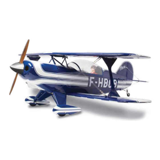
S-2B INSTRUCTION MANUAL For Intermediate and Advance pilots only All pictures and specifications shown in this manual are subject to change without notice. - Page 3 S-2B Thank you for purchasing your Kingcraft Pitts S-2B ARF model. We hope you enjoy assembling and flying it as much as we did creating it. This super scale model was created in the true spirit of Curtiss Pitts, it is very straightforward to build and fun to fly, all the hardwork has been done for you.
- Page 4 S-2B TOOL REQUIRED / REQUIRED ITEMS Ruler Clear Tape Hobby Knife Hex Driver 1.5mm 2.5mm Phillips Screwdriver Drill Bit - 2mm Pliers Thread Lock Thin/Thick CA 5 Min Epoxy Aerodrive LiPo Charger SK3 3548 840kv 6+ Channel Transmitter + Receiver 4S 4300-5000 mah Aerostar 70A Electronic 4* 17g Servos...
- Page 5 B’ A’ A=A’ B=B’ C=C’ D=D’ D’ C’...
- Page 6 S-2B AIRFRAME ASSEMBLY 1. Wing assembly components and hardware 2. Take the supplied small balsa block with an opening slot shown in Pic. A. Then sand the balsa block according to the shape of that supplied triangle shape template and this will perfectly match the turtle deck shape.
- Page 7 3. Connect some servo extension leads to your aileron servos and screw the servos into the servo bays in the lower wings using self tapping screws. Fit the ailerons to the wings using the supplied hinges and epoxy or CA glue. Ensure the ailerons move freely with no friction once the glue has set. 4.
- Page 8 S-2B 6. First slide the wing joining rod into the wing joiner tube and secure it with 5min epoxy. Join the 2 wing halves together using 30 min epoxy and put aside until it has set. 7. Test fit the bottom wing to the fuselage and use the supplied screws and wing mount reinforcement plate to secure the wing onto the fuselage.
- Page 9 9. Install u-shaped rigging mounts to the top wing. Carefully cut open all the wing center cabane struts access holes and openings on the fuselage as shown in the pictures above. 10. Use epoxy or CA glue to secure the metal rings to the cross struts. Install the front, rear and cross aluminum wing struts as shown.
- Page 10 S-2B 12. Trial fit the inter-plane struts to the wings. Then use the supplied screws to lock the inter-plane struts and make sure the tabs are fully seated into the wings. Ensure the top/bottom wings are straight and true to the fuselage and without any stress or distortion to the wings. Then epoxy the tabs into the wings when everything fits and lines up perfectly.
- Page 11 15. Prepare rigging clevis assembly and attach it to the top wing rigging mount tabs, do this to both sides. 16. Thread the rigging wires through the rigging mounting tab on the top wing at the center rear. Prepare rigging clevis then attach it to the bottom wing rigging mounting tabs, do this to both sides. 17.
- Page 12 S-2B 18. Insert the landing gear suspension assembly into the aluminum tube provided. Then install landing suspension struts to the landing gear as shown in the pictures above. 19. Install the landing gear axle and suspension assembly to the aluminum landing gear plate at the same time.
- Page 13 21. Hardware for the tail assembly. Trial fit the stabiliser onto the fuselage tail section. Ensure the stabiliser is true, square and level. Mark the area’s which are going to be glued on the tail section and remove the covering so that you are bonding wood with wood, not to the covering. 22.
- Page 14 S-2B 24. According to your marks use a knife to carve a slot and drill a hole for the U-shaped rod installation as shown above. 25. Epoxy glue the U-shaped rod to the elevator halves and ensure the halves stay perfectly flat without twisting whilst the glue sets.
- Page 15 27. Check the alignment of the fin then glue into place. Check alignment then hinge the rudder to the fin with epoxy or CA glue. 28. Glue the control horns to the elevator and rudder with epoxy or CA glue. 29.
- Page 16 S-2B 30. Tape a small piece of cardboard paper on the elevator and rudder to protect the film covering while you are going to work on the thread coupler soldering. Solder the pushrod to the thread coupler fitting on the other end of the push rod. Then attach it to the rudder and elevator control horns. 31 Tail wheel assembly.
- Page 17 33. Attach the tension spring to the rudder steering arm and the tail wheel control arm. 34. Attach rigging struts to the fin and stabiliser as shown. 35. Cowling and motor mount assembly parts. Secure the motor mount with epoxy glue.
- Page 18 S-2B 36. Use the method shown to locate the mounting screws holes on cowling. Then install your preferred brushless motor onto the motor mount. The motor box has a built in 3 degrees of right thrust. Make sure the motor is offset a few millimetres to the left so as to bring the motor shaft back to center of the cowl when it has been installed.
- Page 19 39. Glue the small white box and the white tubing fittings into place as shown. 40. Glue the pilot into place. Use silicon glue to secure the front dash board into place as shown. 41. Glue the rear dash board into place with silicon glue.
- Page 20 S-2B 42. Canopy locking mechanism assembly. (Picture A) (Picture B) (Picture C) 43. Sand the supplied small balsa block with an opening slot shown in picture A below, sand according to the small triangle shape template supplied in the pack. Note: Please follow picture B below for the correct orientation of the balsa blocks curvature surface.
- Page 21 (Picture A) (Picture B) 45. Use a sharp knife to cut an opening in the covering film according to the slot on the balsa block as shown in picture A. Glue the plastic lock mechanism to the balsa block by using epoxy as shown in Picture B.
- Page 22 S-2B Check all control surfaces are moving in the correct direction with the applicable stick input (see below) Roll left Aileron (Roll) Ailerons v+/-23mm Expo: 15-20% Roll right Pitch up Elevator (Pitch) Elevators +/-15mm Expo: 15-20% Pitch down Yaw left Rudder (Yaw) Rudder +/-25mm Expo: 15-20%...
-
Page 23: Flying Tips
If you have trimmed it properly, you are able to fly the Pitts S-2B... - Page 24 S-2B...
- Page 26 S-2B...
Need help?
Do you have a question about the PITTS S-2B and is the answer not in the manual?
Questions and answers