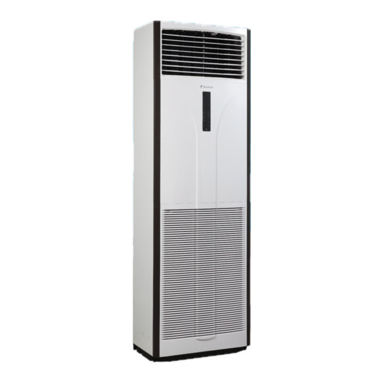
Daikin R410A Technical Manual
Floor standing
Hide thumbs
Also See for R410A:
- Installation manual ,
- Service manual (381 pages) ,
- Owner's manual (40 pages)
Table of Contents
Advertisement
Advertisement
Table of Contents

Related Manuals for Daikin R410A


Summary of Contents for Daikin R410A
- Page 1 Floor Standing TECH NI CAL MANUAL TM-FVN-0515-A...
-
Page 2: Table Of Contents
Table of Contents 1. Model Name ......................1 2. Features ........................ 2 3. Specifications ......................3 4. Sound Data ......................4 5. Application Information ..................6 Operating Range ..................6 Refrigerant Circuit Diagrams ..............7 Controllers ....................8 6. Installations ......................13 7. Wiring Diagrams ....................30 8. Servicing & Maintenance ..................33 9. Troubleshooting .................... -
Page 3: Model Name
V1 : Single Phase, 220-240V, 50Hz Series A : A Series Capacity Index 30 : Based On Btu/hr Refrigerant N : R410A Type Of Air-Conditioner FV : Floor Standing Outdoor Power Supply V1 : Single Phase, 220-240V, 50Hz Y1 : Three Phase, 380-415V, 50Hz... -
Page 4: Features
2. Features Modern And Stylish Design Daikin R410A floor standing unit is designed with stylish profile and classy control panel which is easily to blend in any interior environment. Setting Control Method Daikin floor standing unit can be controlled by using two methods: a. setting by pressing the control panel on the unit b. setting by using the wireless controller (standard) Aesthetic Black Control Panel The control panel is come with large button for ease of use. It provides a white LED light for clear display when switched on. Ion Plasma Generator Ion plasma generator remove airborne contaminates from the air we breathe, and thus create a refreshing environment. -
Page 5: Specifications
NOMINAL RUNNING CURRENT, 1ø [3ø] 13.0 [7.07] [8.23] [9.35] Btu/hr / W 9.86 9.88 9.62 10.02 REFRIGERANT CONTROL OUTDOOR CAP.TUBE REFRIGERANT TYPE R410A POWER SOURCE V/Ph/Hz 220-240/1/50 380-415/3/50 VERTICAL AUTOMATIC LOUVER DISCHARGE CONTROL HORIZONTAL MANUAL OPERATION CONTROL PANEL OR WIRELESS REMOTE CONTROL... - Page 6 Specifications INDOOR UNIT FVN30AV1L FVN40AV1L FVN50AV1L FVN60AV1L MODEL OUTDOOR UNIT RN28CV1 RN40DY1 RN50DY1 RN61DY1 AIR FLOW l/s / CFM 684 / 1450 1604 / 3400 2171 / 4600 SOUND PRESSURE LEVEL HEIGHT mm / in 753 / 29.6 852 / 33.5 UNIT DIMENSION WIDTH mm / in...
-
Page 7: Sound Data
4. Sound Data Sound Pressure Level 1/1 Octave Sound Pressure (dB, ref20µPa) Overall Noise Model Speed (dBA) Criteria 125Hz 250Hz 500Hz 1kHz 2kHz 4kHz 8kHz High FVN30AV1L High FVN40AV1L High FVN50AV1L High FVN60AV1L Model Measuring Location Microphone FVN30AV1L Indoor FVN40AV1L unit FVN50AV1L FVN60AV1L Standard: JIS C 9612... -
Page 8: Application Information
5. Application Information Operating Range Ensure the operating temperature is in allowable range. Cooling Only Outdoor DB (°C) Caution : The use of your air conditioner outside the range of working temperature and humidity can result in serious failure. Indoor WB (°C) -
Page 9: Refrigerant Circuit Diagrams
Refrigerant Circuit Diagrams Model: FVN30AV1L-RN28CV1 Model: FVN40AV1L-RN40DY1 / FVN50AV1L-RN50DY1 FVN60AV1L-RN61DY1... -
Page 10: Controllers
Controller DGS01 TURBO QUIET SLEEP MODE TIMER CANCEL CLOCK CANCEL Operating Guide Transmission Source • The source where the signal will be transmitted. Signal Transmission Indication • Blink to confirm that the last setting has been transmitted to the unit. “ON/OFF”... - Page 11 Turbo function • Press for fast cooling operation. • Fan speed turn to maximum speed. • Press again to deactivate the function. • Available under COOL and DRY modes only. • Any change of fan speed will deactivate this function. Quiet function •...
-
Page 12: Operating Guide
DSLM8 MODE TURBO SWING QUIET TIMER TIMER TIMER OVERRIDE SLEEP Operating Guide MODE Button Press the MODE button to switch operation from COOL, AUTO*, DRY*, FAN. Check the display to see in which mode the control is set. *AUTO and DRY are available for selected models only. TURBO Fan Speed Press the Turbo key once to activate Turbo fan speed. - Page 13 “ON TIMER” and “OFF TIMER” The unit has 2-event timer, namely Timer 1 and Timer 2, each event has an ON TIMER and an OFF TIMER. The key press activity for Timer ON and Timer OFF is shown on Table 1.1 Table 1.1: Timer ON and Timer OFF key press and event sequence.
- Page 14 OVERRIDE Function Press the OVERRIDE key once will activate the override function for 1 hour. An indicator “OVERRIDE 1” will show on the LCD. Press the same key again will increase the setting to 2 hours. An indicator “OVERRIDE 2” will be shown. Subsequent press will deactivate the override function. After the override timer is completed, the override function is deactivated and the logo is OFF.
-
Page 15: Installations
5. Installations Installation Guideline CAUTION Sharp edges and coil surface are potential injury hazard. Avoid from contact with them. Installation Diagram Indoor Unit Air Discharge Louver Signal Receiver Indicator Lights Air Intake Grille Air Filters (Inside Air Intake Grille) Wrap the insulated pipe with the finishing tape from bottom to top Air Intake Air Intake... -
Page 16: Installation Of The Indoor Unit
Installation Of The Indoor Unit Preliminary Site Survey Be sure to read this manual before installing the air-conditioner indoor unit. • Voltage supply fluctuation must not exceed +10% of rated voltage. Electricity supply lines must be independent of welding transformers which can cause high supply fluctuation. •... -
Page 17: Indoor Unit Installation
Indoor Unit Installation Fixing Procedure • Fix the indoor unit by using embedded bolt, etc. to prevent falling down of the vertically-long shaped unit. 1. Detach the air intake grille. Remove the screw (Right, Left, total 2) holding the grille. Then, (1) lean the grille forward you, and (2) lift upward and out. - Page 18 < Method 2 > Fix the indoor unit to the floor with Anchor bolts (to be locally procured) using fixing holes (x4) on the bottom frame. All dimensions are in mm 57, (79) 144, (202) <Bottom> Fixing Hole (x 4) * Dimension in ( ) for 40-60 models.
- Page 19 <In case of rear piping> 1. Open the holes on the rear panel. (Refer to Figure G). 2. Pass refrigerant pipes, drain pipes, and unit wiring through the hole on the rear panel. <In case of downward piping> 1. Cut holes in the indicated area of the bottom frame. (Refer to Figure G). 2.
-
Page 20: Drain Piping Work
Drain Piping Work 1. Rig the drain piping. Rig the drain line to ensure proper drainage. Also, observe the following to prevent leaks. Drain hose inside the unit Fan housing Bottom Frame Liquid pipe Anchor hose here Gas pipe Drain hose (Procure in field). Vinyl Tube (Pipe size 20mm). - Page 21 Intake Grille Intake grille must be installed as step below. 1. Hook the air intake grille on the groove on the unit’s bottom frame in order of (1) -> (2). (Refer to Figure J). Figure J 2. Fit the grille stopper (front panel) into the groove on the air intake grille and lock the grille down in its original place by screw.
- Page 22 Filter Cleaning work 1. Take out the filter from the unit in order of (1) -> (2). (Refer to Figure L). Figure L 2. Clean the filter, either use a vacuum cleaner , or wash them in water and dry in the shade. 3.
-
Page 23: Installation Of The Outdoor Unit
Installation Of The Outdoor Unit As condensing temperature rises, evaporating temperature rises and cooling capacity drops. In order to achieve maximum cooling capacity, the location selected for outdoor unit should fulfill the following requirements: • Install the condensing (outdoor) unit in a way such that the hot air distributed by the outdoor condensing unit cannot be drawn in again (as in the case of short circuit of hot discharge air). -
Page 24: Cable Size
Outdoor Clearance Avoid installing or operating the condensing unit in the environment that is exposed to the following substances: • Oils (including machine oils) • Salt (e.g. coastal area) • Sulphide gas (e.g. hot spring areas, oil refinery plant, etc) Such substances may lead to the failure of the unit. - Page 25 • All wires must be firmly connected. • Make sure all the wire do not touch the refrigerant pipings, compressor or any moving parts. • The connecting wire between the indoor unit and the outdoor unit must be clamped by using provided cord anchorage.
- Page 26 Piping Works And Flaring Technique • Do not use contaminated or damaged copper tubing. If any pipings, evaporator or condenser had been exposed or had been opened for 15 seconds or more, the system must be vacuumed. Generally, do not remove plastic, rubber plugs and brass nuts from the valves, fittings, tubings and coils until it is ready to connect suction or liquid line into valves or fittings.
-
Page 27: Vacuuming And Charging
R410A. pipes correctly. Never use copper pipes thinner than • POE or PVE oil is used as lubricant for R410A 0.8mm even though they are available in the market. compressor, which is different from the mineral oil •... -
Page 28: Refrigerant Piping Work
If the piping length is more than 7.5m then use the additional charge value as indicated in the table. Additional refrigerant charge [g] per additional 1m length as tabulated (for R410A models) FVN30AV1L FVN40AV1L... - Page 29 Special Precautions When Charging Unit With Scroll Compressor These precautions are intended for use with Scroll compressors only with R22, and R410A refrigerants but are not applied to reciprocating compressors or competitive Scroll compressors. Scroll compressors have a very high volumetric efficiency and quickly pump a deep vacuum if there is insufficient refrigerant in the system or if refrigerant is added too slowly.
-
Page 30: Indicator Lights
2. Charging procedures – Three phase compressors The fundamental procedure is the same as for single phase models but the compressor can run in the wrong direction on starting. If this happens reverse any two phases and start again. Short term reverse rotation will not damage the compressor. - Page 31 Phase Sequential (3ph) The unit with Scroll Compressor can only rotate in one direction. For this reason, a protective device (phase sequential) is fitted to prevent incorrect wiring of the electrical phases. When the three phases are not connected correctly, the phase sequential operates, and the unit will not start. This device is located in the control box of the outdoor unit.
-
Page 32: Wiring Diagrams
6. Wiring Diagrams Indoor Unit Model : FVN30AV1L Outdoor Unit Model : RN28CV1... - Page 33 Indoor Unit Outdoor Unit Model : FVN40/50AV1L Model : RN40/50DY1...
- Page 34 Indoor Unit Outdoor Unit Model : FVN60AV1L Model : RN61DY1...
-
Page 35: Servicing & Maintenance
7. Servicing and Maintenance Warning • Disconnect from main supply before servicing the air conditioner. • The unit is designed to give long life operation with minimum maintenance required. However, it should be regularly checked and the following items should be given due attention. At least once every 2 1. - Page 36 Pre start up maintenance (After extended shutdown) • Inspect thoroughly and clean indoor and outdoor units. • Clean or replace air filters. • Clean condensate drain line. • Clean clogged indoor and outdoor coils. • Check fan imbalance before operation. •...
-
Page 37: Troubleshooting
8. Troubleshooting Error Code / Fault Condition When a malfunction of the air conditioner unit is detected, immediately switch off the main power supply before proceeding with the following troubleshooting procedures. The following are common fault conditions and simple troubleshooting tips. If any other fault conditions which are not listed occur, contact your nearest local dealer. - Page 38 Diagnostic Guidelines By means of pressure reading : Pressure Data Probable cause Circuit High side ● 1. Overcharged with refrigerant. Low side ● 2. Non-condensable gases in refrigerant circuit (e.g. air) 3. Obstructed air-intake / discharge. 4. Hot air short circuiting in outdoor unit. High side ●...
-
Page 39: Dimensional Data
9. Dimensional Data Indoor Unit Model: FVN 30/40/50/60AV1L Dimension Model FVN30AV1L 1850 FVN40/50/60AV1L 1850 Dimension in mm... -
Page 40: Outdoor Unit
Outdoor Unit Model : RN28CV1 All dimensions are in mm Dimension Model RN28CV1 Dimension Model RN28CV1 Model : RN40/50/61DY1 All dimensions are in mm Dimension Model RN 40/50/61DY1 1030 826 400 695 746 142... -
Page 41: Exploded View & Part List
10. Exploded View & Part List Indoor Unit Model: FVN 30/40/50/60AV1L PARTS DESCRIPTION PARTS DESCRIPTION ASSY. COIL ASSY. FRONT PANEL ASSY. DISPLAY PANEL FRONT ASSY. DISCHARGE FRAME PANEL CONTROL MODULE VANE, VERTICAL ASSY. CONTROL BOX LOUVER, HORIZONTAL COVER CONTROL BOX ASSY. INTAKE GRILLE MOTOR CONNECTOR, INTAKE GRILLE BLOWER FAN HOLDER, AIR FILTER LEFT ASSY. - Page 42 Outdoor Unit Model : RN28CV1 PARTS DESCRIPTION PARTS DESCRIPTION ASSY., BASE PAN TOP PANEL ASSY., OUTDOOR COIL ASSY., CONTROL PANEL TERMINAL COVER PANEL MOTOR BRACKET ASSY., VALVE COVER FAN MOTOR FAN BLADE ASSY., FRONT GRILLE VALVE BRACKET PLASTIC HANDLE, SIDE PARTITION DISCHARGE PIPE COMPRESSOR...
-
Page 43: High
Model : RN40/50/61DY1 PARTS DESCRIPTION PARTS DESCRIPTION MOTOR BRACKET ASSY., BASE PAN FAN MOTOR ASSY., COIL ASSY., FRONT PANEL PALTE, FLARE VALVE ASSY., CONTROL PANEL FLARE VALVE 3/8” SERVICE PANEL FLARE VALVE 5/8” FAN BLADE PARTITION TOP PANEL COMPRESSOR PLASTIC HANDLE ACCUMULATOR PARTS NOT IN THE DIAGRAMS ASSY., CAPILLARY TUBE... - Page 44 . c o m . m y GROUP ASSOCIATED (C&L) SDN BHD (109719-M) Head Office: Tel: 03-7953 8388 Fax: 03-7956 4371 Email: sales_enquiry@daikin.com.my, customer_service@daikin.com.my Branches: • Penang Tel: 04-331 1670 • Johor Tel: 07-557 7788 •...
Need help?
Do you have a question about the R410A and is the answer not in the manual?
Questions and answers