
Related Manuals for UEi DMEG3/IRT3


Summary of Contents for UEi DMEG3/IRT3
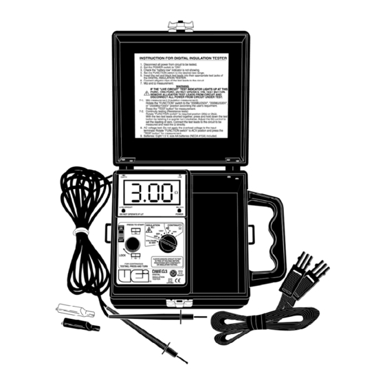
- Page 1 INSTRUCTION MANUAL DMEG3/IRT3 1-800-547-5740 • Fax: (503) 643-6322 www.ueitest.com • email: info@ueitest.com...
-
Page 2: Table Of Contents
TABLE OF CONTENTS Introduction ..................1 Safety .......................2 International Symbols ..............5 Controls Power Switch ...................6 Rotary Function Select Switch ............6 Press to Test ..................6 Resistance Null Adjust ..............6 Indicators LCD Display ..................8 Power On Indicator ................8 Live Circuit Indicator ..............8 Operation Installing Test Leads ...............9 Detecting AC Voltage ..............10 Measuring AC Voltage ..............11... -
Page 3: Introduction
Introduction Your UEi Megohmeter allows you to predict, prevent and identify insulation failures that can cause appliance failure, stop production, create power problems and even put lives at risk. It quickly tests insulation integrity on motors, power distribution systems and other installed wiring. -
Page 4: Safety
• DO NOT attempt to use this meter if either the meter or the test leads have been damaged. Return the damaged meter to UEi for repair or replace your test leads • Ensure meter leads are fully seated and operable by... - Page 5 This meter was designed for use by service professionals who know the hazards associated with their trade. Exceeding the specified limits of this meter is dangerous and can cause serious injury. To ensure safe and appropriate use, please observe the following safety guidelines: •...
- Page 6 Higher voltages require greater awareness of physical safety hazards. When it’s possible to make clip-on connections to the circuit under test, make the connections without power applied: 1. Turn off the power to the circuit under test. 2. Set the meter to the AC 600 Volt position. 3.
-
Page 7: International Symbols
International Symbols... - Page 8 Controls and Indicators (IRT3) (DMEG3)
-
Page 9: Power Switch
1. Power Switch: Turns instrument power off and on. 2. Rotary Function Select Switch: Selects measurement mode and scale. 3. Press to Test: Press this button down to initiate any measurement function. Turn to the right while pressing to lock the button into the test mode. 4. -
Page 10: Lcd Display
Analog Display (IRT3) (Fig 1) Live circuit Power ON LCD Display (DMEG3) (Fig 2) IRT3 (Fig 1) • Red light indicates that the “Press to Test” switch is pressed • Voltage is tested without pressing “Press to Test” switch DMEG3 (Fig 2) •... -
Page 11: Installing Test Leads
Replace batteries if needed (refer to the maintenance section of this manual). If there is any damage to the instrument, it must be returned to UEi for repair. Installing Test Leads Test leads must be installed prior to any measurement or detection procedure. -
Page 12: Detecting Ac Voltage
Detecting AC Voltage Any time AC voltage is present on the test leads, the “Live Circuit” indicator light will illuminate. This voltage detection feature works regardless of battery condition or powering on the instrument. With test leads installed: 1. Ensure power is off (DMEG3) and the Press to Test is NOT pressed. -
Page 13: Measuring Ac Voltage
Measuring AC Voltage Voltage levels of up to 600 volts AC can be measured with your insulation resistance tester. With test leads installed: 1. Ensure power is on (DMEG3). 2. Place rotary function select switch to the “AC 600 V” position. 3. -
Page 14: Measuring Continuity
Measuring Continuity Continuity testing allows you to quickly determine if two or more points are connected electrically and it allows you to check for excessive resistance across contacts. With its high resolution, you can compare input to output windings on transformers or help identify a motor-type by checking the resistance of its windings. -
Page 15: Measuring Insulation Resistance
Measuring Insulation Resistance Insulation resistance testing (IRT) is the process of evaluating an insulating material’s integrity. Any time you use IRT procedures; you will be applying a relatively high DC voltage (250, 500 or 1000 Volts) to two separate conducting paths. For example, the “conducting paths”... - Page 16 You will commonly find IRT procedures performed in these tasks: • Predictive/preventive maintenance on installed motor windings - recommended for all motors 750 watts (1 HP) or greater • Predictive/preventive maintenance on commercial HVAC compressors • Testing integrity of insulation on buried cables powering well-pumps •...
- Page 17 Humidity and dew point information is available for some areas by phone (see your local listing). UEi also makes special purpose instruments to give you accurate and instant humidity, dew point and temperature information.
-
Page 18: Temperature Correction
Temperature Correction Temperature has a very large impact on your insulation resistance values. When using your meter for predictive or preventive maintenance tasks, the readings must be “temperature corrected” to 20˚C (68˚F). The rule of thumb is, insulation resistance changes by a factor of 2 for every 10 degrees of change in Celsius-scaled temperature. - Page 19 Multiply By (Fig 3) NOTE: UEi makes a number of temperature products to use in reading motor temperatures.
-
Page 20: Preparing Equipment Under Test
Preparing Equipment Under Test Isolation is a key factor in properly testing any insulation resistance value. Whether you are testing a motor winding, transformer winding or a cable, you must ensure that the component you are evaluating has no path to ground or other circuits. - Page 21 When more than one connection is called for, connect the test points together. E = Earth L = Line Single Phase Transformer Connection Sequence Table Sequence Ground Motor Connection Sequence Table Sequence Stator Field Ground Insulated 3-Conductor Cable Connection Sequence Table Sequence Shielded 3-Conductor Cable Connection Sequence Table Sequence...
- Page 22 60-Second (spot reading) Method Spot readings are often used as predictive/preventive maintenance tools. Readings are generally taken at regular intervals (quarterly, semi-annually, etc.) and recorded on a chart that stays with the equipment being tested. To make an analysis of a motor using this method: 1.
- Page 23 8. At the end of 60-seconds, read and record the insulation resistance value. 9. Apply temperature correction factor and record results on PM Chart (Fig 4). This chart interprets some possible data. Megohms (Fig 3)
- Page 24 Extended Term Analysis These methods incorporate comparisons of resistance values recorded at different points of time (up to ten minutes). They can provide useful information about the condition of your equipment even if PM records are not available. Generally speaking, the resistance measured at the end of 5 or 10 minutes should be higher than it was at one minute.
-
Page 25: To Make An Extended Term Analysis
To Make An Extended Term Analysis 1. Check and record equipment temperature. 2. Check dew point temperature of the ambient air - equipment under test must be above dew point temperature for accurate results. 3. Ensure no power is applied to the equipment under test and all connections are removed in order to totally isolate the motor, cables or equipment form other circuits. - Page 26 INSULATION RESISTANCE DATA LOG CARD EQUIPMENT MAKE SER. NO. LOCATION PLACED IN SERVICE COMMENTS DATE INFINITY 1000...
- Page 27 TEMPERATURE PLOT ADJUSTED READING RELATIVE DATE READING HUMIDITY AMBIENT EQUIP. CORRECTION ADJUSTED FACTOR READING...
-
Page 28: Maintenance
All servicing is to be accomplished by UEi. Annual calibration is recommended and can be conducted by a local calibration facility or at UEi’s factory headquarters in Beaverton, Oregon. Cleaning The external surfaces and empty battery compartment should be inspected for dirt and contamination on a regular basis. -
Page 29: Fuse Replacement
To replace the batteries, turn the instrument upside down on a clean, flat surface to expose battery compartment. 1. Remove the battery cover retaining screw. 2. Apply outward pressure (away from the carrying handle) on the battery cover and remove it from the instrument. 3. -
Page 30: Specifications
To replace the fuse, turn the instrument upside down on a clean, flat surface to expose battery compartment. 1. Remove the battery cover retaining screw. 2. Apply outward pressure (away from the carrying handle) on the battery cover and remove it from the instrument. 3. - Page 31 2. AC Voltage Range 0-600V Resolution Accuracy ±1.5% reading ±3 digit Line frequency 40-120 Hz. range 3. Continuity Ohm range 0-20Ω / Resolution: 0.01Ω / Accuracy: ±1.5% rdg. ±5 dgt. Ohm range 0-2000Ω / Resolution: 1Ω / Accuracy: ±1.5% rdg. ±3 dgt. Open circuit 4 DC min.
- Page 32 Specifications (IRT3) 1. Insulation resistance 0-50MΩ & ∞ (250 DC V ±10%) Megohm 0-100MΩ & ∞ (500 DC V ±10%) 0-200MΩ & ∞ (1000 DC V ±10%) Accuracy ±5% of indicated value (approximately) Short circuit 0-50MΩ : 2 DCmA terminal 0-100MΩ...
- Page 33 4. Maximum Voltage Meet IEC-1010 safety requirements Catagory III 5. Dimension 6.7 x 6.5 x 3.6 inches (170 x 165 x 92 mm) with housing front cover 6. Weight 2.1 lb. (batteries included)
-
Page 34: Limited Warranty
DMEG3/IRT3 Insulation Resistance Tester Limited Warranty The DMEG3/IRT3 is warranted to be free from defects in materials and workmanship for a period of three years from the date of purchase. If within the warranty period your instrument should become inoperative from such defects, the unit will be repaired or replaced at UEi’s option.
Need help?
Do you have a question about the DMEG3/IRT3 and is the answer not in the manual?
Questions and answers