Table of Contents
Advertisement
Quick Links
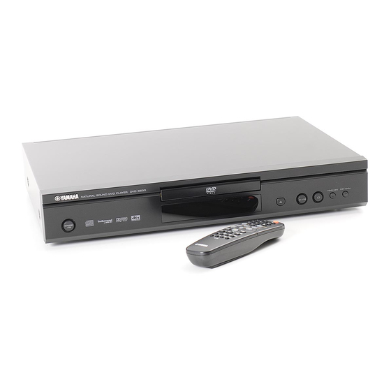
DVD-S530/DV-S5550
This manual has been provided for the use of authorized YAMAHA Retailers and their service personnel.
It has been assumed that basic service procedures inherent to the industry, and more specifically YAMAHA Products, are already
known and understood by the users, and have therefore not been restated.
WARNING:
IMPORTANT:
The data provided is believed to be accurate and applicable to the unit(s) indicated on the cover. The research, engineering, and
service departments of YAMAHA are continually striving to improve YAMAHA products. Modifications are, therefore, inevitable
and specifications are subject to change without notice or obligation to retrofit. Should any discrepancy appear to exist, please
contact the distributor's Service Division.
WARNING:
IMPORTANT:
CONTENTS
To Service Personnel ...................................... 2~3
Prevention Of Electro Static Discharge ............. 4
Locale Management Information ................... 4
Front Panels ............................................................ 5
Remote Control ...................................................... 6
Rear Panels .......................................................... 6~7
Specifications .......................................................... 8
Service Hints ............................................................ 9
Disassembly Procedures ................................. 10
DIAGNOSTIC SOFTWARE AND
TROUBLESHOOTING ........................................... 11~19
1 0 0 8 1 7
SERVICE MANUAL
IMPORTANT NOTICE
Failure to follow appropriate service and safety procedures when servicing this product may result in personal
injury, destruction of expensive components, and failure of the product to perform as specified. For these reasons,
we advise all YAMAHA product owners that any service required should be performed by an authorized
YAMAHA Retailer or the appointed service representative.
The presentation or sale of this manual to any individual or firm does not constitute authorization, certification or
recognition of any applicable technical capabilities, or establish a principle-agent relationship of any form.
Static discharges can destroy expensive components. Discharge any static electricity your body may have
accumulated by grounding yourself to the ground buss in the unit (heavy gauge black wires connect to this buss).
Turn the unit OFF during disassembly and part replacement. Recheck all work before you apply power to the unit.
TEST INSTRUCTION FRONT DISPLAY AND
AUDIO/VIDEO BOARD .......................................... 20~21
Circuit Descriptions ..................................... 22~28
Abbreviation List ................................................. 29
TECHNICAL SPECIFICATIONS DVD MODULE ............ 30
Ic Descriptions ................................................ 31~39
Wiring Diagram ...................................................... 40
Block Diagram ....................................................... 41
Printed Circuit Board .................................. 42~59
Schematic Diagram ........................................ 60~74
Parts List ........................................................... 75~82
Remote Control .................................................... 83
DVD-S530/DV-S5550
DVD PLAYER
P.O.Box 1, Hamamatsu, Japan
1
Advertisement
Table of Contents

Related Manuals for Yamaha DVD-S530


Summary of Contents for Yamaha DVD-S530
-
Page 1: Dvd Player
This manual has been provided for the use of authorized YAMAHA Retailers and their service personnel. It has been assumed that basic service procedures inherent to the industry, and more specifically YAMAHA Products, are already known and understood by the users, and have therefore not been restated. -
Page 2: To Service Personnel
DVD-S530/DV-S5550 TO SERVICE PERSONNEL AC LEAKAGE WALL EQUIPMENT TESTER OR 1. Critical Components Information OUTLET UNDER TEST EQUIVALENT Components having special characteristics are marked s and must be replaced with parts having specifications equal to those originally installed. 2. Leakage Current Measurement (For 120V Models Only) - Page 3 DVD-S530/DV-S5550 Laser Diode Properties Type: Semiconductor laser GaAlAs Wave length: 650 nm (DVD) 780 nm (VCD/CD) Output Power: 0.8 mW (DVD) 0.3 mW (VCD/CD) Beam divergence: 60 degree VARO! : AVATTAESSA JA SUOJALUKITUS OHITETTAESSA OLET ALTTIINA NÄkymÄTTÖMÄLLE LASER- SÄTEILYLLE. ÄLÄ KATSO SÄTEESEEN.
-
Page 4: Prevention Of Electro Static Discharge
DVD-S530/DV-S5550 PREVENTION OF ELECTRO STATIC DISCHARGE The laser diode in the DVD mechanism may be damaged due to static electricity from clothes or the human body. Use caution to prevent electrostatic damage when servicing or handling the DVD-mechanism. 1. Grounding for electrostatic damage prevention Some devices, such as the DVD player, use an optical pickup (laser diode) that will be damaged by static electricity in the working environment. -
Page 5: Front Panels
DVD-S530/DV-S5550 FRONT PANELS DVD-S530 DV-S5550 REMOTE CONTROL... -
Page 6: Rear Panels
DVD-S530/DV-S5550 REAR PANELS DVD-S530 U, C models DVD-S530 R model DVD-S530 A model DVD-S530 B, G models DVD-S530 P model... - Page 7 DVD-S530/DV-S5550 DVD-S530 K model DV-S5550 U, C model DV-S5550 A model DV-S5550 G model...
-
Page 8: Specifications
DVD-S530/DV-S5550 SPECIFICATIONS PLAYBACK SYSTEM CONNECTIONS DVD Video Y Output Cinch (green) (U, C, R, A, P, K) DVD+RW Pb/Cb Output Cinch (blue) (U, C, R, A, P, K) DVD+R Pr/Cr Output Cinch (red) (U, C, R, A, P, K) Video CD and SVCD... -
Page 9: Service Hints
DVD-S530/DV-S5550 SERVICE HINTS Service Positions Power Supply Unit Refer to dismantling instructions for dismounting of the The power supply unit has to be replaced in case of board. Fig. 3 shows the service position that are failure. The schematic provided in the manual is only for recommended during repair of the boards. -
Page 10: Disassembly Procedures
DVD-S530/DV-S5550 DISASSEMBLY PROCEDURES See exploded view for item numbers. Top Cover 21 Mounting Remove 7 screws 31. Lift cover from rearside to Dismounting remove. Front panel ass'y 1 DVD mechanism 9 Monoboard 11 Remove cable connections. Remove flex and cable Remove flex and cable Open Tray (see instruction below). -
Page 11: Troubleshooting
DVD-S530/DV-S5550 DIAGNOSTIC SOFTWARE AND TROUBLESHOOTING 1. Dealer Script 1.2 Contents of Dealer Script 1.1 Purpose of Dealer Script The dealer script executes all diagnostic nuclei that do not The dealer script can give a diagnosis on a standalone need any user interaction and are meaningful on a DVD player, no other equipment is needed to perform a standalone DVD player. -
Page 12: Remote Control
DVD-S530/DV-S5550 2. Player Script 2.4 Survey 2.1 Purpose of Player Script The Player script will give the opportunity to perform a test Press 2 keys simultaneously <OPEN/CLOSE> + <STOP> that will determine which of the DVD player's modules are Connect to mains faulty, to read the error log and error bits and to perform an endurance loop test. - Page 13 DVD-S530/DV-S5550 3. Display PCB If any keys are detected more than once (due to hardware 3.1 Display Test error), the key-code is displayed twice (or more), with the The display test is performed by nucleus DispDisplay. By second digit increased by 1.
- Page 14 DVD-S530/DV-S5550 In this example 23 is the hexidecimal code of the pressed After pressing PLAY, the result of the remote control test is RC key. The user can leave the remote-control test by displayed on the local display of the DVD player as pressing PLAY on the local keyboard of the DVD player.
- Page 15 DVD-S530/DV-S5550 4. Mono PCB Digital Part 4.3 Sound 2 Test 4.1 Picture Test The second soundtest is performed by producing a sine The picture test is performed by putting a predefined sound (nucleus AudioSineOn). The signal can be stopped p i c t u r e ( c o l o r b a r ) o n t h e d i s p l a y ( n u c l e u s by pressing the STOP key.
- Page 16 DVD-S530/DV-S5550 5. Basic Engine By pressing OPEN/CLOSE the user confirms that the disc 5.1 Version Number motor is running. Pressing STOP indicates the disc motor In the basic engine tests, the version number of the Basic does not work. Pressing PLAY proceeds to the next test, Engine will be shown first, as the following example: after a reset of the disc motor (nucleus BeDiscMotorOff).
- Page 17 DVD-S530/DV-S5550 that this test will not contribute to the test result of the (respectively) through the logged errorcodes. If the display Basic Engine. Pressing PLAY proceeds to the next test, only shows "EB-0", no error bits were set. By pressing after the disc motor has been shut off with a call to nucleus PLAY the user can continue to the next test.
- Page 18 DVD-S530/DV-S5550 6.1 Errorlog Error Explanation: Number Error name Explanation The application errors will be logged in the NVRAM. The 0103 S2B_SLEDGE Sledge could not be moved to home position. maximum number of error bytes that will be visible is 16.
- Page 19 DVD-S530/DV-S5550 SSM Error Codes SMA Error Codes Error Error Code Error name Explanation Number Error name Explanation 0006 SP_SYNCER System cannot get synchronized 0000 SMA_TIMEO Data coming from disc not in with sectors coming from disc. UTERROR time. Reason: damaged disc or Reason: Usually a damaged engine problem.
- Page 20 DVD-S530/DV-S5550 TEST INSTRUCTION FRONT DISPLAY AND AUDIO/VIDEO BOARD 1. General 3. Audio DAC And Amplifier • All the waveforms measurement carried out in these Ensure that the Audio mute signal is OFF test instruction will be based on the testpoint indicated...
- Page 21 DVD-S530/DV-S5550 8. Front Display ll waveforms can be refered to the A/V board schematic diagram. To check the segment display of the FTD, the following command can be used. And for full detail description of the 5. Play and 16/9 Detection test, refer to the chapter of “Diagnostic Software Player...
-
Page 22: Audio/Video Board
DVD-S530/DV-S5550 CIRCUIT DESCRIPTIONS 1. Introduction 2.2 Output Voltages 2. Power Supply PSU Connection 3. Control and Display A/V BOARD 4. Audio/Video (A/V) and SCART +3V3STDBY 5. Loader/Mono Board +3V3STDBY +12VSTDBY 8p cable Notes: +5VSTDBY • Figures can deviate slightly from the actual model. - Page 23 DVD-S530/DV-S5550 The -8V is regulated to -5.5V via transistor 7304 and Primary Current Sensing zenerdiode 6308, and is switched 'off', with transistor The current through FET 7125 will result in a voltage drop 7305, during Standby Mode. across R3120/21/22 (RSENSE). This line goes to pin 11 of The -32V is not switched 'off' during Standby Mode.
- Page 24 DVD-S530/DV-S5550 The slave processor has an internal square signal Status Truth Table generator (42 kHz), to generate the AC filament voltage. SCART_0 STBY_CTRL 0|6|12 Function 4:3 aspect ratio DVD TS7105/7103 and 7106 amplify the square signal before it TV display is applied to the display (VAC= VFIL_1 - VFIL_2, VRMSùï...
- Page 25 DVD-S530/DV-S5550 • KILL_LR: This is a signal from the audio DAC, when it In the SD3.0 module, the servo signals were fed to the receives no input for a certain time (8192 LRCK cycles). MACE2 servo processor, while the HF output signal was It can be tested in STOP, PAUSE and during track fed to the SAA7335 decoder.
- Page 26 DVD-S530/DV-S5550 The spindle-motor interface provides both motor control Processor Overview signals from the demodulator and, in addition, contains a Function STi5580 STi5588 STi5519 tachometer loop that accepts tachometer pulses from the Basic CD/VCD/DVD decoding Extra 2-channel of I2S output (PCMDATA3) motor unit.
- Page 27 DVD-S530/DV-S5550 External Memory Miscellaneous I/O Signals The STi55xx family is capable of accessing external Most general IO ports are connected directly to the memory via three buses: module interface. • The enhanced memory interface (EMI). This interface is configurable and can be used to access SCART Flash, ROM, and various types of DRAM.
- Page 28 DVD-S530/DV-S5550 5.4 Power Supply (Diagram M7) SD4.0 Power Supply Block Diagram Front-end motor driver Front-end 3.3V Front-end regulator 3.3V (optional) 3.3V Back-end 3.3V 2.5V / 1.8V Back-end regulator 2.5V / 1.8V Fig. 12 The main power supplies to the module are 3.3V, 5V, and 12V (input via connector 1701).
- Page 29 DVD-S530/DV-S5550 ABBREVIATION LIST Analog to Digital Converter Serial Clock I2C Amplitude Modulation SCLK Audio serial bit clock Basic Engine Serial Data I2C ComPair Computer aided rePair SDRAM Synchronous DRAM CD-DA CD Digital Audio S/PDIF Sony Philips Digital InterFace Chip Select...
- Page 30 DVD-S530/DV-S5550 TECHNICAL SPECIFICATIONS OF DVD MODULE Connections 4. Connector 1703: Digital Video Connector. 1. Connector 1701: Basic Connector 1. GND 1. I2CSCL/SIOCLK 2. YC0 2. I2CSDA/SIODATA 3. GND 3. SCART1 4. YC1 4. SCART0 5. GND 5. AGND 6. YC2 6.
-
Page 31: Ic Descriptions
DVD-S530/DV-S5550 IC DESCRIPTIONS TZA1033 DVDALAS2plus Advanced Analog DVD Signal Processor and Laser Supply Diode Amplifiers Balanced Processing Data & header Interface Header Land Servo Signals Push Pull Land/Groove D1-D6 Swap Offset Mute compensations 3 Beam Tracking V & I references... - Page 32 DVD-S530/DV-S5550 TZA1033 DVDALAS2plus Advanced Analog DVD Signal Processor and Laser Supply CD-A CD-B CD-C CD-D CD-REF VDDA4 CD-E VSSA4 CD-F VDDA1 VSSA1 O-CENTRAL DVD-MI LPF-DPD2 LPF-DPD1 DVD-A DVD-B FTC-REF DVD-C DVD-D DVD-REF MXXxxx Pin description Name Description CD-A CD pick up input A...
- Page 33 DVD-S530/DV-S5550 TZA1033 DVDALAS2plus Advanced Analog DVD Signal Processor and Laser Supply Name Description O-central Test pin for offset cancelation Internally connected FTC-ref Servo output voltage reference input Servo current output for radial tracking Servo current output for radial tracking Internally connected Fast track count voltage output pos.
- Page 34 DVD-S530/DV-S5550 SAA7812HL Front-end Processor Channel decoder Block decoder/ CD/DVD Erco encoder DRAM interface drive Host Bit Detector Memory Pro c & Demodulator interface interface Memory Proc Erco Motor/ multimedia Tach o interface interface subcode interface modu le control cpu interface...
- Page 35 DVD-S530/DV-S5550 SAA7812HL Front-end Processor DASP DAC_RP DA2_GRD DAC_RN DAC_VPOS PDIAG DAC_VNEG DA1_GWR DAC_LP IOCS16 DAC_LN INTRQ TEST1 DMACK_GRQ TEST2 IORDY CRIN DIOR CROUT DIOW DMARQ_GACK HFIN_DN SAA7812 M3x HFIN_DP DD15 HFIN_SE Iguana VCOM DD14 IREF WREFLO DD13 TEST3 DD12 SIN_PHI...
- Page 36 DVD-S530/DV-S5550 STI5519 Back end Host Processor 2 UART & Internal peripherals 2 SmartCards Central CACHE SUBSYSTEM command port (C2+) Front-end & link interface Clock DMAs ICache generator SRAM Refill control DCache Diagnostic JTAG controller debugging interface CPU arbiter Communications arbiter...
- Page 37 DVD-S530/DV-S5550 STI5519 Back end Host Processor PIO2[5] CPU_DATA[13] PIO2[6] CPU_DATA[12] PIO2[7] CPU_DATA[11] VDD3_3 CPU_DATA[10] CPU_DATA[9] PIO3[0] CPU_DATA[8] PIO3[1] PIO3[2] VDD2_5 PIO3[3] CPU_DATA[7] PIO3[4] CPU_DATA[6] PIO3[5] CPU_DATA[5] PIO3[6] CPU_DATA[4] PIO3[7] CPU_DATA[3] VDD2_5 CPU_DATA[2] CPU_DATA[1] B_DATA CPU_DATA[0] B_BCLK CPU_CAS1 B_FLAG CPU_CAS0 B_SYNC...
- Page 38 DVD-S530/DV-S5550 Am29LV160BT 16 MB (2 M x 8-bit / 1 M x 16-bit) CMOS 3.0 Volt-only Sector Erase Flash Memory – DQ15 (A-1) RY/BY# Sector Switches Erase Voltage Input/Output RESET# Generator Buffers State Control BYTE# Command Register PGM Voltage Generator...
-
Page 39: Power Supply
DVD-S530/DV-S5550 TY72011P2 Power Supply Vcc pin13 Startup UVLOh = 15V Over Voltage UVLOl = 7.2V Protection (Vcc > 41V?) Internal Vcc Internal regulator Last pulse of demag after 4µs Demag DEMAG ? Internal Clamp Verr max = 3V Clock Verr min = 10mV... -
Page 40: Wiring Diagram
DVD-S530/DV-S5550 WIRING DIAGRAM... -
Page 41: Block Diagram
DVD-S530/DV-S5550 BLOCK DIAGRAM SERVICE SERIAL FLEX CABLE INTERFACE CONN. 1501 CONN. 1703 1700 SERVICE VSYNC PCMDATA1-3 HSYNC TXD_SER RXD_SER 27M_CLK RTS_SER CTS_SER 7501 7605 HFN,HFP OPTION RESET 74HCT14D 1130 7600 SERVICE 1100 STi5519 RSTNB TXD_BE SCART [0:1] SCART[0:1] RXD_BE PROGRAMMABLE... -
Page 42: Printed Circuit Board
DVD-S530/DV-S5550 MONO-Board Top View (Overview) PRINTED CIRCUIT BOARD 1100 A2 2720 A3 3309 A1 3788 D3 PART 1 1210 B2 2721 A3 3310 A1 3789 D3 1300 A2 2722 A3 3311 A1 3790 D3 1301 A1 2724 B3 3314 A1... - Page 43 DVD-S530/DV-S5550 PRINTED CIRCUIT BOARD MONO-Board Detailed Top View Part 1 PART 1...
- Page 44 DVD-S530/DV-S5550 PRINTED CIRCUIT BOARD MONO-Board Detailed Top View Part 2 PART 2...
- Page 45 DVD-S530/DV-S5550 MONO-Board Bottom View (Overview) PRINTED CIRCUIT BOARD 2102 A2 2625 C1 3232 B2 3703 B1 7104 A2 PART 1 2103 A2 2626 C2 3233 B2 3704 B1 7201 B2 2106 A2 2627 C2 3234 B2 3706 B1 7202 B2...
- Page 46 DVD-S530/DV-S5550 PRINTED CIRCUIT BOARD MONO-Board Detailed Bottom View Part 1 PART 1...
- Page 47 DVD-S530/DV-S5550 PRINTED CIRCUIT BOARD MONO-Board Detailed Bottom View Part 2 PART 2...
- Page 48 DVD-S530/DV-S5550 MONO-Board Testpoint Overview PRINTED CIRCUIT BOARD F100 B1 F171 A2 F271 A1 F503 D3 F708 A1 F787 A1 F101 B2 F172 B2 F272 B2 F504 D3 F709 A1 F788 A1 F102 B2 F173 B2 F273 B3 F505 C3 F710 A1...
- Page 49 DVD-S530/DV-S5550 PRINTED CIRCUIT BOARD (G, B models) AV-Board (Top View) 1003 1140 2162 2231 2306 7218 9707 9714 9724 9731 9738 9745 9752 9761 9768 1100 1230 2163 2235 2310 9701 9708 9715 9725 9732 9739 9746 9753 9762 9769...
- Page 50 DVD-S530/DV-S5550 PRINTED CIRCUIT BOARD (G, B models) AV-Board (Bottom View) 2104 B3 2161 B4 2222 B5 2316 A4 3145 B4 3168 B1 3203 A4 3233 A4 3304 A3 3425 A5 4802 A7 4829 A4 6102 B2 7163 B1 7306 A3...
- Page 51 DVD-S530/DV-S5550 PRINTED CIRCUIT BOARD (G, B models) AV-Board Bottom View Part 1 PART1...
- Page 52 DVD-S530/DV-S5550 PRINTED CIRCUIT BOARD (G, B models) AV-Board Bottom View Part 2 PART2...
- Page 53 DVD-S530/DV-S5550 PRINTED CIRCUIT BOARD (G, B models) AV-Board Testpoint Overview I101 B2 I125 A2 I139 B3 I154 B3 I176 B3 I195 B4 I211 B7 I224 B7 I237 A5 I251 A1 I315 A4 I331 B5 I102 B2 I126 B1 I140 A2...
- Page 54 DVD-S530/DV-S5550 PRINTED CIRCUIT BOARD (U, C, A, R, T, P models) AV-Board (Top View)
- Page 55 DVD-S530/DV-S5550 PRINTED CIRCUIT BOARD (U, C, A, R, T, P models) AV-Board (Bottom View)
- Page 56 DVD-S530/DV-S5550 PRINTED CIRCUIT BOARD Display-Board (Top View) 1100 A2 1105 A8 1110 C21 1115 C3 2106 A9 2129 B1 7110 A11 1101 A3 1106 A6 1112 A10 1116 A22 2123 B2 2133 B22 1102 C8 1107 A21 1113 B15 1117 C6...
- Page 57 DVD-S530/DV-S5550 PRINTED CIRCUIT BOARD Display-Board Bottom View Part 1 PART 1...
- Page 58 DVD-S530/DV-S5550 PRINTED CIRCUIT BOARD Display-Board Bottom View Part 2 PART 2...
- Page 59 DVD-S530/DV-S5550 PRINTED CIRCUIT BOARD Standby-Board (Top View) 1200 A2 1201 B1 Standby Board TO 1116 of DISPLAY PANEL STANDBY 1200 STBKEY+ 1201 STBKEY- 440053 Standby-Board (Bottom View) /usr2/part/mg/audio/DVD_2002/panels/ 3139_243_30451_01/8239_2TO_92200 1201...
-
Page 60: Schematic Diagram
DVD-S530/DV-S5550 SCHEMATIC DIAGRAM 1100 D1 F127 F2 2100 A10 F128 D11 2101 B9 F129 D11 2102 B2 F130 F2 2103 B5 F131 E11 2104 B9 F132 F2 Front-end processor and Laser supply - DVDalas 2 2105 B11 F133 F2 2106 B3... - Page 61 DVD-S530/DV-S5550 SCHEMATIC DIAGRAM 3282 H3 1200 A2 T218 E14 5200 B2 1210 D1 T219 E13 2200 A7 5201 C2 T220 E14 2201 B7 5202 F1 T221 E13 5203 E11 2202 B3 T222 E14 +3V3DF 2203 A7 5204 E11 Front-end 2204 B7...
- Page 62 DVD-S530/DV-S5550 SCHEMATIC DIAGRAM 1300 D1 1301 A1 1303 H1 2300 A8 2301 C3 2302 B10 Front-end Loader Interface +5VDF 2303 C11 2304 C10 2305 E7 2300 2306 E7 2308 H9 7301 100n F325 2309 H12 BA6665FM 3300 1301 12V7 2311 I2...
- Page 63 DVD-S530/DV-S5550 SCHEMATIC DIAGRAM 2401 B7 2402 B4 2410 B10 2411 B12 2412 C10 2413 C12 Back end - MEMORY 2414 C10 2415 C12 2416 C12 2417 H14 3402 F1 3420 C12 3425 G13 3426 G13 3427 F8 3428 E1 3429 F1...
- Page 64 DVD-S530/DV-S5550 SCHEMATIC DIAGRAM 1501 E6 2502 B2 2503 B3 2508 B2 2509 B3 2514 C2 Back-end SDRAM and SERVICE INTERFACE 2515 C3 2520 C2 2521 D9 2522 D7 2523 F8 3500 C1 3521 B9 3522 B9 3523 B9 Back-end HOST PROCESSOR...
- Page 65 DVD-S530/DV-S5550 SCHEMATIC DIAGRAM 1600 C10 F637 C8 2603 B3 F641 G14 2604 B4 F642 G14 2605 B9 F643 G14 2606 C12 F644 G14 2607 C12 F645 G14 2608 C13 F646 G14 Back end 2609 C13 F647 D9 +3V3DB 2610 B11...
- Page 66 DVD-S530/DV-S5550 SCHEMATIC DIAGRAM C58 H5 3753 I9 F736 F10 C59 H5 3755 D8 F737 F12 C60 H5 3756 D9 F738 F8 C61 H5 3757 D9 F739 F9 C63 H5 3758 D9 F740 A9 1702 1700 Back-end C64 H5 3759 D10...
- Page 67 DVD-S530/DV-S5550 SCHEMATIC DIAGRAM (G, B models) 1003 H12 7134 C8 1100 E1 7150 G2 1102 F1 7151 H2 VIDEO & SCART 1103 B13 7160 H5 1130 B10 7161 I5 1140-A E11 7162 I6 1231 I3 7163 G6 2104 H10 7164 F5...
- Page 68 DVD-S530/DV-S5550 SCHEMATIC DIAGRAM (G, B models) 1104 F1 1140-B E13 1140-C B13 1230 I13 AUDIO 2201 C2 2202 G13 2203 D5 2204 E5 2205 B9 +5V_DAC 2237 2206 C9 +5VM 2207 E9 diagram 100n 2208 D7 2209 A7 I211 2210 F8...
- Page 69 DVD-S530/DV-S5550 SCHEMATIC DIAGRAM (G, B models) 1101 D1 2301 C3 2302 D8 2303 D3 Regulated Supply 2304 C8 2306 B2 2307 E3 2310 E8 2311 E8 A1-27 2314 D4 MUTE A2-27 2315 F3 +3V3STBY 2316 F3 7309 +3V3 2317 E6...
- Page 70 DVD-S530/DV-S5550 SCHEMATIC DIAGRAM (U, C, A, R, T, P models) 1003 C12 1100 E1 1102 F1 1105-A F12 VIDEO & SCART 1105-B H12 1105-C E12 1140-A A11 1231 H3 2103 H3 2104 C10 SUB_WOOFER/ 2105 D10 2107 F1 I170 1140-A...
- Page 71 DVD-S530/DV-S5550 SCHEMATIC DIAGRAM (U, C, A, R, T, P models) 1104 F1 1140-B A13 1140-C D13 +5VM 1230 H13 AUDIO 2201 C2 2202 G13 100n 2203 A7 I226 +5V_DAC 2237 3240 200R 2203 3213 2204 A7 4415 LM833D 2207 D9...
- Page 72 DVD-S530/DV-S5550 SCHEMATIC DIAGRAM (U, C, A, R, T, P models) 1101 D1 I327 E3 2301 C3 I328 B6 2302 D9 I329 E8 2303 D3 I330 E9 2304 C8 I331 D9 Regulated Supply 2306 B2 I332 B7 2307 E3 I333 B7...
-
Page 73: Display Panel
DVD-S530/DV-S5550 SCHEMATIC DIAGRAM 1100 C11 1101 E12 1102 C12 1103 G1 1105 D12 +5Vstb For models with P50 only 1106 D11 DISPLAY PANEL 3160 1107 D11 1108 D12 3103 3105 3107 3108 FIL1 FIL2 1110 C11 1112 H7 1113 B5... - Page 74 DVD-S530/DV-S5550 SCHEMATIC DIAGRAM (G, B models only) 0100 A1 F236 D10 0101 B2 F237 D10 0200 D12 F240 E10 FOR INFORMATION ONLY (NO SERVICE PARTS WILL BE AVAILABLE) 0201 F12 F241 E10 0203 F10 F255 A10 1110 A2 F256 A10...
-
Page 75: Parts List
DVD-S530/DV-S5550 WARNING PARTS LIST Components having special characteristics are marked s and must be replaced with parts having specifications equal to those originally in- stalled. ELECTRICAL PARTS For the parts No. of the chip carbon resistors, refer to last page of ELECTRICAL PARTS LIST. - Page 76 DVD-S530/DV-S5550 P. C. B. MONO Schm Schm Ref. PART NO. Description Remarks Ref. PART NO. Description Remarks AAX39610 MONO BOARD(UCRATPK) 3139 248 82211 2236 US062100 C.CE.CHP 100pF AAX39600 MONO BOARD (GB) 3139 247 10631 2300 US135100 C.CE.CHP 0.1uF 1210 AAX39910 RSNR.CRYS 8.4672MHz 2422 543 01242 2301 US135100 C.CE.CHP...
- Page 77 DVD-S530/DV-S5550 P. C. B. MONO & P. C. B. AV (U, C, R, A, T, P, K models Schm Schm Ref. PART NO. Description Remarks Ref. PART NO. Description Remarks 2713 UF138100 C.EL.CHP 100uF 7710 AAX22740 TR.CHP BC847B 4822 130 60511 2714 US135100 C.CE.CHP...
- Page 78 DVD-S530/DV-S5550 P. C. B. AV (B, G models) Schm Schm Ref. PART NO. Description Remarks Ref. PART NO. Description Remarks 2307 US135100 C.CE.CHP 0.1uF 2201 UR847470 C.EL 47uF 2310 UR848100 C.EL 100uF 2202 US135100 C.CE.CHP 0.1uF 2311 US135100 C.CE.CHP 0.1uF 2203 US135100 C.CE.CHP...
- Page 79 DVD-S530/DV-S5550 P. C. B. AV (B, G models) & P. C. B. DISPLAY Schm Schm Ref. PART NO. Description Remarks Ref. PART NO. Description Remarks 7211 AAX21660 IC LM833D 4822 209 30095 RD350000 R.CAR.CHP 0Ω 1/10W 7212 AAX21660 IC LM833D 4822 209 30095 RD353100 R.CAR.CHP 1Ω...
- Page 80 DVD-S530/DV-S5550 EXPLODED VIEW When disassembling, use the special screw driver with tip shape in figure. 2.7 mm Note) The Lid is not available.
-
Page 81: Mechanical Parts
DVD-S530/DV-S5550 MECHANICAL PARTS Ref. PART NO. Description Remarks Markets AAX39510 FRONT PANEL ASS'Y S530BL 3139 247 56201 UCPA AAX41990 FRONT PANEL ASS'Y S530BL 3139 247 57451 AAX39500 FRONT PANEL ASS'Y S530GD 3139 247 56191 AAX41970 FRONT PANEL ASS'Y S530GD 3139 247 57431... - Page 82 DVD-S530/DV-S5550 Ref. PART NO. Description Remarks Markets ACCESSORY AAX39870 REMOTE CONTROL RC19133010/00 3139 238 02571 AAX23450 AUDIO/VIDEO CABLE YE/RD/WH 1.5m 1pc 2422 076 00304 UCRTPKA AAX21980 AUDIO PIN CABLE RD/WH 1.5m 1pc 3103 308 92611 AAX22970 VIDEO CABLE 1.5m 1pc...
- Page 83 DVD-S530/DV-S5550 REMOTE CONTROL VBAT OPTION OPTION OPTION Screened Resistor 1001 2001 SPRING 7001 100n Jumper PLUS 6001 M34282 options OPTION LTE-3271AL 2 x AA 4006 Batteries CARR 1002 3001 SPRING MINUS XOUT 4001 7002 BC337-25 4002 5001 4003 CSTS 4MHz...
- Page 84 DVD-S530/DV-S5550...
Need help?
Do you have a question about the DVD-S530 and is the answer not in the manual?
Questions and answers