Makita DUC121 Technical Information
14.4v/ 18v cordless chain saw 115mm (4-1/2)
Hide thumbs
Also See for DUC121:
- Instruction manual (104 pages) ,
- Instruction manual (93 pages) ,
- Instruction manual (120 pages)
Table of Contents
Advertisement
Quick Links
Download this manual
See also:
Instruction Manual
T
ECHNICAL INFORMATION
Model No.
Description
C
ONCEPT AND MAIN APPLICATIONS
Models DUC121 and DUC122 are cordless chain saws powered by
the following Li-ion battery;
DUC121 (14.4V): BL1415N (1.5Ah), BL1415NA (1.5Ah), BL1430 (3.0Ah),
BL1430A (3.0Ah), BL1440 (4.0Ah) and BL1450 (5.0Ah)
DUC122 (18V): BL1815N (1.5Ah), BL1820 (2.0Ah), BL1830 (3.0Ah),
BL1840 (4.0Ah) and BL1850 (5.0Ah)
These models feature higher operation efficiency and more convenience
than the current 12V Model UC120D.
Note: These products are not compatible with 1.3Ah battery BL1415/ BL1815.
S
pecification
Specification
Voltage: V
Capacity: Ah
Battery
Cell
Energy capacity: Wh
Charging time (approx.): min.
Cutting length: mm (")
Chain speed: m/s (m/min.)
Chain blade
Chain brake
Weight according to
EPTA-Procedure 01/2003*
*1 With Guide bar, Saw chain
*2 With Battery BL1430, BL1440 or BL1450
*3 With Battery BL1830, BL1840 or BL1850
S
tandard equipment
Battery*
4
Battery cover*
5
Charger*
4
Plastic carrying case*
*4 Battery, Charger and Plastic carrying case are not supplied with "Z" model
*5 Supplied with the same quantity of extra battery
Note: The standard equipment may vary by country or model variation.
O
ptional accessories
Chain blade 25AP-42E
Guide bar
Pruning extension set
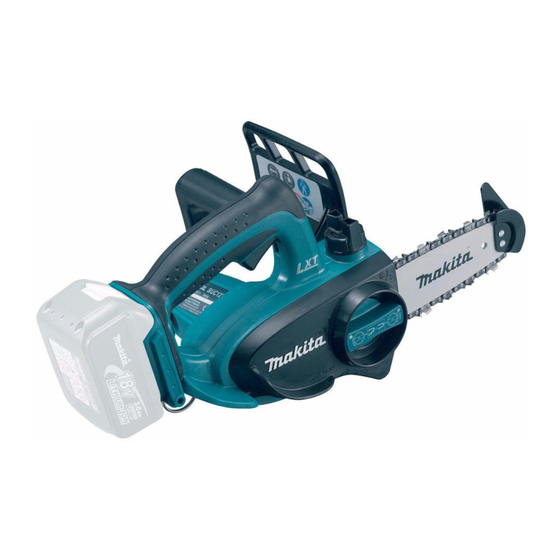
DUC121/ DUC122
14.4V/ 18V Cordless Chain Saw 115mm (4-1/2)
Model
15, 22, 36, 45 with DC18RC
Type
Pitch
: kg (lbs)
1
File
Oil supply (containing 100ml of chain oil)
Guide bar cover
4
Fast charger DC18RC
Charger DC18SD/DC24SC
Automotive charger DC18SE
Four port multi charger DC18SF
Two port multi fast charger DC18RD
DUC121
14.4
1.5, 3.0, 4.0, 5.0
Li-ion
22, 44, 58, 72
115 (4-1/2)
4.8 (290)
25AP-42E
1/4"
Yes (Electric brake)
2.5 (5.4) *
2
For DUC121
Battery BL1415N
Battery BL1415NA
Battery BL1430
Battery BL1430A
Battery BL1440
Battery BL1450
OFFICIAL USE
for ASC & Sales Shop
PRODUCT
P 1/ 8
L
H
W
Dimensions: mm (")
Length (L)
422 (16-5/8)
Width (W)
195 (7-5/8)
Height (H)
215 (8-1/2)
DUC122
18
1.5, 2.0, 3.0, 4.0, 5.0
27, 36, 54, 72, 90
15, 24, 22, 36, 45 with DC18RC
5.0 (300)
2.6 (5.7) *
3
For DUC122
Battery BL1815N
Battery BL1820
Battery BL1830
Battery BL1840
Battery BL1850
Advertisement
Table of Contents

Related Manuals for Makita DUC121


Summary of Contents for Makita DUC121
- Page 1 DUC121/ DUC122 Description 14.4V/ 18V Cordless Chain Saw 115mm (4-1/2) ONCEPT AND MAIN APPLICATIONS Models DUC121 and DUC122 are cordless chain saws powered by the following Li-ion battery; DUC121 (14.4V): BL1415N (1.5Ah), BL1415NA (1.5Ah), BL1430 (3.0Ah), Dimensions: mm (") BL1430A (3.0Ah), BL1440 (4.0Ah) and BL1450 (5.0Ah)
- Page 2 [2] LUBRICATION To protect parts and product from unusual abrasion; 1) apply 7g of Makita grease FA No. 2 to Gear room. Note: Be sure to apply a little amount of the above grease to the inner periphery of Crank.
- Page 3 P 3 / 8 epair [3] DISASSEMBLY/ ASSEMBLY (cont.) [3]-2. Disassembling/ Assembling Gear Section DISASSEMBLING 1) Remove Stop ring E-8 from Spindle then remove Sprocket 9 and Lock washer 12. 2) Loosen four 4x18 Tapping screws (Fig. 3) then strike Spindle end using plastic hammer. (Fig. 4) Bearing housing can be removed.
- Page 4 2) Pull off Crank and check if O ring 1.5 on its end of pin portion has damaged or not. 3) Pour approx. 30cc of Makita genuine chain oil (Refer to LUBRICANT) or commercial oil VG32-100 to Oil tank. Rise and fall Crank by hand while checking if Chain oil is delivered from chain oil exit designated by arrow in Fig.
- Page 5 P 5 / 8 epair [3] DISASSEMBLY / ASSEMBLY (cont.) [3]-5. Disassembling/ Assembling Filter in Handle R DISASSEMBLING Fig. 11 1) Strike the center of Push nut gently using Phillips screwdriver No.2 (Fig. 11), Phillips Push nut can be removed, and Filter can be picked out of chain oil exit of screwdriver No.
- Page 6 P 6 / 8 epair [3] DISASSEMBLY / ASSEMBLY [3]-6. Disassembling/ Assembling Motor Section (cont.) Fig. 14 ASSEMBLING Notch of Yoke 1) When mounting Yoke on Motor housing R, fit the notch of Yoke into the protrusion of Motor housing R. (Fig. 14) 2) Insert Armature gear shaft to gear room of Handle R, and fix Motor housing to Handle R by tightening 4x30 Tapping screws (4 pcs.).
- Page 7 P 7 / 8 ircuit diagram Fig. D-1 Color index of lead wires' sheath Black White Pass Lead wires through Switch Line filter one by one. Yellow Line filter (if used) Terminal Endbell complete Controller iring diagram Fig. D-2 Lead wire holder Endbell complete Fix Lead wires for Endbell complete with Lead wire holders.
- Page 8 P 8 / 8 iring diagram Fig. D-3 Fix Lead wires from Endbell complete and Lead wires between Switch and Terminal in each Lead wire holder as drawn below. Switch Lead wire holders Terminal Lead wire holder Line filter (if used) Pass Lead wires through Line filter one by one.
Need help?
Do you have a question about the DUC121 and is the answer not in the manual?
Questions and answers