Table of Contents
Advertisement
R-1330/
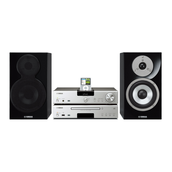
The MCS-1330 consists of the R-1330, CD-1330 and NS-BP400.
This service manual is for the R-1330/NS-BP400.
For service manual of the CD-1330, please refer to the following publication number:
MCS-1330 は、R-1330、CD-1330 および NS-BP400 で構成されています。
このサービスマニュアルは R-1330/NS-BP400 用です。
CD-1330 用のサービスマニュアルは下記管理ナンバーを参照してください。
This manual has been provided for the use of authorized YAMAHA Retailers and their service personnel.
It has been assumed that basic service procedures inherent to the industry, and more specifi cally YAMAHA Products, are already known
and understood by the users, and have therefore not been restated.
WARNING:
IMPORTANT:
The data provided is believed to be accurate and applicable to the unit(s) indicated on the cover. The research, engineering, and service
departments of YAMAHA are continually striving to improve YAMAHA products. Modifications are, therefore, inevitable and
specifi cations are subject to change without notice or obligation to retrofi t. Should any discrepancy appear to exist, please contact the
distributor's Service Division.
WARNING:
IMPORTANT:
■ CONTENTS
TO SERVICE PERSONNEL ........................................2-4
PREVENTION OF ELECTROSTATIC DISCHARGE ......5
SYSTEM COMPOSITION / システム構成 .......................6
FRONT PANELS .............................................................6
REAR PANELS ...........................................................7-8
REMOTE CONTROL PANELS ...................................7-8
SPECIFICATIONS / 参考仕様 .........................................9
INTERNAL VIEW .......................................................... 10
DISASSEMBLY PROCEDURES / 分解手順 ........... 11-13
TEST MODE / テストモード ................................... 14-15
MICRO COMPONENT SYSTEM
CD-1330: 101130
CD-1330: 101130
IMPORTANT NOTICE
Failure to follow appropriate service and safety procedures when servicing this product may result in personal injury,
destruction of expensive components, and failure of the product to perform as specifi ed. For these reasons, we advise
all YAMAHA product owners that any service required should be performed by an authorized YAMAHA Retailer or
the appointed service representative.
The presentation or sale of this manual to any individual or fi rm does not constitute authorization, certifi cation or
recognition of any applicable technical capabilities, or establish a principle-agent relationship of any form.
Static discharges can destroy expensive components. Discharge any static electricity your body may have
accumulated by grounding yourself to the ground buss in the unit (heavy gauge black wires connect to this buss).
Turn the unit OFF during disassembly and part replacement. Recheck all work before you apply power to the unit.
MCS-1330
RECEIVER/
NS-BP400
SERVICE MANUAL
UPDATING FIRMWARE /
ファームウェアの書き込み ..................................... 16-20
DISPLAY DATA .............................................................21
IC DATA ...................................................................22-27
PIN CONNECTION DIAGRAMS .............................28-29
BLOCK DIAGRAM ........................................................31
PRINTED CIRCUIT BOARDS .................................32-38
SCHEMATIC DIAGRAMS .......................................39-41
REPLACEMENT PARTS LIST ................................43-53
REMOTE CONTROL .....................................................54
SPEAKERS
Advertisement
Table of Contents

Related Manuals for Yamaha R-1330


Summary of Contents for Yamaha R-1330
-
Page 1: Table Of Contents
This manual has been provided for the use of authorized YAMAHA Retailers and their service personnel. It has been assumed that basic service procedures inherent to the industry, and more specifi cally YAMAHA Products, are already known and understood by the users, and have therefore not been restated. -
Page 2: To Service Personnel
R-1330/NS-BP400 ■ TO SERVICE PERSONNEL AC LEAKAGE 1. Critical Components Information WALL EQUIPMENT TESTER OR Components having special characteristics are marked OUTLET UNDER TEST EQUIVALENT must be replaced with parts having specifications equal to those originally installed. 2. Leakage Current Measurement (For 120V Models Only) -
Page 3: System Composition / システム構成
R-1330/NS-BP400 ■ SYSTEM COMPOSITION / システム構成 The MCS-1330 consists of the R-1330, CD-1330 and MCS-1330 は、R-1330、CD-1330 および NS-BP400 で NS-BP400. 構成されています。 MCS-1330 ▼ NS-BP400 ▼ NS-BP400 ▼ R-1330 ▼ CD-1330... -
Page 4: Front Panels
R-1330/NS-BP400 ■ FRONT PANELS R-1330 Top view Front view NS-BP400... -
Page 5: Rear Panels
R-1330/NS-BP400 ■ REAR PANELS R-1330 U model Bottom view T model K model... - Page 6 R-1330/NS-BP400 A model G model L model Bottom view...
- Page 7 R-1330/NS-BP400 J model NS-BP400 G, J models T model T model...
-
Page 8: Remote Control Panels
R-1330/NS-BP400 ■ REMOTE CONTROL PANELS RAX-22 RAX-21 (U, T, K, A, L, J models) (G model) -
Page 9: Specifications / 参考仕様
R-1330/NS-BP400 ■ SPECIFICATIONS / 参考仕様 R-1330 ■ Audio Section / オーディオ部 ■ FM Section / FM 部 Minimum RMS Output Power (Power Amp. Section) / Tuning Range / 受信周波数範囲 U model ............... 87.5 to 107.9 MHz 定格出力(パワーアンプ部) (L/R drive, 1 kHz, 0.5 % THD, LPF 20 kHz, 6 ohms) T, K, A, G, L models ......... - Page 10 R-1330/NS-BP400 NS-BP400 ■ Speaker Section / スピーカー部 Type / 形式 ........2-way bass reflex speaker system/ Dimensions (W x H x D) / 寸法(幅 × 高さ × 奥行き) Non magnetic shielding type / ....176 x 310 x 332.5 mm (6-15/16" x 12-3/16" x 13-1/16") 2 ウェイ・バスレフ/...
- Page 11 R-1330/NS-BP400 NS-BP400 111 (4-3/8") 11 (7/16") 70 (2-3/4") 169 (6-5/8") 300 (11-13/16") 176 (6-15/16") 332.5 (13-1/16") 15.5 (5/8") 17 (11/19") 1 screw hole A screw with a diameter of 4 mm can be used. 90 (3-9/16") [Hole depth: 10 (3/8")] Unit: mm (inch) 単位...
-
Page 12: Internal View
R-1330/NS-BP400 ■ INTERNAL VIEW Top view FRONT (2) P.C.B. FRONT (3) P.C.B. AM/FM Tuner MAIN (1) P.C.B. Power Transformer MAIN (2) P.C.B. FRONT (5) P.C.B. FRONT (1) P.C.B. FRONT (4) P.C.B. Front view... -
Page 13: Disassembly Procedures / 分解手順
R-1330/NS-BP400 ■ DISASSEMBLY PROCEDURES / 分解手順 (Remove parts in the order as numbered.) (番号順に部品を取り外してください。 ) Disconnect the power cable from the AC outlet. AC 電源コンセントから、電源コードを抜いてください。 1. Removal of Top Cover 1. トップカバーの外し方 ➀ ➁ ① のネジ 4 本、② のネジ 2 本を外します。 (Fig. 1)... - Page 14 R-1330/NS-BP400 3. Removal of AM/FM Tuner and MAIN (1) P.C.B. 3. AM/FM チューナー、MAIN (1) P.C.B. の外し方 ➅ Remove 2 screws ( ). (Fig. 2) ⑥ のネジ 2 本を外します。 (Fig. 2) b. Remove CB301. (Fig. 2) CB301 を外します。 (Fig. 2) Remove the AM/FM tuner. (Fig. 2) AM/FM チューナーを取り外します。...
- Page 15 R-1330/NS-BP400 When checking the P.C.B.s: P.C.B. をチェックする場合には: • Spread the rubber sheet and the cloth. Then place ・ ゴムシートと布を敷き、 その上にサブシャーシユニッ the sub chassis unit on the cloth and check it. (Fig. 3) トを置いてチェックします。 (Fig. 3) • Reconnect all cables (connectors) that have been ・...
-
Page 16: ファームウェアの書き込み
R-1330/NS-BP400 ■ UPDATING FIRMWARE / ファームウェアの書き込み After replacing the following parts update the latest firm- 下記の部品を交換した場合、下記の手順により最新の ware according to the following procedure. ファームウェアの書き込みを行ってください。 MAIN P.C.B. MAIN P.C.B. Microprocessor (IC50) of MAIN P.C.B. MAIN P.C.B. のマイコン(IC50) ● Required tools ● 必要なツール... - Page 17 R-1330/NS-BP400 ● Connection ● 接続 1. Set the switch (SW301) of RS232C conversion 1. RS232C 変 換 ア ダ プ タ ー の ス イ ッ チ(SW301) adapter to the “FLASH UCOM” position. (Fig. 1) FLASH UCOM 側に設定します。 (Fig. 1)...
- Page 18 R-1330/NS-BP400 ● Operation procedures ● 操作方法 1. Press the “ON/STANDBY, OFF” switch of this unit 1. 本機の ON/STANDBY、OFF スイッチを押して inward to the ON position. (Fig. 2) ON にします。 (Fig. 2) 2. Start up FlashSta.exe. (Fig. 2) 2. FlashSta.exe を起動します。 (Fig. 2)...
- Page 19 R-1330/NS-BP400 5. Click [Setting] and set the baud rate. (Fig. 4) 5. [Setting]をクリックし、通信速度の設定を行い ます。 (Fig. 4) Select 115200 bps for the baud rate and 40 ms for the program intervals. Reduce the baud rate if a transmission error occurs frequently.
- Page 20 R-1330/NS-BP400 8. When writing is completed, the screen appears 8. 書き込みが完了すると、 以下の画面が表示されます。 as shown below. (Fig. 6) [OK]をクリックします。 (Fig. 6) Click [OK]. (Fig. 6) 9. [Exit]をクリックし、FlashSta.exe を終了します。 9. Click [Exit] to end FlashSta.exe. (Fig. 6) (Fig. 6) Fig. 6 10. Check that the firmware version and checksum 10.
- Page 21 R-1330/NS-BP400 ● Initializing of this unit ● 本機の初期化 After updating firmware, be sure to initialize this ※ ファームウェアの書き込み後は、必ず本機を初期 unit. 化してください。 Start up the self-diagnostic function of this unit and 本機のダイアグを起動し、 「3. FACTORY PRESET」 メ select the “3. FACTORY PRESET” menu. (See “SELF- ニューを選択します。...
- Page 22 R-1330/NS-BP400 ■ SELF-DIAGNOSTIC FUNCTION / ダイアグ(自己診断機能) There are 9 main menu items, each of which has sub- メインメニューは 9 個あり、 そのそれぞれにサブメニュー menu items. Listed in the table below are menu items and があります。下表はメニュー一覧です。 sub-menu items. MAIN MENU SUB-MENU 1 VER/DEST/SUM...
- Page 23 R-1330/NS-BP400 ● Starting Self-Diagnostic Function ● ダイアグの起動 While pressing those 2 keys of this unit as indicated in 本機の下図に示す 2 つのキーを押しながら ON/STANDBY、 the figure below, press the “ON/STANDBY, OFF” switch to OFF スイッチを押して電源を入れます。 turn on the power. ダイアグが起動します。 The self-diagnostic function mode is activated.
- Page 24 R-1330/NS-BP400 CAUTION! 注意! Using this product with the protection function disabled プロテクションを解除した状態でのダイアグモードは、 may cause damage to itself. Use special care when us- 危険な状態でもプロテクションが作動しないため、動作 ing this mode. させると、機器を破壊することがあります。このモード を使用する場合は十分注意してください。 ● Canceling Self-Diagnostic Function ● ダイアグの解除 Before canceling self-diagnostic function, execute ダイアグを解除する前に、メインメニュー No. 3 の...
- Page 25 R-1330/NS-BP400 When there is a history of protection function due to デジタルアンプ部の電圧異常によるプロテクション履歴 abnormal voltage in the digital amplifier section. がある場合 P S D x x x A/D conversion value of voltage / 電圧の A/D 変換値 For details of protection functions, refer to the main menu プロテクションの詳細は、メインメニュー...
- Page 26 R-1330/NS-BP400 ● Operation procedure ● 操作 There are 9 menu items, each of having sub-menu items. ダイアグには 9 のメニューがあり、そのそれぞれにサブ メニューがあります。 Knob of this unit / 本機ツマミ Reverse Forward 逆送り 順送り Menu select メニューの選択 ● Functions in Self-Diagnostic Function ● ダイアグ中の機能...
- Page 27 R-1330/NS-BP400 ● Details of Self-Diagnostic Function menu ● ダイアグメニュー詳細 1. VER/DEST/SUM 1. VER/DEST/SUM The firmware version, destination and checksum are ファームウェアバージョン、仕向け、チェックサム displayed. を表示します。 The checksum is obtained by adding the data at every チェックサムは、プログラムエリア別にデータを 8 8 bits for each program area and expressing the result ビットごとに加算していき、4 桁の...
- Page 28 R-1330/NS-BP400 2. FL DISPLAY CHECK 2. FL DISPLAY CHECK This menu is used to check the FL display section and FL 表示部、インジケーターを確認します。 indicators. サブメニュー操作により、表示が以下のように変わ The display is changed as shown below by the sub- ります。 menu operation. 2-1. Initial display / 初期表示...
- Page 29 R-1330/NS-BP400 3. FACTORY PRESET 3. FACTORY PRESET This menu is used to reserve and inhibit initialization バックアップ用 IC(チューナープリセット等)の初 of the back-up IC (tuner preset, etc...). 期化を予約/禁止します。 Select this menu and press the “TUNING/PRESET ∧ ” 本メニュー選択後、 TUNING/PRESET ∧ キーを押し key to change display.
- Page 30 R-1330/NS-BP400 4. AD DATA CHECK 4. AD DATA CHECK This menu is used to display the A/D conversion 本機パネルキー、プロテクションなどを検出してい value of the main microprocessor which detects るメインマイコンの A/D 変換の値を、サブメニュー panel keys of this unit and protection functions in で表示します。 using the sub-menu.
- Page 31 R-1330/NS-BP400 4-4. SYSTEM CONNECTOR 4-4. SYSTEM CONNECTOR This menu is used to check the SYSTEM con- CD プ レ ー ヤ ー な し で SYSTEM コ ネ ク タ ー を nector without the CD player. チェックします。 With the power to this unit turned off, short 本機の電源を切った状態で、SYSTEM コネクター...
- Page 32 R-1330/NS-BP400 4-6. KEY/DEST 4-6. KEY/DEST (Panel key of this unit detection / Destination (本機のキー検出/仕向け検出) detection) マイコン(IC50)の 90 ピン(AD_KEY)の電圧 The voltage at 90 pin (AD_KEY) of microproces- 値を表示します。 sor IC50 is displayed. (基準電圧:5.0V=255) (Reference voltage: 5.0V=255) PURE DIRECT キー :ON(0 ∼ 13)...
- Page 33 R-1330/NS-BP400 5. PROTECTION HISTORY 5. PROTECTION HISTORY The history of protection function is displayed. プロテクション履歴を表示します。 5-0. DSP / RST 5 0 . H I S T D S P Select this menu and press the “TUNING/PRESET ∧ ” key to change display.
- Page 34 R-1330/NS-BP400 6. EEPROM CHECK 6. EEPROM CHECK Communication between microprocessor (IC50) and MAIN P.C.B. のマイコン(IC50)と EEPROM(IC52) EEPROM (IC52) on the MAIN P.C.B. is checked. の通信をチェックします。 OK : No error detected OK :不良検出なし NG : An error detected NG :不良検出あり 6 1 . E P R M : N G iPod ™...
- Page 35 R-1330/NS-BP400 8. AUDIO CHECK 8. AUDIO CHECK This menu is used to check the MUTE status and ミュートの状態、ボリュームレベルを確認します。 volume level setting. Audio MUTE ON 8 1 . A M U T O N Speaker relay OFF 8 2 . S P R Y O F F Phones MUTE ON 8 3 .
- Page 36 R-1330/NS-BP400 9. POWER OFF FACTOR HISTORY 9. POWER OFF FACTOR HISTORY The power off factor history is displayed. 電源オフ要因履歴を表示します。 Select this menu and press the “TUNING/PRESET ∧ ” 本メニュー選択後、 TUNING/PRESET ∧ キーを押し key to change display. て表示を切り替えます。 9-1 History 1 / 履歴 1 9 1 .
-
Page 37: Display Data
R-1330/NS-BP400 ■ DISPLAY DATA ● V801 : 12-ST-73GINK (FRONT (1) P.C.B.) ● PIN CONNECTION Pin No. Connection Pin No. Connection TSB TSA RESET OSC VDD PGND LGND Note: 1) F1, F2 ..Filament 2) NP ..No pin 3) NX ..No extended pin 4) DL .. -
Page 38: Ic Data
R-1330/NS-BP400 ■ IC DATA IC50: M3062LFGPFP (MAIN P.C.B.) Single-chip 16-bit microprocessor Port P0 Port P1 Port P2 Port P3 Port P4 Port P5 Port P6 <VCC2 ports> <VCC1 ports> Internal peripheral functions A/D converter System clock generation circuit (10-bit X 18-channels... - Page 39 R-1330/NS-BP400 Function Name Port Name Detail of Function SOUT4 DA_FL For FL driver control CLK4 CK_FL For FL driver control SYS_DM Set voltage output of system DIMMER N_DET_IP iPod detection SOUT3 MOTI_TU For TUNER control SIN3 MITO_TU For TUNER control...
- Page 40 R-1330/NS-BP400 Function Name Port Name Detail of Function STBY_LED For STANDBY LED control Vcc2 Microprocessor power supply +5 V No connected Microprocessor ground CE_SEL CE for selector CK_SEL Clock for selector DA_SEL Data for selector PWR_RY Power relay control STBY_CTRL...
-
Page 41: Pin Connection Diagrams
R-1330/NS-BP400 ■ PIN CONNECTION DIAGRAMS • ICs BA15218F IRS20957STRPBF LB1641 LM61CIZ LME49723MA LC72725KM-UY-TLM-E M24C08-RDW6TP M3062LFGPFP NJM2068MD NJM2388F05 1. V 2. V 3. GND 4. ON/OFF CONTROL NJM4580V-TE2 NJM78M12DL1A (TE1) NJW1111V RH5RE58AA-T1-FA NJW1194V NJM4580E 1: Vin 2: GND 1: INPUT 3: Vout... - Page 42 R-1330/NS-BP400 • Diodes MA8030-H 3.1V MA8110-L 10.7V 1N4002S 1SS355 D4SBN20-7101 MA8030-L 2.9V MA8130-M 13.0V MA8150-M 15.0V MA8039 3.9V MA8160-M 16.0V MA8047-M 4.7V MA8270-H 28.0V MA8051-L 5.0V Anode Anode MA8300-M 30.0V MA8051-M 5.1V Anode MA8056 5.6V MA8056-M 5.6V – MA8075-M 7.5V...
-
Page 43: Block Diagram
R-1330/NS-BP400 ■ BLOCK DIAGRAM AC IN → FRONT SCHEMATIC DIAGRAM PROCESSOR → MAIN SCHEMATIC DIAGRAM... -
Page 44: Printed Circuit Boards
R-1330/NS-BP400 ■ PRINTED CIRCUIT BOARDS FRONT (1) P.C.B. (Side A) POWER indicator INPUT PURE DIRECT indicator PHONES PURE JK801 TUNER PRESET DIRECT CB801 FRONT (2) P.C.B. (Side A) L model VOLTAGE MAIN (1) U, T, K, A, G, J models... - Page 45 R-1330/NS-BP400 FRONT (1) P.C.B. (Side B) FRONT (2) P.C.B. (Side B) • Semiconductor Location Ref no. Location Ref no. Location Q802 Q803 Q804 D802 Q805 D807 Q806 D808 Q807...
- Page 46 R-1330/NS-BP400 FRONT (3) P.C.B. FRONT (4) P.C.B. (Side A) (Side A) MAIN (1) (CB50) VOLUME G model CB302 CB301 G model +12MV MVOLG +5STBY AD_VOL AM/FM TUNER UP_MDRV DW_MDRY MAIN (1) (W50) FRONT (5) P.C.B. (Side A) ON/STANDBY / OFF •...
- Page 47 R-1330/NS-BP400 FRONT (3) P.C.B. FRONT (4) P.C.B. (Side B) (Side B) IC307 G model FRONT (5) P.C.B. (Side B) • Semiconductor Location Ref no. Location D303 D304 D809 POINT A XL301 (Pin 14 of IC307) IC307 Q303 Q305...
- Page 48 R-1330/NS-BP400 Ref no. Location Ref no. Location Ref no. Location Ref no. Location Ref no. Location Ref no. Location Ref no. Location Ref no. Location POINT C 1 /+5M, 2 / N-RST of CB51 IC203 IC306 Q201 Q503 Q510 Q521...
- Page 49 R-1330/NS-BP400 MAIN (1) P.C.B. (Side B) • Semiconductor Location Ref no. Location D207 D213 D303 D304 D307 D308 D501 D502 D503 D504 D505 D510 D511 D512 D513 D514 D515 D516 D517 D518 D519 D520 D521 D522 D531 D532 D533 D534...
- Page 50 R-1330/NS-BP400 MAIN (2) P.C.B. MAIN (2) P.C.B. (Side A) (Side B) MAIN (1) (CB58) CB702 DOCK CB701 No replacement part available. サービス部品供給なし PLAY/PAUSE • Semiconductor Location Ref no. Location D703 D704 IC55...
-
Page 51: Schematic Diagrams
R-1330/NS-BP400 SCHEMATIC DIAGRAMS FRONT 1/3 FRONT (1) 29.9 INPUT PURE DIRECT indicator FRONT (4) MOTOR DRIVER IC801 POWER indicator CB805 Page 54 to MAIN (1)_W50 JK801 PHONES VOLUME Page 54 to MAIN (1)_CB53 IC801: LB1641 Motor driver INPUT LOGIC IN 1 IN 2 ★... - Page 52 R-1330/NS-BP400 FRONT 2/3 To POWER TRANSFORMER To POWER TRANSFORMER FRONT (2) VOLTAGE SELECTOR 230-240V 1-2/5-6 220V 2-3/6-7 110V 3-4/7-8 120V 4-5/8-1 VOLTAGE SELECTOR (L model) AC8.2 FRONT (5) Page 54 AC IN to MAIN (1)_CB51 ON/STANDBY /OFF Writing port ★ All voltages are measured with a 10MΩ/V DC electronic voltmeter.
- Page 53 R-1330/NS-BP400 FRONT 3/3 FRONT (3) CB302 (G model) 11.4 10.7 11.4 Page 54 to MAIN (1)_CB50 11.4 11.5 11.4 CB301 To AM/FM TUNER POINT A XL301 (Pin 14 of IC307) IC307: LC72725KM-UY-TLM-E RDS signal demodulation IC VREF FLOUT Vdda Vddd...
- Page 54 R-1330/NS-BP400 MAIN 1/4 Page 52 Page 51 Page 53 to FRONT (2)_W1 to FRONT (4)_CB805 to FRONT (3)_CB302 IPOD IN to MAIN 2/4 to MAIN 3/4 TO:CD PLAYER SYSTEM CONNECTOR IC55 IC55 IC55 MAIN (1) IC53 to MAIN 3/4 to MAIN 4/4...
- Page 55 R-1330/NS-BP400 MAIN 2/4 AC65.3 44.3 To POWER TRANSFORMER IC201: NJM2388F05 CB201 Low dropout voltage regulator with ON/OFF control -43.7 Bandgap Reference IC204 ON/OFF Cont control Over Voltage Thermal Over Current Protection Protection Protection to MAIN 1/4 IC203: NJM78M12DL1A (TE1) Voltage regulator INPUT 20.6...
- Page 56 R-1330/NS-BP400 MAIN 3/4 MAIN (1) PHONO EQ 11.6 IC301 to MAIN 1/4 IC301 -11.3 to MAIN 1/4 INPUT CD IN E VOLUME SELECTOR W301A Page 57 to MAIN (1)_W301B IC305 W301C Page 57 IC303 to MAIN (1)_W301D 12.0 IPOD IN...
- Page 57 R-1330/NS-BP400 MAIN 4/4 to MAIN 1/4 to MAIN 1/4 12.0 IC501 12.0 -28.2 -28.2 L OUT -27.6 11.7 W301B -27.6 Page 56 -4.8 -4.8 to MAIN (1)_W301A -47.3 -4.8 -11.7 44.3 44.3 44.3 Page 57 W301D DRIVER to MAIN (1)_W301C 14.5...
-
Page 58: Replacement Parts List
R-1330/NS-BP400 ■ REPLACEMENT PARTS LIST • ELECTRICAL COMPONENT PARTS WARNING ● Components having special characteristics are marked and must be replaced with parts having specifications equal to those originally installed. ● 印のある部分は、安全確保部品を示しています。部品の交換が必要な場合、パーツリストに記載されている部品を使用し てください。 ● 部品価格ランクは、予告なく変更することがあります。 ABBREVIATIONS IN THIS LIST ARE AS FOLLOWS: C.A.EL.CHP... - Page 59 R-1330/NS-BP400 P.C.B. FRONT Ref No. Part No. Description Remarks Markets 部 品 名 ランク WQ588200 P.C.B. FRONT PCB FRONT WQ588300 P.C.B. FRONT PCB FRONT WQ588400 P.C.B. FRONT PCB FRONT WQ588800 P.C.B. FRONT PCB FRONT WQ588500 P.C.B. FRONT PCB FRONT WQ588600 P.C.B. FRONT PCB FRONT WQ588700 P.C.B. FRONT PCB FRONT...
- Page 60 R-1330/NS-BP400 P.C.B. FRONT Ref No. Part No. Description Remarks Markets 部 品 名 ランク C819 US064100 C.CE.CHP 0.01uF 50V B チップセラコン C820-821 VR326200 C.MYLA.CHP 0.01uF チップマイラーコン C823-825 US062100 C.CE.CHP 100pF 50V B チップセラコン C826 US135100 C.CE.CHP 0.1uF チップセラコン C828 US065100 C.CE.CHP 0.1uF 50V B チップセラコン...
- Page 61 R-1330/NS-BP400 P.C.B. MAIN Ref No. Part No. Description Remarks Markets 部 品 名 ランク WQ587700 P.C.B. MAIN JUTA PCB MAIN WQ587800 P.C.B. MAIN PCB MAIN CB50 V8875700 CN 17P TE JEコネクター CB51 VB390700 CN.BS.PIN コネクタベースポスト CB53 VP082900 CN.BS.PIN FFCコネクター CB58 VP573800 CN.BS.PIN FFCコネクター CB201 LB932030 CN.BS.PIN...
- Page 62 R-1330/NS-BP400 P.C.B. MAIN Ref No. Part No. Description Remarks Markets 部 品 名 ランク C127 UR239100 C.EL 1000uF ケミコン C128 UR218330 C.EL 330uF 6.3V ケミコン C129 US061220 C.CE.CHP 22pF 50V B チップセラコン C130 US063100 C.CE.CHP 1000pF 50V B チップセラコン C131 US046100 C.CE.CHP チップセラコン...
- Page 63 R-1330/NS-BP400 P.C.B. MAIN Ref No. Part No. Description Remarks Markets 部 品 名 ランク C337-338 WB575000 C.MYLA.CHP 0.001uF チップマイラー C339-340 WB576200 C.MYLA.CHP 0.01uF チップマイラー C341-342 UR237100 C.EL 10uF ケミコン C343 US135100 C.CE.CHP 0.1uF チップセラコン C344 US063330 C.CE.CHP 3300pF 50V B チップセラコン C345-346 WB575000 C.MYLA.CHP...
- Page 64 R-1330/NS-BP400 P.C.B. MAIN Ref No. Part No. Description Remarks Markets 部 品 名 ランク C554-556 WA747400 C.MYLAR 470pF 100V マイラーコン C557 UR247470 C.EL 47uF ケミコン C558-559 UR266100 C.EL ケミコン C560-561 US035100 C.CE.CHP 0.1uF 16V B チップセラコン C562-563 UU266100 C.EL ケミコン C564 WA747400 C.MYLAR...
- Page 65 R-1330/NS-BP400 P.C.B. MAIN Ref No. Part No. Description Remarks Markets 部 品 名 ランク D501-505 VT332900 DIODE 1SS355 ダイオード D506-509 VU990900 DIODE.ZENR MA8033-H 3.4V ツェナーダイオード D510-515 VT332900 DIODE 1SS355 ダイオード D516-517 VU993000 DIODE.ZENR MA8056-M 5.6V ツェナーダイオード D518-521 VT332900 DIODE 1SS355 ダイオード D522 VU993000 DIODE.ZENR...
- Page 66 R-1330/NS-BP400 P.C.B. MAIN Carbon Resistors Value 1/4W Type Part No. 1/6W Type Part No. Value 1/4W Type Part No. 1/6W Type Part No. Ref No. Part No. Description Remarks Markets 部 品 名 ランク 1.0 Ω HJ35 3100 HF85 3100 11 kΩ...
- Page 67 R-1330/NS-BP400 R-1330 • OVERALL ASS'Y 5 (3) 200-1 202 U, T, L, J models K, A, G models 1-25 203 U, T, K, A, L, J models 6 (1) 1-21 1-21 1-13 1-12 L model 1-29 1-28 1-25 1-27 1-14...
- Page 68 R-1330/NS-BP400 Ref No. Part No. Description Remarks Markets 部 品 名 ランク Ref No. Part No. Description Remarks Markets 部 品 名 ランク WQ132800 FRONT PANEL フロントパネル WQ591400 FLEXIBLE FLAT CABLE 13P 70mm P=1.25 カード電線 WQ132500 FRONT PANEL フロントパネル V2438700 CORD STOPPER 10P1 コードストッパー...
- Page 69 R-1330/NS-BP400 NS-BP400 • OVERALL ASS'Y Ref No. Part No. Description Remarks Markets 部 品 名 ランク WQ482700 CABINET ASS'Y キャビネットASSY WQ517400 CABINET ASS'Y キャビネットASSY WQ517600 CABINET ASS'Y キャビネットASSY WQ482800 FRONT GRILLE ASS'Y FグリルASSY YA109A00 DRIVER WOOFER 13cm 6 Ω JA1393 スピーカーユニット YA110A00 DRIVER TWEETER 2.5cm 6 Ω...
-
Page 70: Remote Control
R-1330/NS-BP400 ■ REMOTE CONTROL SCHEMATIC DIAGRAM PANELS U, T, A, L, J models G model 3.3 ohms IR-LED 47uF/10V 0.1uF U1 SC73P1601 KTC8050S 220 ohms 3.84MHz... - Page 71 R-1330/NS-BP400 KEY LAYOUT KEY CODE R-1330/ Label Code NS-BP400 STANDBY/ON iPod FM/AM (TUNER) (U, T, A, K, L, J models) FM (TUNER) (G model) PHONO PRESET ∨ PRESET ∧ TUNING ∨ MEMORY TUNING ∧ REPEAT ▇ (STOP) RANDOM iPod MENU SEL ▽...
Need help?
Do you have a question about the R-1330 and is the answer not in the manual?
Questions and answers