Yamaha MCR-E810 Service Manual
Hide thumbs Also See for MCR-E810:

Advertisement

MICRO COMPONENT SYSTEM

RX-E810/RX-E410/
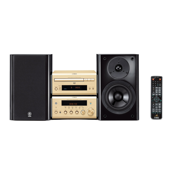
The MCR-E810 is composed of the RX-E810, NX-E800 and DVD-E810.
The MCR-E410 is composed of the RX-E410, NX-E800 and CDX-E410.
This service manual is for the RX-E810, RX-E410 and NX-E800.
For service manual of the DVD-E810 and CDX-E410, please refer to the following publication number:
This manual has been provided for the use of authorized YAMAHA Retailers and their service personnel.
It has been assumed that basic service procedures inherent to the industry, and more specifically YAMAHA Products, are
already known and understood by the users, and have therefore not been restated.
WARNING:
IMPORTANT:
The data provided is believed to be accurate and applicable to the unit(s) indicated on the cover. The research, engineering,
and service departments of YAMAHA are continually striving to improve YAMAHA products. Modifications are, therefore,
inevitable and specifications are subject to change without notice or obligation to retrofit. Should any discrepancy appear to
exist, please contact the distributor's Service Division.
WARNING:
IMPORTANT:
I CONTENTS
To Service Personnel . . . . . . . . . . . . . . . . . . . . 2
System Composition . . . . . . . . . . . . . . . . . . . . . . 3
Front Panels . . . . . . . . . . . . . . . . . . . . . . . . . . . . . 4
Rear Panels . . . . . . . . . . . . . . . . . . . . . . . . . . . . 4–6
Remote Control Panels . . . . . . . . . . . . . . . . . . 6
Specifications . . . . . . . . . . . . . . . . . . . . . . . . . . . . 7
Internal View . . . . . . . . . . . . . . . . . . . . . . . . . . . . . 8
Disassembly Procedures . . . . . . . . . . . . . . . . . 8
Self Diagnosis Function (Diag) . . . . . . . . . 9–15
Amp Adjustments . . . . . . . . . . . . . . . . . . . . . . . . 16
1 0 1 0 1 9
DVD-E810
CDX-E410
IMPORTANT NOTICE
Failure to follow appropriate service and safety procedures when servicing this product may result in per-
sonal injury, destruction of expensive components, and failure of the product to perform as specified. For
these reasons, we advise all YAMAHA product owners that any service required should be performed by
an authorized YAMAHA Retailer or the appointed service representative.
The presentation or sale of this manual to any individual or firm does not constitute authorization, certifica-
tion or recognition of any applicable technical capabilities, or establish a principle-agent relationship of
any form.
Static discharges can destroy expensive components. Discharge any static electricity your body may have
accumulated by grounding yourself to the ground buss in the unit (heavy gauge black wires connect to this
buss).
Turn the unit OFF during disassembly and part replacement. Recheck all work before you apply power to
the unit.
2006
This manual is copyrighted by YAMAHA and may not be copied or
redistributed either in print or electronically without permission.
MCR-E810/MCR-E410
SERVICE MANUAL
SERVICE MANUAL
101017
101018
Display Data . . . . . . . . . . . . . . . . . . . . . . . . . . . . . 17
Ic Data . . . . . . . . . . . . . . . . . . . . . . . . . . . . . . . . 18–22
Block Diagrams . . . . . . . . . . . . . . . . . . . . . . 23–24
Printed Circuit Boards . . . . . . . . . . . . . . . 25–31
Pin Connection Diagrams . . . . . . . . . . . . . . . . 32
Schematic Diagrams . . . . . . . . . . . . . . . . . . 33–37
Replacement Parts List . . . . . . . . . . . . . . 39–48
Remote Controls . . . . . . . . . . . . . . . . . . . . . 49–50
System Control . . . . . . . . . . . . . . . . . . . . . . 51–58
All rights reserved.
NX-E800
P.O.Box 1, Hamamatsu, Japan
'06.07

Advertisement

Table of Contents
loading

Summary of Contents for Yamaha MCR-E810

  • Page 1: Micro Component System

    This manual has been provided for the use of authorized YAMAHA Retailers and their service personnel. It has been assumed that basic service procedures inherent to the industry, and more specifically YAMAHA Products, are already known and understood by the users, and have therefore not been restated.
  • Page 2: To Service Personnel

    RX-E810/RX-E410/NX-E800 I TO SERVICE PERSONNEL AC LEAKAGE WALL EQUIPMENT TESTER OR OUTLET UNDER TEST EQUIVALENT 1. Critical Components Information Components having special characteristics are marked s and must be replaced with parts having specifications equal to those originally installed. 2. Leakage Current Measurement (For 120V Models Only) When service has been completed, it is imperative to verify INSULATING that all exposed conductive surfaces are properly insulated...
  • Page 3: System Composition

    RX-E810/RX-E410/NX-E800 I SYSTEM COMPOSITION The MCR-E810 consists of the DVD-E810, RX-E810 and NX-E800. The MCR-E410 consists of the CDX-E410, RX-E410 and NX-E800. MCR-E810 (U, C, T, K, A, B, G, L, V models) MCR-E410 (B, G models) DVD-E810 CDX-E410 RX-E810...
  • Page 4: Front Panels

    RX-E810/RX-E410/NX-E800 I FRONT PANELS I REAR PANELS RX-E810 (U, C, T, K, A, B, G, L, V models) RX-E810 (U, C models) RX-E410 (B, G models) RX-E810 (T model) NX-E800 (U, C, T, K, A, B, G, L, V models) RX-E810 (K model) RX-E810 (A model)
  • Page 5 RX-E810/RX-E410/NX-E800 RX-E810 (B model) RX-E410 (B model) RX-E810 (G model) RX-E410 (G model) RX-E810 (L model) RX-E810 (V model)
  • Page 6: Remote Control Panels

    RX-E810/RX-E410/NX-E800 NX-E800 I REMOTE CONTROL PANELS RX-E810 RX-E810 RX-E410 (U, C, T, K, A, L, V models) (B, G models) (B, G models)
  • Page 7: Specifications

    RX-E810/RX-E410/NX-E800 I SPECIFICATIONS I AUDIO SECTION • DIMENSIONS Minimum RMS Output Power (Power Amp. section) Channel Separation Finish 20 Hz to 20 kHz, 0.1 % THD, 6 ohms ....40 W + 40 W [RX-E810] [RX-E810] 1 kHz, 0.1 % THD, 6 ohms ....... 55 W + 55 W DVD, etc., Input 5.1 k-ohms shorted, 1 kHz / 10 kHz Gold color ............
  • Page 8: Internal View

    RX-E810/RX-E410/NX-E800 I INTERNAL VIEW • When checking the P.C.B.: a. Remove the top cover and the front panel unit. k. With the rear panel attached, set the MAIN P.C.B. on its b. Remove 2 screws (6). (Fig. 3) side. c. Remove the OPERATION (2) P.C.B. which is con- At this time, set the power transformer on its side as nected directly to the lower P.C.B.
  • Page 9 RX-E810/RX-E410/NX-E800 I SELF DIAGNOSIS FUNCTION (DIAG) This unit has self diagnosis functions that are intended for inspection, measurement and location of faulty point. There are 9 DIAG menu items, each of which has sub-menu items. Listed in the table below are menu items and sub-menu items. MAIN MENU SUB MENU FIRMWARE VERSION...
  • Page 10 RX-E810/RX-E410/NX-E800 • Starting DIAG Press the “STANDBY/ON” key while simultaneously pressing those two keys of the main unit as indicated in the figure below. Keys of main unit Turn on the power while pressing these keys. • Starting DIAG in the protection cancel mode If the protection function works and causes hindrance to trouble diagnosis, cancel the protection function as described below, and it will be possible to enter the DIAG mode.
  • Page 11 RX-E810/RX-E410/NX-E800 When there is a history of protection function: The FL display appears as shown below depending on the type of the protection function. The protection function worked due to a defect or overload in the power supply. If the power P1 PRT:000 A is turned on with the abnormality unsolved, the protection function works in about 3 sec- onds to turn off the power.
  • Page 12 RX-E810/RX-E410/NX-E800 1. FIRMWARE VERSION The firmware version, model, destination and checksum are displayed. The checksum is obtained by adding the data at every 16 bits for each program area and expressing the result as a 4-figure hexadecimal data. * Numeric values in the figure example are for reference. Firmware version of microprocessor VER.xxx 8 UC Description (UC, BG, ATK, LV)
  • Page 13 RX-E810/RX-E410/NX-E800 3. FACTORY PRESET This menu is used to reserve/inhibit initialization of the backup RAM (Set menu contents, etc. of the sound field program). PRESET INHIBIT (Initialization inhibited) 3.PRESET INHI RAM initialization is not executed. Select this sub-menu to protect the values set by the user. Note: The protection history will not be erased using PRESET INHIBIT.
  • Page 14 RX-E810/RX-E410/NX-E800 5. iPod SYSTEM STATUS The voltage value of pin No. 92 of IC200 is displayed, us- DOCK loop back check ing 5V/500 as standard. After turning off the power, short between pins No. 14 (TX) and No. 18 (RX). (Make sure that the power is turned off when shorting SI:xxx [y]:OK pins.)
  • Page 15 RX-E810/RX-E410/NX-E800 6. PROTECTION HISTORY 9. TURN OFF THE POWER FACTOR HISTORY Four protection histories are displayed. Up to 5 past factors which caused the power to turn OFF are displayed. When the “MEMORY” key is pressed during display, the 6-1 No PRT history of the power OFF causal factors are initialized.
  • Page 16 RX-E810/RX-E410/NX-E800 I AMP ADJUSTMENTS Confirmation of Idling Current 1) No signal applied. 2) Non-loaded condition. 3) Aging is not necessary. Item Test Point Rating (DC) Note If the measured voltage exceeds 2.6mV, cut the lead wire of R80 (L ch) MAIN L (Between terminal) or R81 (R ch) and then check again if each measured value satisfies the...
  • Page 17: Display Data

    RX-E810/RX-E410/NX-E800 I DISPLAY DATA G V501 : 16-BT-133GNK (VH034300) PATTERN AREA G PIN CONNECTION Pin No. Connection Pin No. Connection Note : 1) F1, F2 ..Filament 2) NP ..No pin 3) NX ..No extened Pin 4) 1G ~ 16G ..Grid 5) NC ..
  • Page 18 RX-E810/RX-E410/NX-E800 I IC DATA IC200 : M30620MCP-A41FP (INPUT P.C.B.) Microprocessor P4_4/CS0 P0_7/AN0_7/D7 P0_6/AN0_6/D6 P4_5/CS1 P4_6/CS2 P0_5/AN0_5/D5 P0_4/AN0_4/D4 P4_7/CS3 P0_3/AN0_3/D3 P5_0/WRL/WR P0_2/AN0_2/D2 P5_1/WRH/BHE P0_1/AN0_1/D1 P5_2/RD P0_0/AN0_0/D0 P5_3/BCLK P10_7/AN7/KI3 P5_4/HLDA P10_6/AN6/KI2 P5_5/HOLD P10_5/AN5/KI1 P5_6/ALE P10_4/AN4/KI0 P5_7/RDY/CLKOUT P10_3/AN3 P6_0/CTS0/RTS0 P10_2/AN2 P6_1/CLK0 P10_1/AN1 P6_2/RXD0/SCL0 AVSS P6_3/TXD0/SDA0 P10_0/AN0...
  • Page 19 RX-E810/RX-E410/NX-E800 IC200 : M30620MCP-A41FP (INPUT P.C.B.) Microprocessor Pin No. Port Name Function P96/ANEX1/SOUT4 SADEV_DI Serial data output P95/ANEX0/CLK4 SADEV_DO Serial data input P94/DA1/TB4in SADEV_CK Serial clock output P93/DA0/TB3in TU_STAT TUNED detect P92/TB2in/SOUT3 TU_ST/MON STEREO detect P91/TB1in/SIN3 TU_MUTE TUNER MUTE output P90/TB0in/CLK3 BYTE BYTE...
  • Page 20 RX-E810/RX-E410/NX-E800 IC200 : M30620MCP-A41FP (INPUT P.C.B.) Microprocessor Pin No. Port Name Function P30/A8 Ground for microprocessor P27/A7 P26/A6 P25/A5 P24/A4 PD_LED PURE DIRECT LED output P23/A3 P_RLY Power relay output P22/A2 SYS_I Protection inhibit/Permit identify input L = Permitted / H = Inhibited P21/A1 SYS_O System communication output...
  • Page 21 RX-E810/RX-E410/NX-E800 IC501 : M66003-0131FP (OPERATION P.C.B.) FL display driver DIG15/SEG38 DIG16/SEG37 DIG17/SEG36 SEG35 SEG00 SEG01 SEG02 SEG03 SEG04 SEG05 SEG06 SEG07 SEG08 SEG09 SEG10 SEG11 17 18 19 20 21 22 23 24 25 26 27 28 29 Display code CGROM SEG00 (35 bit x 166)
  • Page 22 RX-E810/RX-E410/NX-E800 IC501 : M66003-0131FP (OPERATION P.C.B.) FL display driver Pin No. Symbol Name Function RESET RESET Reset input When “L”, M66003 is initialized. CEFD Chip select input When “L”, communication with the MCU is possible. CKFD Shift clock input When “H”, any instruction from the MCU is neglected. SDATA DTFD Serial data input...
  • Page 23 RX-E810/RX-E410/NX-E800 I BLOCK DIAGRAMS AUDIO SECTION BLOCK DIAGRAM To DVD/CD OPERATION (1) • See page 33 → INPUT (1) SCHEMATIC DIAGRAM • See page 37 → XL200 SCHEMATIC DIAGRAM 32.7kHz Timer LED D501 IP_TXD IP_RXD IR Remote U501 IP_DET DOCK for iPod Power Supply Detection 82, 83 Input Selector...
  • Page 24 RX-E810/RX-E410/NX-E800 POWER SECTION BLOCK DIAGRAM • See page 35 MAIN (1) → SCHEMATIC DIAGRAM Power Transformer OPERATION (2) • See page 34 → SCHEMATIC DIAGRAM Q701 +3.3V 3.3V F1 (U, C, G models) / J1 (T, K, A, B, L, V models) MAIN (3) •...
  • Page 25 RX-E810/RX-E410/NX-E800 I PRINTED CIRCUIT BOARDS INPUT (2) (CB201) OPERATION (1) P.C.B. (Side A) PRESET/TUNING PRESET/BAND AUTO/MAN'L MEMORY DISPLAY P-RLY CGND REMOTE CGND +5CPU KEY0 KEY1 ROT_A HOUR TIMER TIME ADJ PHONES ROT_B FL_CK FL_DT /FL_CE /FL_IC TIMER_LED HP_DET /STANDBY /TIMER PD_LED INPUT (1) INPUT...
  • Page 26 RX-E810/RX-E410/NX-E800 OPERATION (2) P.C.B. (Side A) OPERATION (2) P.C.B. (Side B) IP_L IP_R +12V -12V IGND IP_RX IP_PWR IP_DET IP_TX +5CPU CGND INPUT (1) (CB206) DOCK • Semiconductor Location Ref no. Location D705 IC703 IC704 IC707 Q701...
  • Page 27 RX-E810/RX-E410/NX-E800 Circuit No. U, C T, K, A, B, G C76, C79, C125, C126 C81, C82 MAIN (1) P.C.B. C116 MAIN (2) (CB1) R142, R143, R813, R184 (Side A) TO DVD-E810 X : NOT USED (RX-E810 model) O : USED/APPLICABLE TO CDX-E410 (RX-E410 model) SUBWOOFER...
  • Page 28 RX-E810/RX-E410/NX-E800 MAIN (2) P.C.B. MAIN (3) P.C.B. MAIN (4) P.C.B. (Side A) (Side A) (Side A) U, C, T, A, B, G, L, V models INPUT (1) INPUT (1) (CB209) (W201) INPUT (1) (CB205) MAIN (1) (CB14) /RESET OPERATION (1) P_DET CGND SGND...
  • Page 29 RX-E810/RX-E410/NX-E800 MAIN (2) P.C.B. MAIN (4) P.C.B. (Side B) (Side B) • Semiconductor Location Ref no. Location IC10 IC11...
  • Page 30 RX-E810/RX-E410/NX-E800 TUNER MAIN (2) (W1) OPERATION (2) B, G models (CB702) INPUT (1) P.C.B. (Side A) PD_LED /TIMER /STANDBY HP_DET TIMER_LED /FL_IC /FL_CE FL_DT FL_CK ROT_B ROT_A KEY1 DVD/CD KEY0 +5CPU CGND REMOTE CGND P_RLY OPERATION (1) (CB501) MD/TAPE MVOL_DW MVOL_UP P-DIRECT MGND...
  • Page 31 RX-E810/RX-E410/NX-E800 INPUT (2) P.C.B. (Side B) INPUT (2) P.C.B. (Side A) Power Transformer • Semiconductor Location Ref no. Location SGND D200 D201 PROT_1 +12_M D205 +12V D206 DGND D207 Q200 SGND Q201 Q202 Q203 MAIN (1) (CB13) OPERATION (1) (W501)
  • Page 32 RX-E810/RX-E410/NX-E800 I PIN CONNECTION DIAGRAMS • ICs • Diodes BA50BC0T KIA7805API LB1641 LC72722PM LC78211 1SS133 1SS355 S1NB20 1A 200V S1NB60 1.0A 600V 1SS176 1SS380 1SS270A MA8030-L 2.9V 1SR139-400 MA8036-H 3.7V MTZJ5.1B 5.1V MA8039-H 4.0V MTZJ5.1C 5.1V MA8051-M 5.1V MTZJ12C 12V MA8056-M 5.6V Anode MTZJ22C 22V...
  • Page 33 RX-E810/RX-E410/NX-E800 SCHEMATIC DIAGRAM OPERATION 1/2 OPERATION (1) FL DISPLAY Page 37 to INPUT (2)_CB201 -22.3 -22.3 -22.3 -15.7 -15.9 -14.3 -14.3 -20.7 -20.7 -19.1 -22.3 -15.8 -15.8 -20.7 FL DRIVER -15.8 -15.8 -15.8 -17.5 -19.1 -15.9 -14.3 -15.9 -22.5 -22.3 -20.7 -20.7 -20.5...
  • Page 34 RX-E810/RX-E410/NX-E800 OPERATION 2/2 11.2 Page 37 to INPUT (1)_CB206 -11.1 OPERATION (2) IC703: SN74LV32ANSR IC704: MM74HCT08SJX IC707: NJM2068MD-TE2 Quadruple 2-Input positive-OR gates Quadruple 2-Input AND gate Dual operational amplifier –IN – – –IN –V # All voltages are measured with a 10MΩ/V DC electronic volt meter. # Components having special characteristics are marked s and must be replaced with parts having specifications equal to those originally installed.
  • Page 35 RX-E810/RX-E410/NX-E800 MAIN 1/2 Page 36 Page 37 Page 37 Page 36 Page 37 to MAIN (4)_CB21 to INPUT (1)_CB202 to INPUT (2)_W200 to MAIN (2)_CB1 to INPUT (1)_CB207 10.2 AC 8.6 10.2 POWER TRANSFORMER 29.5 17.2 38.7 IC7: LM61CIZ -23.1 Temperature sensor -38.6 -23.1...
  • Page 36 RX-E810/RX-E410/NX-E800 MAIN 2/2 IC1, 2: TLP421 IC4, 5, 10, 11: NJM2068MD-TE2 Photo transistor Dual operational amplifier Page 37 to INPUT (1)_CB205 Anode Collector MAIN (3) –IN – – –IN Cathode Emitter –V IC3: TC4013BP Dual D-type flip flop (2.8) RESET1 SET1 DATA1 (2.8)
  • Page 37 RX-E810/RX-E410/NX-E800 INPUT Page 36 Page 34 TUNER to MAIN (2)_W1 to OPERATION (2)_CB702 IC203: LC72722PM RDS signal processor VDDA CLOCK VDDD RECOVERY REFERENCE (57 kHz) (1187.5 Hz) VOLTAGE VSSA VSSD VREF 57 kHz ANTIALIASING SMOOTHING DATA MPX IN RDS-ID DECODER FILTER FILTER (SCF)
  • Page 38: Replacement Parts List

    RX-E810/RX-E410/NX-E800 I REPLACEMENT PARTS LIST • ELECTRICAL COMPONENT PARTS WARNING G Components having special characteristics are marked s and must be replaced with parts having specifications equal to those originally installed. ABBREVIATIONS IN THIS LIST ARE AS FOLLOWS: C.A.EL.CHP : CHIP ALUMI.ELECTROLYTIC CAP L.EMIT : LIGHT EMITTING MODULE C.CE...
  • Page 39 RX-E810/RX-E410/NX-E800 P.C.B. OPERATION Ref. No. Part No. Description Markets Ref. No. Part No. Description Markets WH453900 P.C.B. OPERATION UCKBGLV IC703 X4176A00 IC SN74LV32ANSR OR CB501 VU281800 CN 18P SE IC704 XZ013A00 IC MM74HCT08SJX 2-IN CB502 VU281500 CN 15P SE 9604S IC707 X3505A00 IC NJM2068MD-TE2...
  • Page 40 RX-E810/RX-E410/NX-E800 P.C.B. MAIN Ref. No. Part No. Description Markets Ref. No. Part No. Description Markets WH452600 P.C.B. MAIN C46-47 WE100200 C.PP 22pF 630V WH452700 P.C.B. MAIN UR237100 C.EL 10uF WH452800 P.C.B. MAIN US062100 C.CE.CHP 100pF 50V B WH452900 P.C.B. MAIN UT952220 C.PP 220pF 100V...
  • Page 41 RX-E810/RX-E410/NX-E800 P.C.B. MAIN and P.C.B. INPUT Ref. No. Part No. Description Markets Ref. No. Part No. Description Markets VU995400 DIODE.ZENR MA8100-M 10V s R44 HV753220 R.CAR.FP 2.2Ω 1/4W VT332900 DIODE 1SS355 WB633000 R.MTL.OXD 1KΩ 1/2W J s D11 V4756800 DIODE S1NB60 1.0A 600V WB633000 R.MTL.OXD 1KΩ...
  • Page 42 RX-E810/RX-E410/NX-E800 P.C.B. INPUT Ref. No. Part No. Description Markets Ref. No. Part No. Description Markets C202 US062100 C.CE.CHP 100pF 50V B D213 VU993000 DIODE.ZENR MA8056-M 5.6V C203 US135100 C.CE.CHP 0.1uF IC200 X8212A00 IC CPU M30620MCP-A41FP (MASK ROM) C204-206 US062100 C.CE.CHP 100pF 50V B IC201 X3505A00 IC...
  • Page 43 RX-E810/RX-E410/NX-E800 Chip Resistors The chip resistor is not supplied as a replacement part. * When a chip resistor is necessary, use the following part. AAX60720: CHIP RESISTOR SAMPLE BOOK Ref. No. Part No. Description Markets Ref. No. Part No. Description Markets R.CHP 0Ω...
  • Page 44 RX-E810/RX-E410/NX-E800 Carbon Resistors Value 1/4W Type Part No. 1/6W Type Part No. Value 1/4W Type Part No. 1/6W Type Part No. 1.0 Ω 3100 3100 10 kΩ 7100 7100 HJ35 HF85 HF45 HF45 1.8 Ω ❊ 3180 11 kΩ 7110 7110 HJ35 HF45...
  • Page 45 RX-E810/RX-E410/NX-E800 • RX-E810/RX-E410 OVERALL ASS’Y 2-103 B, G models 2-112 RX-E810 5 (2) 2-106 200-1 RX-E410 2-112 201-1 2-105 U, C, T, L, V models 1-115 1-116 1-103 LEFT 2-107 2-111 K, A, B, G models 2-110 2-102 2-107 2-111 1-11 1-104 5 (1)
  • Page 46 RX-E810/RX-E410/NX-E800 Ref. No. Part No. Description Remarks Markets Ref. No. Part No. Description Remarks Markets WH453900 P.C.B. ASS'Y OPERATION UCKBGLV MF113100 FLEXIBLE FLAT CABLE 13P 100mm P=1.25 1-10 MF115140 FLEXIBLE FLAT CABLE 15P 140mm P=1.25 MF107080 FLEXIBLE FLAT CABLE 7P 80mm P=1.25 1-11 MF118180 FLEXIBLE FLAT CABLE...
  • Page 47 RX-E810/RX-E410/NX-E800 • NX-E800 OVERALL ASS’Y Ref. No. Part No. Description Remarks Markets WH629500 CABINET ASS'Y WH245200 CABINET ASS'Y 1-12 CB605250 HOLDER WH629600 FRONT GRILLE ASS'Y WH245300 FRONT GRILLE ASS'Y XW275B00 DRIVER TWEETER 2.5cm 5Ω JA05U3 XW276C00 DRIVER WOOFER 13cm 6Ω JA1360 V9509800 NETWORK ASS'Y...
  • Page 48 RX-E810/RX-E410/NX-E800 I REMOTE CONTROL WH217700: RX-E810 (U, C, T, K, A, L, V models) WH217800: RX-E810 (B, G models) <JP1•JP2> • SCHEMATIC DIAGRAM • KEY CODE Common DVD/CD TUNER ACX/TV DOCK TAPE/MD Label code Function code Function code Function code Function code Function...
  • Page 49 RX-E810/RX-E410/NX-E800 I REMOTE CONTROL WH256400: RX-E410 (B, G models) • SCHEMATIC DIAGRAM • PANEL • KEY LAYOUT • KEY CODE CUSTOM DATA Key Label CODE CODE : Not Mounted STANDBY/ON 9 10 (VOLUME) TUNER BAND TAPE/MD AUX/TV DOCK FOLDER/ (INPUT) DISPLAY (VOLUME) (INPUT)
  • Page 50: System Control

    RX-E810/RX-E410/NX-E800 I SYSTEM CONTROL 1. External Bus 1.1. Physical format of external bus It is composed of 2 bus lines. MCR-E810 MCR-E410 RX command line RX command line RX unit DVD unit RX unit CD unit (RX-E810) (DVD-E810) (RX-E410) (CDX-E410) State info.
  • Page 51 RX-E810/RX-E410/NX-E800 Example: Process Eject Initialize Power on Loading Stop Seek Play Pause Play Skip Play Search Play H x 2/3 H x 1/3 Reset start "STANDBY/ON" "EJECT" Load "PLAY" "PAUSE" "PLAY" "SKIP" "SEARCH" "PLAY" Process Play Stop Seek Play Eject Loading Stop Seek Play...
  • Page 52 RX-E810/RX-E410/NX-E800 2. Command and Operation Key Code The system command and the system remote control code described as follows are transmitted through RX command bus. 2.1 RX request command Name Code Function to DVD to CD POWER_ON 7C-F6 78-7E Power on request POWER_OFF 7C-F7 78-7F...
  • Page 53 RX-E810/RX-E410/NX-E800 3. Command Communication for System Function 3.1 Power on (1) Power on by RX “STANDBY/ON” key operation RX turns on the power by RX’s “STANDBY/ON” key and at the same time DVD/CD also turns on the power if DVD/CD state is power on at the last RX’s power on. RX unit DVD/CD unit [Power shut down]...
  • Page 54 RX-E810/RX-E410/NX-E800 3.2 Timer function The unit setted in this RX timer function is playbacked at the setting time as the ON-TIME. It functions even when at setted time the system is already in power on state or the unit is already playbacked. (1) Timer play The state is not changed if the setted unit is already in the state of playback.
  • Page 55 RX-E810/RX-E410/NX-E800 3.3 Standby (power off) (1) System standby The power supply through AC outlet of RX is shut down in system standby (power off). The microcomputer of the unit connected with AC outlet of RX cannot work after system power off. When there is processing that should be finished before the system power off, the system is turned power off after such processing completion.
  • Page 56 RX-E810/RX-E410/NX-E800 (3) Auto standby (power off) When 30 minutes pass with the following conditions consisted, the system turns off the power (standby) automatically. a. The unit connected with an external bus is in the standby state. b. RX input function is DVD/CD. c.
  • Page 57 RX-E810/RX-E410/NX-E800 3.4 Display control (1) Display dimmer function This is the function to change the brightness of DVD/CD’s display by operating RX. RX unit DVD/CD unit Display dimmer on operation DIMMER_ON command Display dimmer on Display dimmer on Display dimmer off operation DIMMER_OFF command Display dimmer off Display dimmer off...

This manual is also suitable for:

Rx-e410Mcr-e410Nx-e800Rx-e810

Table of Contents