Sign In
Upload
Download
Table of Contents
Contents
Add to my manuals
Delete from my manuals
Share
URL of this page:
HTML Link:
Bookmark this page
Add
Manual will be automatically added to "My Manuals"
Print this page
×
Bookmark added
×
Added to my manuals
Manuals
Brands
Jedia Manuals
Amplifier
JPA-1060
Operating instruction
Jedia JPA-1060 Operating Instruction
Jtp-10 fm / am tuner; jcp-10 cassette deck; jcr-10 cassette receiver
Hide thumbs
1
2
3
4
5
6
7
8
9
10
11
12
13
14
15
16
Table Of Contents
17
page
of
17
Go
/
17
Contents
Table of Contents
Bookmarks
Table of Contents
F Ront Panel Controls
Power Switch
Master Volume
Siren Switch
Tuner Display
Impedance Selector Switch
Mute Control
Am Outdoor Antenna
Amplifier Section
Tuner Section
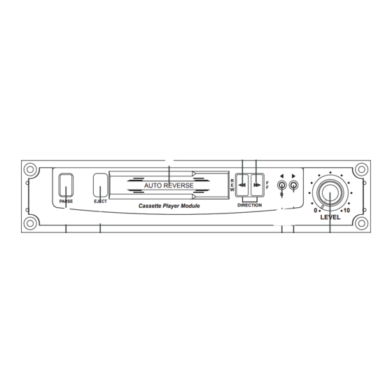
Cassette Deck Section
Advertisement
Quick Links
1
F Ront Panel Controls
2
Power Switch
3
Master Volume
4
Impedance Selector Switch
5
Amplifier Section
Download this manual
PUBLIC ADDRESS
AMPLIFIER
JPA-1060
JPA-1120
FM / AM TUNER
JTP-10
CASSETTE DECK
JCP-10
CASSETTE RECEIVER
JCR-10
WWW.JEDIA.COM
Table of
Contents
Previous
Page
Next
Page
1
2
3
4
5
Advertisement
Table of Contents
Need help?
Do you have a question about the JPA-1060 and is the answer not in the manual?
Ask a question
Questions and answers
Related Manuals for Jedia JPA-1060
Amplifier Jedia JPA-1120 Operating Instruction
Jtp-10 fm / am tuner; jcp-10 cassette deck; jcr-10 cassette receiver (17 pages)
Amplifier Jedia MMA-400 Series Operating Instructions Manual
Module mixer pre amplifier (29 pages)
Amplifier Jedia JPA-1120EM Operating Instructions Manual
Emergency portable amplifier (16 pages)
Amplifier Jedia JPA-1120B Operating Instructions Manual
Att. zone amplifier (20 pages)
Amplifier Jedia JPA-1120B Operating Instructions Manual
(20 pages)
Amplifier Jedia JPA-060CP Manual
1 channel p.a power amplifier (12 pages)
Amplifier Jedia JPA-480CP Manual
1 channel p.a power amplifier (12 pages)
Amplifier Jedia JMA-300A Operating Instruction
(12 pages)
Amplifier Jedia JWP-500 Operating Instructions Manual
(8 pages)
Amplifier Jedia JMA-1410 Operating Instructions Manual
(10 pages)
Amplifier Jedia JMA-2104 Operating Instructions Manual
4-bus preamplifier (10 pages)
Amplifier Jedia JME-2A Operating Instructions Manual
2/4-module extension (11 pages)
Amplifier Jedia JDA-250 Operating Instructions Manual
(12 pages)
Amplifier Jedia JFX-425 Operating Instructions Manual
4 channel power amplifier professional (11 pages)
Amplifier Jedia JDB-250 Operating Instructions Manual
(12 pages)
Amplifier Jedia L3.0 Operating Instructions Manual
Professional stereo power amplifier (15 pages)
This manual is also suitable for:
Jpa-1120
Table of Contents
Save PDF
Print
Rename the bookmark
Delete bookmark?
Delete from my manuals?
Login
Sign In
OR
Sign in with Facebook
Sign in with Google
Upload manual
Upload from disk
Upload from URL


Need help?
Do you have a question about the JPA-1060 and is the answer not in the manual?
Questions and answers