
Related Manuals for Jedia JPA-480CP


Summarization of Contents
Safety and General Information
Caution Avis
General warnings about electrical shock and exposure to elements.
Safety Instructions
Essential safety guidelines for operating the JPA-Series amplifiers.
Features
Key features and functionalities of the JPA-Series amplifiers.
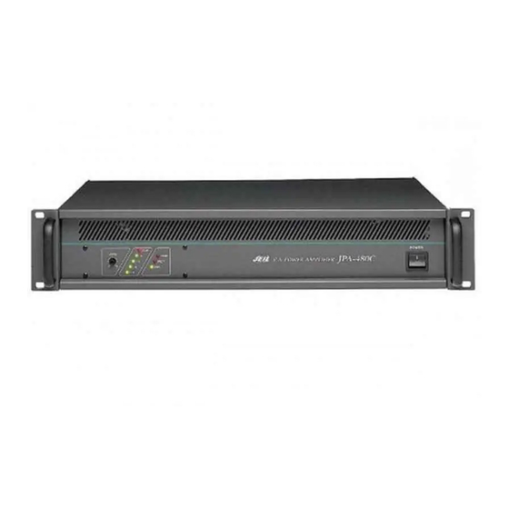
Front Panel Controls
Power Switch
Operation of the main power switch for supplying AC power.
LED Indicators
Explanation of various LED indicators for status and protection.
Output Level Meter
How to use the LED level meter for volume adjustment.
PGM Level Volume
Control for adjusting the amplifier's output volume level.
Rear Panel Controls and Connectivity
Program Audio Input Terminal
Terminal for connecting the PROGRAM audio signal for normal announcements.
Priority Audio Input Terminals
Terminals for PRIORITY audio signals like E/M or remote announcements.
Priority Level Volumes
Volume control for adjusting PRIORITY audio input signal levels.
Priority Control Input Terminal
Terminals for controlling PRIORITY functions via external signals.
Terminal for Switch Contact Point
Connection point for external switches or relay contacts to control PRIORITY.
Connection for JRG-220A
Specific connection instructions for the JRG-220A unit.
Rear Panel Terminals and Power
Monitor Terminal
Terminal for monitoring amplifier output volume and sound level.
Speaker Output Terminals
Terminals for connecting speakers with various impedance matching options.
DC Power Terminal
Input terminal for DC 24V power supply, used for emergency backup.
AC Power Inlet
Socket for connecting the main AC power cord.
Power Output Expansion
Series Connection Method
Guide on connecting amplifiers in series to increase total power output.
Impedance Calculation for Series Connection
Method for calculating primary impedance matching for series connections.
Series Connection Specifications
Output voltage and impedance details for series connections of different models.
Conditions for Series Connection
Scenarios where series connection is recommended for higher power needs.
Technical Specifications
Input Sensitivity and Impedance
Specifies input sensitivity and impedance for PGM and PRIORITY signals.
Rated Output
Lists the rated RMS output power for each amplifier model.
Output Impedance
Details the output impedance options available for different voltage and impedance settings.
Frequency Response
Specifies the audio frequency range the amplifier covers.
Signal to Noise Ratio
Indicates the amplifier's noise floor relative to the signal level.
THD
Total Harmonic Distortion levels for different amplifier models.
Input Filter (H.P.F)
Details the High Pass Filter characteristics for reducing low-frequency resonance.
Power Consumption
Lists the power consumption figures for each amplifier model.
Current Draw
Current draw specifications at different power levels and voltages.
General Specifications
Power
Specifies the AC and DC power input requirements for the amplifiers.
Dimensions
Provides the physical dimensions of the amplifiers in millimeters and inches.
Weight
Lists the weight of each amplifier model in kilograms and pounds.
System Connections
Connection Diagrams
Illustrates various system configurations and component interconnections.
Block Diagram
Functional Overview
Diagram showing the internal signal flow and components of the amplifier.
Need help?
Do you have a question about the JPA-480CP and is the answer not in the manual?
Questions and answers