Numatic TTV 678 Owner's Instructions Manual
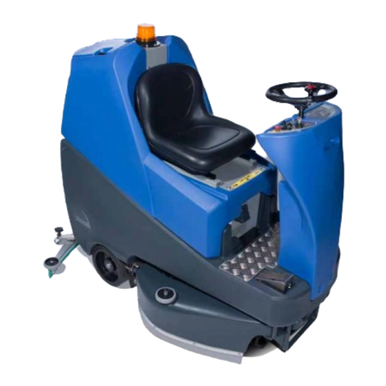
Ride-on scrubber dryer
Hide thumbs
Also See for TTV 678:
- Owner's instructions manual (68 pages) ,
- Owner's instructions manual (68 pages)

Subscribe to Our Youtube Channel
Related Manuals for Numatic TTV 678


Summary of Contents for Numatic TTV 678
- Page 1 Owner Instructions Original instructions Warning! Read instructions before using the machine TTV 678 Ride-on Scrubber Dryer TTV 678 www.numatic.com...
-
Page 2: Table Of Contents
Before continuing, please refer to Quick Set Up Guide on Page 8 Index Page 2 Machine Overview Page 3 Control Panel Overview Page 4 Rating Label / Personal Protective Equipment / Recycling Page 5 Safety Precautions Page 6 / 7 Page 8 Quick Set-up Guide Machine set-up... - Page 3 Machine Overview 13 15 19 20 21 Operator Control Panel (see page 4) Gel batteries Brush load-adjuster knob Chemical dosing tank ( 5 litre ) Brush deck release lever Charger Brush deck foot pedal Accelerator pedal Clean-water tank fill point Clean-water Tank Emptying Hose &...
-
Page 4: Control Panel Overview
Control Panel Overview Battery Charge Level Meter Waste-water ‘Full’ Indicator Brush Operation / Load Indicator Off Aisle Vacuum Button Clean Speed Button Main control On / Off key 4 / 5 / 6 Operator Pre-set Buttons Emergency Stop Water Flow Indicator Forward / Reverse Switch Brush Speed Indicator Horn Button... - Page 5 3 core Motor Wheel & modified brake lead assembly (321450) PG Controller (208169) Battery Charger: 98A/H Stud Terminal Gel Type Battery In the event of a breakdown contact your Numatic dealer or the Numatic Technical help line +44 (0)1460 269268...
- Page 6 • Regularly examine the charger lead for damage, such as cracking or ageing. If damage is found, replace the lead before further use. • Only replace the charger lead with the correct Numatic approved replacement parts. • Ensure that the work area is clear of obstructions and / or people.
- Page 7 Operators shall be adequately instructed as to the correct use of the machine. If this product does not have a factory installed Numatic battery charger, then it is the responsibility of the owner and user of the product to ensure that the charging system and battery combination are compatible, fit for purpose and safe to use.
-
Page 8: Quick Set-Up Guide
Quick Set-Up Guide PLEASE READ BEFORE COMMENCING ANY OPERATION. AFTER THE REMOVAL OF ALL THE PACKAGING, CAREFULLY OPEN AND CHECK THE CONTENTS OF THE START UP PACK FIG.1. Contents: 1 x Operator Manual 2 x Battery charging lead 2 x Keys 4 x 40 amp fuses (1 x spare) 2 x Side pod skirts 1 x Brake disengage key... -
Page 9: Fitting The Floor-Tool
Machine Set-up ALWAYS ENSURE THAT THE MACHINE IS SWITCHED OFF BEFORE MAKING ANY ADJUSTMENTS To fit the side pod skirts, first remove the steel retaining strip already fitted to the pod (Fig.7). Align the steel retaining strip within the locating grooves of the rubber skirt and refit using existing screws (Fig.8) Periodically the side skirts should be examined and checked for wear and damage. - Page 10 Machine Set-up Fitting the Hose Guide The vacuum hose has a U-bend clip which creates a U-bend in the hose preventing water spillage when the vacuum is switched off. If you need to remove the U-bend clip for any reason always ensure it is refitted correctly before you resume operation.
-
Page 11: Fitting The Brushes
(see setting the width) (Fig.16). Safety gloves are recommended for the changing of used brushes. Owning the TTV 678 ride-on scrubber dryer is like having 3 machines in one. With three width-settings the operator can quickly adapt the machine to any cleaning situation;... -
Page 12: Setting The Width
850mm Filling the Clean-water Tank The TTV 678 is equipped with a large capacity 120 litre clean-water tank allowing, for large areas to be covered in a single fill. To fill the clean-water tank, lift the cover flap (Fig.19) to expose the filler cap. -
Page 13: Chemical Dosing System
Do not operate machine unless the Operator Manual has been read and fully understood. The TTV 678 ride-on scrubber dryer has an optional automatic chemical-dosing system. Simply fill the 5 litre chemical dosing bottle and the machine will deliver the correct mix ratio as set by the operator, depending on the floor and cleaning conditions. -
Page 14: Lowering The Floor-Tool
Machine Set-Up Lowering the Brush Deck After preparing the floor (see previous section), we are now ready to set the controls to suit the cleaning conditions. Before any settings can be applied, ensure the brush deck is lowered. While depressing left-hand foot pedal (see Fig.26), press down the release lever (see Fig.27) and gently release the foot pedal to lower the brush deck (see Fig.28). -
Page 15: Adjusting The Seat
Machine Operation Adjusting the Seat Sitting in the driving position, adjust the seat forwards or backwards as necessary by using the lever found on the left-hand side (see Fig.30). Note: The seat is fitted with a pressure sensor that disables the machine until an operator is seated. Setting the Cleaning Controls Insert key into main control (on / off) and turn quarter-turn clockwise to position (1) ‘ON’. -
Page 16: Setting The Operator Pre-Set Buttons
Machine Operation Setting the Operator Pre-set Buttons Settings can be stored using one of the three pre-set store buttons (S1 / S2 / S3). Once settings are entered (chemical dose, brush speed and water-flow), press and hold one of the three pre-set store buttons, a light will flash then remain constant; your settings are now saved. -
Page 17: Emergency Stop Button And Horn
Machine Operation Emergency Stop Button and Horn The TTV 678 is equipped with an electronic braking system. Simply lift your foot from the accelerator and the machine will stop. In an emergency, strike the emergency-stop isolator button The machine will be disabled. - Page 18 Machine Cleaning ALWAYS ENSURE THAT THE MACHINE IS SWITCHED OFF PRIOR TO ANY MAINTENANCE. After use, empty waste-water tank using emptying hose and flush-out with clean-water. Next remove floor-tool vacuum hose and flush out with clean-water. Next empty clean-water tank, using emptying hose and again flush out with clean-water.
- Page 19 PRIOR TO ANY MAINTENANCE The Floor Tool The TTV 678 is provided with the aluminium floor-tool shown. To clean the floor-tool, remove securing-pin and disconnect the lifting strap and remove the floor-tool securing pin pull-free the floor-tool from the rear of the machine.
-
Page 20: Machine Charging
Machine Charging ALWAYS ENSURE THAT THE MACHINE IS SWITCHED OFF PRIOR TO CHARGING. The battery meter displays the charge level of the batteries; when fully charged, all meter lights are illuminated (see Fig.38). As the machine is used and the batteries are discharged, the meter lights will go out from right to left. -
Page 21: Battery Care
Battery Care To ensure your machine remains at its maximum efficiency and prolong your battery life, please follow the simple steps below: Under normal daily usage: Recharge batteries after each use regardless of machine operation time (see page 20). Recharge the machine fully after its last use. Do not leave the machine in a discharged state. Signal (LED) Meaning Yellow... - Page 22 NEVER DISENGAGE THE BRAKE WHEN THE MACHINE IS ON A SLOPE / GRADIENT. NEVER TOW THE MACHINE WITH THE BRAKE ENGAGED. The TTV 678 is equipped with a free-wheel function that will enable the operator to move / tow the machine.
- Page 23 The machine will need to be reset by simply turning the ignition key off and on again. Off-Aisle Accessory Kit (Optional) (606182) In the event of a breakdown contact your Numatic dealer or the Numatic Technical helpline +44 (0)1460 269268 (See back page for company addresses or dealers stamp)
- Page 24 Contact Service Agent.
- Page 25 Contact Service Agent.
- Page 26 Machine will not operate in reverse Floor-tool in lowered position Raise floor-tool (page 14) ‘Causes Battery Indicator to Flash’ In the event of a breakdown contact your Numatic dealer or the Numatic Technical helpline +44 (0)1460 269268 (See back page for company addresses or dealers stamp)
- Page 27 Spare Parts & Accessories BRUSHES: GENERAL PARTS: 606174 330mm Octo Polyscrub Brush 206953 Detent Pin 606172 330mm Octo Nyloscrub Brush 208167 Spare Set of Keys (2 Keys) 606176 330mm Octo Longlife Brush 208165 Bulb 606407 330mm Padloc Octo Drive Board 280001 Seat Cover SQUEEGEE:...
-
Page 28: Schematic Diagrams
TTV 678 - Schematic Diagram Notes ........................................................................................................................................................................................................................ - Page 29 Notes ......................................................................................................................................................................................................................................................................................................................................................................................................
- Page 30 RoHS Directive 2011/65/EU Machine Description: Scrubber Dryer Type: TTV, TRO, CRO series Manufactured by: Numatic International Limited Relevant standards upon which conformity is declared include: IEC 60335-1 2001 + A1 2004 + A2 2006 + National Deviations IEC 60335-2.72 Ed 2.0...
- Page 32 TTV 678 This machine has been packed with the following: Charging Lead Fuses Hose Hook 38 / 32mm Adaptor Signed Distributed by Numatic International Limited Chard, Somerset TA20 2GB ENGLAND. Telephone 01460 68600 Fax: 01460 68458 www.numatic.co.uk Subject to change without prior notice.
Need help?
Do you have a question about the TTV 678 and is the answer not in the manual?
Questions and answers