
Related Manuals for Numatic TTV 678G / 300T


Summary of Contents for Numatic TTV 678G / 300T
- Page 1 TTV 678G / 300T R I D E - O N S C R U B B E R D RY E R Owner Instructions TTV 678G Warning! Read instructions before using the machine...
- Page 2 Free Wheel Function Page 22 Off-aisle Cleaning Function (optional) Page 23 Trouble Shooting / Specifications Page 24 - 26 Recommended Spare Parts Page 27 Schematic Diagrams Page 28 Declaration document Page 30 Warranty Page 31 Company Address Page 32 www.numatic.co.uk...
-
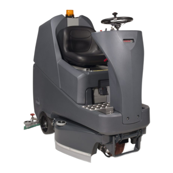
Page 3: Machine Overview
Machine Overview 13 15 19 20 21 Operator Control Panel (see page 4) Gel batteries Brush load-adjuster knob Chemical dosing tank ( 5 litre ) Brush deck release lever Charger Brush deck foot pedal Accelerator pedal Clean-water tank fill point Clean-water Tank Emptying Hose &... -
Page 4: Control Panel Overview
Emergency Stop Button Water Flow Rate Indicator Forward / Reverse Switch Brush Speed Indicator Horn Button Chemical Mix Indicator Charger status light For full easy to follow instructions on control panel set up and use, see machine operation page 15-17. www.numatic.co.uk... -
Page 5: About The Machine
3 core Battery Charger: 120V (50-60Hz) DC Output: 24VDC, 20A Motor Wheel & modified brake lead assembly (904964) In the event of a breakdown contact your Numatic dealer or the Numatic Technical help line +44 (0)1460 269268 T 01460 68600... - Page 6 Operators shall be adequately instructed as to the correct use of the machine. If this product does not have a factory installed Numatic battery charger, then it is the responsibility of the owner and user of the product to ensure that the charging system and battery combination are compatible, fit for purpose and safe to use.
- Page 7 Disconnect hoses from separator and tanks, undo battery terminals and remove batteries. Only use genuine Numatic replacement batteries. Do not allow the batteries to become fully discharged, it may not be possible to recharge them.
- Page 8 (Fig.5). Note: The seat is fitted with a pressure sensor that disables the machine until an operator is seated. When the machine is removed and in a safe position, turn key back to the position (0) ‘OFF’ (Fig.6). www.numatic.co.uk...
-
Page 9: Machine Setup
Machine Set-up ALWAYS ENSURE THAT THE MACHINE IS SWITCHED OFF BEFORE MAKING ANY ADJUSTMENTS To fit the side pod skirts, first remove the steel retaining strip already fitted to the pod (Fig.7). Align the steel retaining strip within the locating grooves of the rubber skirt and refit using existing screws (Fig.8) Periodically the side skirts should be examined and checked for wear and damage. -
Page 10: Fitting The Hose Guide
To re-attach the floor-tool blade to its holder. First loosen the retaining knobs on the floor-tool body and slide onto the holding bracket. Tighten retaining knobs to finger tight. (See Fig.13). www.numatic.co.uk... -
Page 11: Fitting The Brushes
Safety gloves are recommended for the changing of used brushes. Owning the TTV 678G / 300T ride-on scrubber dryer is like having 3 machines in one. With three width-settings the operator can quickly adapt the machine to any cleaning situation;... -
Page 12: Filling The Clean-Water Tank
850mm Filling the Clean-water Tank The TTV 678G / 300T is equipped with a large capacity 120 litre clean-water tank allowing, for large areas to be covered in a single fill. To fill the clean-water tank, lift the cover flap (Fig.19) to expose the filler cap. -
Page 13: Chemical Dosing System
Do not operate machine unless the Operator Manual has been read and fully understood. The TTV 678G / 300T ride-on scrubber dryer has an optional automatic chemical-dosing system. Simply fill the 5 litre chemical dosing bottle and the machine will deliver the correct mix ratio as set by the operator, depending on the floor and cleaning conditions. -
Page 14: Lowering The Brush Deck
Note: If the brush width has not been set, see ‘Setting the width adjustment’ on page 12 before proceeding. Lowering the Floor-tool Lower the floor-tool by moving the release lever to the upper position (Fig.29). Note: The machine will not reverse while the floor-tool is in the lowered position - ‘Causes the battery indicator to flash’. www.numatic.co.uk... -
Page 15: Machine Operation
Machine Operation Adjusting the Seat Sitting in the driving position, adjust the seat forwards or backwards as necessary by using the lever found on the left-hand side (see Fig.30). Note: The seat is fitted with a pressure sensor that disables the machine until an operator is seated. Setting the Cleaning Controls Insert key into main control (on / off) and turn quarter-turn clockwise to position (1) ‘ON’. -
Page 16: Setting The Operator Pre-Set Buttons
Turn it anti-clockwise to decrease load on the brushes and clockwise to increase load / pressure on the brushes (see Fig.31). Note: The run-time of the machine may decrease if the load on the brushes is increased. www.numatic.co.uk... -
Page 17: Emergency Stop Button And Horn
Machine Operation Emergency Stop Button and Horn The TTV 678G / 300T is equipped with an electronic braking system. Simply lift your foot from the accelerator and the machine will stop. In an emergency, strike the emergency-stop isolator button The machine will be disabled. -
Page 18: Machine Cleaning
Lift white plug and remove the filter, rinse and refit. Ensure tank has been emptied and care is taken when working in the vicinity of batteries. NOTE: ANY SPILLS SHOULD BE WIPED-UP BEFORE TANK IS LOWERED. www.numatic.co.uk... -
Page 19: Changing The Floor Tool Blades
PRIOR TO ANY MAINTENANCE The Floor Tool The TTV 678G / 300T is provided with the aluminium floor-tool shown. To clean the floor-tool, remove securing-pin and disconnect the lifting strap and remove the floor-tool securing pin pull-free the floor-tool from the rear of the machine. -
Page 20: Machine Charging
Once mains power is connected the red charging indicator will illuminate. To ensure a full charge, the machine should be left for a period of 12-14hrs. Once fully charged, disconnect the charging lead from both the power supply and the machine. www.numatic.co.uk... -
Page 21: Battery Care
Battery Care To ensure your machine remains at its maximum efficiency and prolong your battery life, please follow the simple steps below: Under normal daily usage: Recharge batteries after each use regardless of machine operation time (see page 20). Recharge the machine fully after its last use. Do not leave the machine in a discharged state. Signal (LED) Meaning Red LED on... - Page 22 THE MACHINE IS ON A SLOPE / GRADIENT. NEVER TOW THE MACHINE WITH THE BRAKE ENGAGED AND POWER PLUG CONNECTED! REMOVE BATTERY FUSES The TTV 678G / 300T is equipped with a free-wheel Your start-up kit includes a brake drive disengage function that will enable the operator to move / key (329945, see Fig.42) which can be inserted...
- Page 23 The machine will need to be reset by simply turning the ignition key off and on again. Off-Aisle Accessory Kit (Optional) (606182) In the event of a breakdown contact your Numatic dealer or the Numatic Technical helpline +44 (0)1460 269268 (See back page for company addresses or dealers stamp) T 01460 68600...
- Page 24 Contact Service Agent. www.numatic.co.uk...
- Page 25 Contact Service Agent. T 01460 68600...
-
Page 26: Troubleshooting
Machine will not operate in reverse Floor-tool in lowered position Raise floor-tool (page 14) ‘Causes Battery Indicator to Flash’ In the event of a breakdown contact your Numatic dealer or the Numatic Technical helpline +44 (0)1460 269268 (See back page for company addresses or dealers stamp) -
Page 27: Spare Parts And Accessories
Spare Parts & Accessories BRUSHES: GENERAL PARTS: 606174 330mm Octo Polyscrub Brush 206953 Detent Pin 606172 330mm Octo Nyloscrub Brush 208167 Spare Set of Keys (2 Keys) 606176 330mm Octo Longlife Brush 208165 Bulb 606407 330mm Padloc Octo Drive Board 280001 Seat Cover SQUEEGEE:... - Page 28 TTV 678G / 300T - Schematic Diagram Notes ........................................................................................................................................................................................................................www.numatic.co.uk...
-
Page 29: Eu Declaration Of Conformity
EU Declaration of Conformity www.numatic.co.uk... - Page 30 Tel: 0861 686 284 www.numatic.co.za Numatic International Schweiz AG. Sihlbruggstrasse 142, 6340 Baar. SCHWEIZ Tel: 0041 (0) 41 76 80 76 - 0 www.numatic.ch Numatic International ULDA. Centro de Negócios da Maia, Rua Albino José Domingues, 581, 4470 – 034 Maia PORTUGAL Tel: +351 220 047 700 www.numatic.pt...
Need help?
Do you have a question about the TTV 678G / 300T and is the answer not in the manual?
Questions and answers