Table of Contents
Advertisement
Advertisement
Table of Contents

Related Manuals for Pentair FLECK NXT TIMER


Summary of Contents for Pentair FLECK NXT TIMER
- Page 1 FLECK NXT TIMER SERVICE MANUAL waterpurification.pentair.com...
-
Page 2: Table Of Contents
TABLE OF CONTENTS JOB SPECIFICATION SHEET JOB SPECIFICATION SHEET ............ 2 Please Circle and/or Fill in the Appropriate Data for Future Reference: TIMER OPERATION ..............3 SYSTEM DEFINITIONS ............. 4 Programming Mode: SYSTEM OPERATION IN SERVICE Feed Water Hardness: _________ Grains per Gallon or mg CaCO (SYSTEM 14-DEMAND RECALL) .......... -
Page 3: Timer Operation
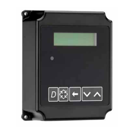
TIMER OPERATION Setting the Time of Day NOTE: Set Time of Day on the Lead Unit (#1) and the rest of the units in the system will update the Time of Day within 10 seconds. 1. Press and hold the Up or Down button for 2 seconds. CYCLE 1 00:00:00 2. -
Page 4: System Definitions
SYSTEM DEFINITIONS System System # of Type Operation Discussion Number Description Tanks/ Controls Single Unit Time Clock: No Meter Single tank configuration. Immediate: One Meter Delayed: One Meter Remote Signal Start: No Meter Interlocked 2, 3, or 4 Immediate: All Meters All tanks in parallel supplying treated water. -
Page 5: System Operation In Service (System 14-Demand Recall)
SYSTEM OPERATION IN SERVICE (SYSTEM 14-DEMAND RECALL) 5. The third valves returns to stand by as demand decreases The system operates as part of a multi-valve regeneration past the second trip point. system. Each valve in the system will have an active flow meter input, even in Standby. -
Page 6: Flow In A Four-Unit Sytem (System 14-Demand Recall)
FLOW IN A FOUR-UNIT SYTEM TIMER DISPLAY FEATURES (SYSTEM 14-DEMAND RECALL) Valve State Display Screen (SBY, SRV, INI, CHG, LCK) Time of Day alternates Steady Flow: with Error Screen Valve Example: Valve #, Volume Address Remaining, Errors System Flow Time Number Indicator of Day... -
Page 7: Timer Display - Screen Examples (System 4 Through 6)
TIMER DISPLAY - SCREEN EXAMPLES TRANSFORMER AND GROUND (SYSTEM 4 THROUGH 6) CONNECTIONS 1. In Service: System 4 Time Clock 2750/2850/2900 Valves: Communication Cables 03:45PM Ground label REGEN IN 07 DAYS 2. In Service: System 4 Flow Meter Initiated or System 4 Flow Meter Delayed Ground Wire from Transformer... -
Page 8: Network/Communication Cables And Connections 8 Master Programming Mode Flow Chart
NETWORK/COMMUNICATION CABLES MASTER PROGRAMMING MODE AND CONNECTIONS FLOW CHART Before entering Master Programming, please Use either a CAT3 or CAT5 Network/Communication cable. CAUTION contact your local professional water dealer. Connect the network/communication cable first before NOTE: Depending on current option settings, some displays programming. - Page 9 2750 (Default) 2750 Example: VALVE ADDRESS: Options: 2750 (Default) Valve Address #2 (Second Control Valve) (Default) 2815 MASTER PROGRAMMING MODE FLOW 2850 Options: Valve Address #1 (First Control Valve) 2900 Valve Address #2 (Second Control Valve) (Default) 3150 CHART continued Valve Address #3 (Third Control Valve) 3900 Valve Address #4 (Fourth Control Valve)
- Page 10 TRIP DELAY 2: Example: REGENERATION 30 SECONDS 2:00 A.M. (Default) TIME: 02:00AM MASTER PROGRAMMING MODE Options: A.M. (U.S. Format) FLOW CHART continued HR (Metric Format) NOTE: Display will not appear unless timer is programmed as valve position #1. System size must be 3 or 4 to appear. Use the Shift button to move one NOTE: Regeneration time will not appear unless Regeneration Day Override space to the left.
-
Page 11: User Programming Mode Flow Chart
Example: MAXIMUM FLOW MASTER PROGRAMMING MODE FLOW DIAGNOSTIC PROGRAMMING MODE Maximum Flow Rate of 0 gpm RATE: 0000 gpm CHART continued FLOW CHART Range: 20 - 2000 gpm (U.S. Format) 20 - 2000 L (Metric Format) NOTE: Only displayed if “Generic” is chosen for the flow meter. Entering Diagnostic Programming Mode 1. - Page 12 12 • Fleck 3200 NXT...
-
Page 13: 2750/2850/2900S Upper & 2900S Lower Powerhead Assembly
2750/2850/2900S UPPER & 2900S LOWER POWERHEAD ASSEMBLY 14 17 28 29 37 35 61501-3200NXT-2_Page2_REVA Fleck 3200 NXT • 13... - Page 14 2750/2850/2900S UPPER & 2900S LOWER POWERHEAD ASSEMBLY continued Item No. Part No. Description Item No. Part No. Description 1....1 ..18697-15 ....Backplate, Hinged 40 ....1 ..42580 ....Motor, Drive, 24V, 50/6 0Hz, Sp 2....1 ..60219-02 ....Cover Assy, Environmental, Black 41 ....1 ..
-
Page 15: 3150/3900 Upper & Lower Powerhead Assembly
3150/3900 UPPER & LOWER POWERHEAD ASSEMBLY 32 52 10 8 27 26 11 Fleck 3200 NXT • 15... - Page 16 3150/3900 UPPER & LOWER POWERHEAD ASSEMBLY continued Item No. Part No. Description Item No. Part No. Description 1....1 ..19304-04 ....Backplate, 3150/3900 37 ....1 ..14202-01 ....Screw, Hex Wsh, 8-32 X 5/16 2....1 ..15120 ....Bracket, Motor MTG, 3150/3900 38 ....1 ..17421 ....Plug, 1.20 Hole 3....1 ..
-
Page 17: Meter Assembly Plastic
METER ASSEMBLY PLASTIC Item No. Part No. Description Item No. Part No. Description 1 ....1 ..17542 ....Flow Straightener, 1-1/2" 20 ......61560 ....Meter Assy, 1-1/2" INLN, ELEC, PLAS, w/o Nipples, TURB 2 ....2 ..40576 ....Clip, H, Plastic, 7000 .. -
Page 18: 1-Inch Brass Meter Assembly
1-INCH BRASS METER ASSEMBLY Item No. Part No. Description 1....1 ..14716 ....Meter Cap Assy, Elec, Plastic Paddlewheel 2....1 ..13847 ....O-ring, -137 3....1 ..17798 ....Screw, Slot Hex WSH HD 4....4 ..12473 ....Screw, Hex WSH, 10-24 x 5/8 5....1 .. -
Page 19: 1-Inch Stainless Steel Meter Assembly
1-INCH STAINLESS STEEL METER ASSEMBLY Item No. Part No. Description 1....1 ..62049-01 ....Service Kit, 1 inch & 1-1/2 inch Meter, Standard Range 1 ..62049-02 ....Service Kit, 1 inch & 1-1/2 inch Meter, Extended Range 2....1 ..61932-10 ....Meter Assy, 1 inch, Inline, Stainless Steel, NPT, Standard Range 1 .. -
Page 20: 1-1/2 Inch Brass Meter Assembly
1-1/2 INCH BRASS METER ASSEMBLY Item No. Part No. Description Item No. Part No. Description 1....1 ..14716 ....Meter Cap Assy, Elec, Plastic 13 ....1 ..19121 ....Meter Cable Assembly, Paddlewheel ..19121-08 ....Meter Cable Assembly, 35 inch long with connector 2....1 .. -
Page 21: 1-1/2 Inch Stainless Steel Meter Assembly
1-1/2 INCH STAINLESS STEEL METER ASSEMBLY Not Shown (optional) Item No. Part No. Description 1 ..62072 ....Meter Sleeve, 1....1 ..62049-01 ....Service Kit, 1-1/2 inch to 1 inch (optional) 1 inch & 1-1/2 inch Meter, Standard Range 1 ..62049-02 ....Service Kit, 1 inch &... -
Page 22: Inch Brass Meter Assembly
2 INCH BRASS METER ASSEMBLY Item No. Part No. Description Item No. Part No. Description 1....1 ..14456 ....Body, Meter 2" 17 ......60616 ....Meter Assy, 2" INLN, NPT, ELEC, BRS, PDL 1 ..14456-20 ....Body, Meter, 2", BSP,Metric ..60616NP ....Meter Assy, 2" INLN, NPT, ELEC, 1 .. -
Page 23: Inch Stainless Steel Meter Assembly
2 INCH STAINLESS STEEL METER ASSEMBLY Item No. Part No. Description Item No. Part No. Description 1....1 ..62048-01 ....Service Kit, 2 inch Meter, 4....1 ..19791 ....Meter Cable Assembly, Standard Range ..19791-02 ....Meter Cable Assembly, 1 ..62048-02 ....Service Kit, 2 inch Meter, 28 inch long with connector Extended Range .. -
Page 24: Inch Brass Meter Assembly
3 INCH BRASS METER ASSEMBLY Item No. Part No. Description Item No. Part No. Description 15 ....1 ..19121 ....Meter Cable Assembly, 1....1 ..14716-01 ....Meter Cap Assy, 3" ELEC, Plastic, Paddlewheel ..19121-08 ....Meter Cable Assembly, 2....1 ..17798 ....Screw, Hex Washer Head, #8-16 35 inch long with connector x 0.38 .. -
Page 25: Inch Stainless Steel Meter Assembly
3 INCH STAINLESS STEEL METER ASSEMBLY Item No. Part No. Description 1....1 ..62078-01 ....Service Kit, 3 Inch Meter, Standard Range 1 ..62078-02 ....Service Kit, 3 Inch Meter, Extended Range 2....1 ..61935-10 ....Meter Assy, 3 Inch, Inline, Stainless Steel, NPT, Standard Range .. -
Page 26: Single Piston Wiring Diagram
SINGLE PISTON WIRING DIAGRAM OPTIONAL MOTOR/PUMP ON DURING REGENERATION OR CPO DEVICE ON DURING SERVICE (N.O. OUTPUT) SWITCHED HOT NEUTRAL 24VAC/3A MAX. RESISTIVE 30VDC/3A MAX. RESISTIVE UNSWITCHED HOT OPTIONAL INTERLOCK SWITCH (N.O.) *ONLY AVAILABLE ON 3200NXT AND 3214NXT OPTIONAL REMOTE -CLOSED CONTACT PREVENTS REGENERATION SIGNAL START -INPUT SIDE PULLED UP TO 32 VDC... -
Page 27: Dual Piston Wiring Diagram
DUAL PISTON WIRING DIAGRAM OPTIONAL MOTOR/PUMP ON DURING REGENERATION OR CPO DEVICE ON DURING SERVICE(N.O.OUTPUT) SWITCHED HOT NEUTRAL 24VAC/3A MAX. RESISTIVE 30VDC/3A MAX. RESISTIVE UNSWITCHED HOT OPTIONAL INTERLOCK SWITCH (N.O.) *ONLY AVAILABLE ON 3200NXT AND 3214NXT -CLOSED CONTACT PREVENTS REGENERATION OPTIONAL REMOTE -INPUT SIDE PULLED UP TO 32 VDC SIGNAL START... -
Page 28: Remote Timer Wiring Diagram
REMOTE TIMER WIRING DIAGRAM WHITE/BLACK STRIPE RED/BLACK STRIPE BLUE/WHITE STRIPE BLUE/BLACK STRIPE CAN2 CAN1 WHITE GREEN/BLACK STRIPE 24V AC BELDEN 9458 OR EQUIVALENT METER UPPER DRIVE BLUE ORANGE ORANGE/BLACK STRIPE 31.8 BLACK 1.25 BLACK/WHITE STRIPE RED/WHITE STRIPE GREEN/WHITE STRIPE GREEN BACKPLATE GROUND SCREW CABLE ENTRY SEAL... -
Page 29: 2750/2850 Remote Timer Wiring Diagram
2750/2850 REMOTE TIMER WIRING DIAGRAM TB1-GREY WHITE NEUTRAL WHITE LINE GREEN EARTH GND NOT USED BLUE BLACK TYPICAL OUTPUT WIRING GREY NOT USED TB1-GREY LD SWITCH PINK NEUTRAL LINE NOT USED EARTH GND #RED +5 VDC TB2-ORANGE #RED/BLACK DC GROUND P/N 19781 BLACK NEUTRAL... -
Page 30: 2900 Remote Timer Wiring Diagram
2900 REMOTE TIMER WIRING DIAGRAM TB1-GREY WHITE WHITE NEUTRAL WHITE LINE GREEN EARTH GND NOT USED BLUE BLACK NOT USED GREY BLACK LD SWITCH PINK NOT USED #RED +5 VDC TB2-ORANGE #RED/BLACK DC GROUND P/N 19781 BLACK GREEN #WHITE STEP WHITE #BLUE LOCKOUT... -
Page 31: 3900 Remote Timer Wiring Diagram
3900 REMOTE TIMER WIRING DIAGRAM TB1-GREY WHITE WHITE NEUTRAL WHITE LINE GREEN EARTH GND NOT USED BLUE BLACK GREY NOT USED BLACK LD SWITCH PINK NOT USED #RED +5 VDC TB2-ORANGE #RED/BLACK DC GROUND P/N 19781 BLACK GREEN #WHITE WHITE STEP #BLUE LOCKOUT... -
Page 32: 3150 Remote Meter Wiring Diagram
3150 REMOTE METER WIRING DIAGRAM TB1-GREY WHITE NEUTRAL WHITE LINE GREEN EARTH GND NOT USED BLUE BLACK GREY NOT USED NOT USED PINK NOT USED #RED +5 VDC TB2-ORANGE #RED/BLACK DC GROUND P/N 19781 BLACK #WHITE STEP WHITE #BLUE LOCKOUT #WHITE/BLACK HOME SENSOR... -
Page 33: Troubleshooting
TROUBLESHOOTING Detected Errors If a communication error is detected, an Error Screen will alternate with the main (time of day) screen every few seconds. • All units In Service remain in the In Service position. • All units in Standby go to In Service. •... - Page 34 34 • Fleck 3200 NXT...
- Page 35 Fleck 3200 NXT • 35...
- Page 36 For a detailed list of where Pentair trademarks are registered, please visit waterpurification.pentair.com/brands. § Pentair trademarks and logos are owned by Pentair plc or its affiliates. Third party registered and unregistered trademarks and logos are the property of their respective owners.
Need help?
Do you have a question about the FLECK NXT TIMER and is the answer not in the manual?
Questions and answers