Table of Contents
Advertisement
Quick Links
Download this manual
See also:
Manual
R
333 Bayview Avenue
Amityville, New York 11701
For Sales and Repairs, (800) 645-9445
For Technical Service, (800) 645-9440
Publicly traded on NASDAQ
Symbol: NSSC
© NAPCO 2005
GENERAL DESCRIPTION
The NAPCO Freedom Deadbolt-Activated Home Protection
System, a revolutionary new concept in residential security, com-
bines intuitive interactive arming with a passive disarming scheme,
providing a system which is not only effortless to use, but also
100% false alarm resistant during the critical arming and disarming
sequences.
The system is armed with a simple push of a button (L
or M) on the F-TP Touchpad control module, followed by the
locking of the home's deadbolt. To disarm, simply unlock the
deadbolt.
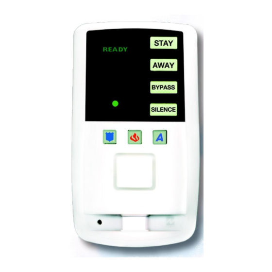
The microprocessor controlled F-TP Touch-
pad receives information regarding the status of the
deadbolt and door through its integral receiver,
from the F-LTRANS wireless transmitter and an
integral PIR sensor to ensure fool-proof operation.
The F-LTRANS wireless transmitter deter-
mines the status of the deadbolt (locked or
unlocked) through the F-TAB deadbolt sensor,
which is installed in the deadbolt strike hole. The
door status (open or closed) is supplied to the F-
LTRANS wireless transmitter via a reed switch or
door contact sensor (not provided) wired into it.
This information is transmitted to the wireless re-
ceiver inside the F-TP Touchpad, and is used to
arm and/or disarm the system. There are no mov-
ing parts in the F-TAB deadbolt sensor to break or
wear out; its adaptive inductive system ensures
trouble free use. If the position of the bolt in the
deadbolt strike hole changes over time due to the
door sagging, deadbolt replacement, etc., the F-TP
Touchpad microprocessor will automatically ac-
count for, and make, the necessary adjustments for these
changes.
The F-TP Touchpad's integral wide-angle PIR motion sensor
acts as an occupancy sensor that provides the microprocessor
with activity information which prevents the user from making er-
rors during the critical exit and entry periods. For example, if the
User presses the AWAY button, opens and closes the door and
locks the deadbolt but does not leave, the PIR will sense the
User's presence in the home and automatically default to STAY
mode arming, preventing a false alarm.
If the system is armed in the AWAY mode, the F-TP Touch-
pad PIR will generate an alarm if an intruder is detected. After an
intruder has been detected, the system may only be silenced by
inserting the F-IFOB digital key into the F-IFOB slot on the F-TP
Touchpad.
By allowing this level of system control without traditional
numeric keypad interaction, the NAPCO Freedom System will pro-
vide a significant reduction in false alarms due to user error and
also provide comfortable use of the system to those customers
whose technophobic tendencies would prevent them from arming
This manual contains the Installation Instructions for the F-TP Touchpad, F-TAB deadbolt sensor and the F-LTRANS wireless trans-
mitter. It is intended to be used in conjunction with the F-8 Panel Installation Instructions (WI1431)
FREEDOM Wireless
F-TP Touchpad, F-LTRANS and F-TAB
INSTALLATION INSTRUCTIONS
and the F-8 Panel Programming Instructions (WI1432).
and disarming the system using a traditional keypad.
The NAPCO Freedom System is also designed to prevent
the arming of the alarm system if all deadbolts are not engaged, a
high security feature normally found only in very elaborate high-
end installations.
INTEGRAL WIRELESS RECEIVER
The F-TP Touchpad incorporates an integral RF receiver.
This receiver receives transmissions ONLY from the F-LTRANS
wireless transmitter (no other transmitters will work with this re-
ceiver). The system uses two different frequencies to reduce
"nulls" and prevent noise on a single frequency from disrupting
communication. Rolling codes are also used to
prevent transmissions from being recorded and re-
transmitted to defeat the system.
The minimum free air distance is about 600 feet,
but walls and other obstructions may significantly
reduce this distance.
should never have a range problem as it should be
placed within the same room as the F-TP Touch-
pad as required for the integral PIR to protect the
interior deadbolt latch. However, the signal range
should be taken into account when considering the
use of a second transmitter to optionally protect a
second door / deadbolt.
INSTALLATION
The NAPCO Freedom System utilizes the home's
existing deadbolts and requires only that the F-
TAB deadbolt sensor be installed into the deadbolt
strike hole in the door jamb. This sensor enables
the system to detect the status of the deadbolt and
is compatible with all ¾" diameter deadbolts with a
5/8" throw or greater. Simply remove the strike plate and dust cup,
run the 2 conductor wire from the deadbolt hole to a F-LTRANS
wireless transmitter, and insert the F-TAB deadbolt sensor into the
strike hole. The F-TP Touchpad installs on a 4-wire bus and also
includes an integral siren that produces 85 dB (at 10 feet) as re-
quired for UL Residential Burglar and Fire. The Touchpad does
not have to be located next to the door, but can be mounted any-
where that allows the integral PIR to protect the door latch, and
allows the user to hear the siren chirp when exiting and arming
AWAY. The F-LTRANS wireless transmitter is typically mounted
adjacent to the doorframe. It may be mounted high enough to be
unobtrusive, yet accessible for inspection and battery replacement.
The F-TP Touchpad includes 1 optional on-board input for
an auxiliary device such as a motion sensor, glass-break detector
or other device. In less time than it takes to install a traditional key-
pad, this comprehensive module consisting of the Touchpad,
deadbolt sensor, door contact, motion sensor and siren can be
installed.
NOTE: If protecting a door with glass panels or side lights,
WI1439 10/05
The Primary transmitter
1
Advertisement
Table of Contents

Related Manuals for NAPCO Freedom Wireless


Summary of Contents for NAPCO Freedom Wireless
-
Page 1: General Description
© NAPCO 2005 and disarming the system using a traditional keypad. GENERAL DESCRIPTION The NAPCO Freedom System is also designed to prevent The NAPCO Freedom Deadbolt-Activated Home Protection the arming of the alarm system if all deadbolts are not engaged, a... - Page 2 an acoustic glass-break sensor (connected to the F-TP Touchpad Aux. Zone) should be installed to insure the integrity of the system. TRANSMITTER AND RECEIVER OPERATION When learning transmitters into the F-TP Touchpad re- POWER ceiver, it is necessary to keep the Touchpad faceplate open in The F-TP Touchpad is powered by the keypad bus of the order to examine the receiver LED and operate the Mode button F-8 Control Panel.
- Page 3 Installing the NAPCO F-TP Touchpad, F-TAB Deadbolt Sensor and the F-LTRANS wireless transmitter MOUNT AND WIRE THE F-TP TOUCHPAD Open F-TP Mark the holes. Touchpad. Remove The F-TP Touchpad can be mounted 60” anywhere, provided its PIR directly front TOP UP...
- Page 4 To increase the depth of the dead- Locate the F-LTRANS bolt hole, use a 1" spade bit wireless transmitter: (shown). Mount the F-LTRANS inside a Possible mounting drop ceiling, above the door locations Remove the remaining wood from the frame, or in any location suitable deadbolt hole opening using a rotary wood for the installation (see illustration rasp.
- Page 5 LEARN TRANSMITTERS AND TEST SYSTEM Prepare Receiver Multiple Transmitters--Notes Learn Transmitters With all wiring in place, apply The Primary transmitter that is lo- power to the control panel. (the cated in the same room as the Jumper not installed Touchpad receiver will power up) Touchpad designated To ensure that the receiver is...
- Page 6 F-TP Touchpad Wiring Diagram F-TP Touchpad Configuration Jumper JP1 JP1 Configuration F-TP Touchpad Address # 1 Jumper F-TP Touchpad Address # 2 F-TP Touchpad ADDR PIR≠ Address F-TP Touchpad PIR and AUX AUX2 Zone enabled as Zone 2 F-TP Touchpad NOTE: Cut JP3 if AUX Zone 2 Configuration Only F-TP Touchpad AUX...
-
Page 7: Activity Sensor
F-TP TOUCHPAD PIR The F-TP TOUCHPAD includes an integral PIR sensor which provides the following system functions: Activity Sensor 25’ The PIR is always gathering activity information which provides the system with data that is used to insure proper use of the sys- tem and prevent user errors. -
Page 8: System Overview
SYSTEM OVERVIEW F-LTRANS FREEDOM F-8 CONTROL PANEL (See WI1076 for more information) ADDR PIR≠ AUX2 N/C Magnetic Door Contact +FIRE FIRE BELL F-TP 16 VAC 20 VA PWR GND TRANSFORMER BLACK F-TAB-Sensor TRF12 (OR QUIVALENT GREEN SEE WI1076). Class 2 Transformer YELLOW DO NOT connect to switched outlet. -
Page 9: Troubleshooting
TROUBLESHOOTING covers on. Remove transmitter cover to be tested (cover TOUCHPAD LIGHTS (ON FRONT OF TOUCHPAD) FAIL TO TURN ON WHEN POWER APPLIED for all other transmitters must be installed). Check F-TP Touchpad power wires (terminals 1 and 2). Unlock and open door. While pressing and holding the tamper switch, insert battery as shown, then release tam- TOUCHPAD LIGHTS (ON FRONT OF TOUCHPAD) ALL... - Page 10 NOTES...
- Page 11 THIS PAGE INTENTIONALLY LEFT BLANK...
-
Page 12: Mounting Template
MOUNTING TEMPLATE 2 3/8” 6 1/4” Wire Access Hole 4 3/8” SINGLE- GANG (Cut in Wall) MOUNTING HOLES 3 5/16” 2.0” 3.5” * It may be necessary to drill a hole in the single-gang box to allow the antenna wire to be positioned straight down as shown in the previous installation instructions.
Need help?
Do you have a question about the Freedom Wireless and is the answer not in the manual?
Questions and answers