Table of Contents
Advertisement
Quick Links
Advertisement
Table of Contents

Subscribe to Our Youtube Channel
Related Manuals for HIKVISION HIK-1100KI


Summary of Contents for HIKVISION HIK-1100KI
-
Page 1: Network Keyboard
Network Keyboard User Manual UD01314B... - Page 2 Any and all information, including, among others, wordings, pictures, graphs are the properties of Hangzhou Hikvision Digital Technology Co., Ltd. or its subsidiaries (hereinafter referred to be “Hikvision”). This user manual (hereinafter referred to be “the Manual”) cannot be reproduced, changed, translated, or distributed, partially or wholly, by any means, without the prior written permission of Hikvision.
-
Page 3: Regulatory Information
User Manual of DS-1100KI Network Keyboard Regulatory information FCC information Please take attention that changes or modification not expressly approved by the party responsible for compliance could void the user’s authority to operate the equipment. FCC compliance: This equipment has been tested and found to comply with the limits for a Class A digital device, pursuant to part 15 of the FCC Rules. - Page 4 User Manual of DS-1100KI Network Keyboard Safety Instruction These instructions are intended to ensure that user can use the product correctly to avoid danger or property loss. The precaution measure is divided into “Warnings” and “Cautions” Warnings: Serious injury or death may occur if any of the warnings are neglected. Cautions: Injury or equipment damage may occur if any of the cautions are neglected.
- Page 5 User Manual of DS-1100KI Network Keyboard Preventive and Cautionary Tips Before connecting and operating your keyboard, please be advised of the following tips: • Ensure unit is placed in a well-ventilated, dust-free environment. • Keep all liquids away from the keyboard. •...
- Page 6 User Manual of DS-1100KI Network Keyboard Applicable Models This manual is applicable to the model listed in the following table. Series Model Network Keyboard DS-1100KI Symbol Conventions The symbols that may be found in this document are defined as follows. Symbol Description Indicates a potentially hazardous situation, which if not avoided,...
-
Page 7: Table Of Contents
User Manual of DS-1100KI Network Keyboard Table of Contents Chapter 1 Introduction ......................... 10 1.1 Overview ..........................10 1.2 Features ..........................10 1.3 Appearance ......................... 11 Chapter 2 Operation Guide ......................13 2.1 User Account ........................13 2.2 Indicators and Buttons ......................13 2.3 Button Operation ........................ - Page 8 User Manual of DS-1100KI Network Keyboard 4.3.1 Network Settings ....................42 4.3.2 Serial Port Settings ....................43 4.3.3 Camera Settings ..................... 43 4.3.4 Alarm Settings ......................53 4.3.5 Exceptions ......................56 4.3.6 Maintenance ......................56 4.3.7 Stream Media Settings ................... 57 4.3.8 Remote Panel Settings ....................
- Page 9 User Manual of DS-1100KI Network Keyboard 5.3 Displaying Decoded Video to Output Channel ..............78 5.3.1 Setting Multi-Division Display ................78 5.3.2 Displaying Video to Output Channel ..............79 5.3.3 Displaying Video of Camera Group to Output Channel ........80 5.3.4 Displaying Video of Camera Group to the Window of Output Channel ....
- Page 10 User Manual of DS-1100KI Network Keyboard 6.3.2 Operating Matrix Access Gateway ............... 118 6.3.3 Operating PTZ Control ..................118 6.4 Accessing by iVMS Platform ................... 119 6.4.1 Logging in to the iVMS Platform ................ 119 6.4.2 Managing Input Channel ..................119 6.4.3 Managing Output Channel ...................
-
Page 11: Chapter 1 Introduction
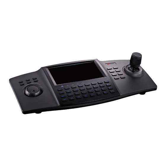
User Manual of DS-1100KI Network Keyboard Chapter 1 Introduction 1.1 Overview DS-1100KI Network Keyboard can be used to control the camera/speed dome, display decoded video on video wall, control matrix, as well as support 1 channel of live view at up to 1080P resolution. Designed with touch screen, it is easy to operate and configure settings. -
Page 12: Appearance
User Manual of DS-1100KI Network Keyboard Display of Decoded Video to Output Channel Display of decoded camera on selected window of output channel; Display of decoded camera group on selected window of output channel; Cycle display of decoded camera group to the output channel; ... - Page 13 User Manual of DS-1100KI Network Keyboard Table 1.2 Description of Interfaces Serial No. Description Serial No. Description Touch pen Line in Audio out Reserved interface RS-485 interface LAN interface RS-232 interface USB interface 12 VDC power supply Power on/off...
-
Page 14: Chapter 2 Operation Guide
User Manual of DS-1100KI Network Keyboard Chapter 2 Operation Guide User Account The keyboard user account is classified to two types: the admin and the operator. The admin user is authorized with the following operation permissions: 1. Add a maximum of 3 operators; 2. - Page 15 User Manual of DS-1100KI Network Keyboard network. Tx/Rx Flickers when the keyboard is transmitting/receiving data. Reserved ALARM Reserved Refer to Figure 2.3 for the functional buttons on the front panel. • Functional Buttons: Figure 2.3 Functional Buttons Refer to Table 2.2 for the description of the functional buttons. Table 2.2 Description of Functional Buttons MON-G CAM-G...
- Page 16 User Manual of DS-1100KI Network Keyboard Figure 2.4 Numeric Buttons • 4-axis Joystick: Use the joystick to realize pan and tilt movement at 8 directions. The 4-axis joystick can be used to control the zoom; and the central button is used as Enter button or you can press it to capture picture.
-
Page 17: Button Operation
User Manual of DS-1100KI Network Keyboard Figure 2.6 Playback Control Refer to Table 2.3 for the description of playback control. Table 2.3 Description of Playback Control Backward 5min Stop Record Play/Pause Previous File Next File 2.3 Button Operation 2.3.1 Operating Video Wall Display Refer to Table 2.4 for the description of video wall display buttons. -
Page 18: Ptz Control Buttons
User Manual of DS-1100KI Network Keyboard SET+Num+TOUR/GROUP/PATROL/PATTERN: Press the SET+1+PATTERN buttons to set the the tour, group, patrol and pattern. pattern 1. TOUR SET+Num+TOUR: set the tour. Press the SET+1+TOUR buttons to set the tour 1. Num+TOUR: call the defined tour. Press the 1+TOUR buttons to call the pre-defined tour 1. -
Page 19: Input Method Shift
User Manual of DS-1100KI Network Keyboard 2.4 Input Method Shift Tap the icon on the soft keyboard to enter the interface for inputting the English letters, and the icon can be used to switch the uppercase/lowercase. Figure 2.7 English Input Method Tap the icon on the soft keyboard to enter the interface for inputting the numerals. -
Page 20: Quick Configuration Guide
User Manual of DS-1100KI Network Keyboard Admin: For the first time to operate the keyboard, you should configure the keyboard parameters in Keyboard Configuration menu, add device and operator, and then link the added device to the assigned operator. Operator: The operator is allowed to operate local live view, remote configuration of encoder/decoder parameters, display of decoded video to output channel, local playback, PTZ control, AUX functions, etc. - Page 21 User Manual of DS-1100KI Network Keyboard Figure 2.12 Admin Main Interface Settings the Network Steps: Enter the Network Settings interface. Keyboard > Network Configure the network settings of the keyboard, including the Port, IP Address, Subnet Mask, Default Gateway, Preferred DNS, Alternate DNS and MAC Address. Tap Apply to save the settings. Figure 2.13 Network Settings Tap Return to return to the main interface.
- Page 22 User Manual of DS-1100KI Network Keyboard Return to the Device-Device List interface, and the successfully added device is shown on the list. You can add device in the three sheets including Encoder list for adding encoding devices such as IP camera, DVR, NVR, etc.
-
Page 23: Quick Operation
User Manual of DS-1100KI Network Keyboard Figure 2.18 Device Tap Add Device to enter the User-Add Device interface. Select the device by checking the checkbox, and tap Add to add the device for the current user. Figure 2.19 Add Device The added device (s) for the current user can be displayed on the User-Device interface. - Page 24 User Manual of DS-1100KI Network Keyboard display the decoded video on the selected window of the output channel. The following quick operations are two examples. For all the quick operations of the keyboard, refer to the Chapter 5 Keyboard Operation. ...
-
Page 25: Chapter 3 Local Keyboard Configuration By Admin
User Manual of DS-1100KI Network Keyboard Chapter 3 Local Keyboard Configuration by Admin Purpose: As an admin, you can configure the keyboard locally, or by WEB page. This chapter introduces the local keyboard configuration by the admin. Login Steps: Tap the Keyboard icon on the startup interface. Figure 3.1 Startup Interface Select admin on the login interface. -
Page 26: Changing The Password
User Manual of DS-1100KI Network Keyboard Figure 3.3 Activation STRONG PASSWORD RECOMMENDED–We highly recommend that you create a strong password of your own choosing (using a minimum of 8 characters, including upper case letters, lower case letters, numbers, and special characters) in order to increase the security of your product. We recommend that you reset your password regularly, especially in the high security system, resetting the password monthly or weekly can better protect your product. -
Page 27: Keyboard Management
User Manual of DS-1100KI Network Keyboard Figure 3.5 User List Input the Current Password and New Password and confirm the New Password. Figure 3.6 Change Password If the password you set is too simple, the message box as shown in Figure 3.5 will pop out to remind you to reset the password. -
Page 28: Viewing Version Information
User Manual of DS-1100KI Network Keyboard parameters, configure hardware settings, adjust time, select language, calibrate the screen and upgrade system. 3.3.1 Viewing Version Information Tap Version to enter the Keyboard-Version interface to view the current version information of the keyboard. Figure 3.8 Version Information 3.3.2 Configuring Network Steps:... -
Page 29: Configuring Time
User Manual of DS-1100KI Network Keyboard Configure the Sound Effect, Alarm Sound, Key Light, Keyboard Lock Delay, Screen Off Delay, Background Contrast, Mouse Speed and Screen Brightness. Sound Effect/Alarm Sound/Key Light: Check the corresponding checkbox to to enable the function, or remain it as to disable the function. -
Page 30: Configuring Language
User Manual of DS-1100KI Network Keyboard Figure 3.11 Time Settings 3.3.5 Configuring Language Steps: Tap Language to enter the Keyboard-Language Settings interface. to select English as the system language. Tap Apply to save the setting. Figure 3.12 Language Settings 3.3.6 Calibrating Screen Purpose: In order to use the touch screen correctly, it needs to calibrate the screen positioning properly. -
Page 31: Upgrading Device
User Manual of DS-1100KI Network Keyboard Figure 3.13 Screen Calibration The system will pop up the hint message box. Tap Yes to continue the calibration. Figure 3.14 Hint Box Use the touch pen to tap the three spots marked as “+” by following the hints. Figure 3.15 Tap the Spots The system will pop up the hint “Screen calibration completed.”. - Page 32 User Manual of DS-1100KI Network Keyboard You must create the FTP server connection first by TFTP or WFTP in PC before operating the FTP upgrade. Please refer to Chapter 8.2 Upgrade by FTP for the upgrading. Figure 3.17 Upgrade by FTP If the upgrading is failed, the corresponding error message box will pop up.
-
Page 33: Device Management
User Manual of DS-1100KI Network Keyboard Option 3: Upgrading by WEB Browser You can refer to Chapter 7.1.6 Maintenance for the steps of upgrading by WEB browser. 3.4 Device Management Purpose: You can add, edit and delete devices in Device Management interface. Three kinds of devices can be added. Encoder list for adding encoding devices such as IP camera, DVR, NVR, etc. -
Page 34: Editing/Deleting The Device
User Manual of DS-1100KI Network Keyboard Figure 3.21 Auto Search After the searching is completed, the information of the searched devices will be displayed in the list. Check the checkbox of the device from the list, and then input the login user name and password. Tap Add to add the selected device. -
Page 35: User Management
User Manual of DS-1100KI Network Keyboard Edit the device name, user name, password and protocol. Figure 3.23 Edit the Device If the password is too simple, a message box “Risky password” will pop out to remind you the password is unsafe, and you have to reedit the password. -
Page 36: Adding A User
User Manual of DS-1100KI Network Keyboard Figure 3.25 User Management 3.5.1 Adding a User Steps: Tap Add User to enter the User-Add User interface. Figure 3.26 Add User Input the User Name, Password and confirm the Password. If the password is too simple, a message box “Risky password” will pop out to remind you the password is unsafe, and you have to reset the password. - Page 37 User Manual of DS-1100KI Network Keyboard On the User-User List interface, tap to enter the User-Device interface. Figure 3.27 Device Interface Select the operator from the Operator drop-down list. Tap Add Device to enter the User-Add Device interface. Select the device by checking the checkbox, and tap Add to add the device for the current user.
-
Page 38: Editing/Deleting The User
User Manual of DS-1100KI Network Keyboard 3.5.3 Editing/Deleting the User Editing the User Steps: On the User-User List interface, tap to enter the Change Password interface. Figure 3.30 Change Password for the Operator Input the Current Password, New Password and confirm the New Password for the admin. Input the New Password and confirm the New Password for the operator ... -
Page 39: Restoring To Default Settings
User Manual of DS-1100KI Network Keyboard Importing Configuration File Steps: Insert the USB flash disk to the USB interface on the keyboard. Select the configuration file from the disk. Tap Import to import the configuration file. Figure 3.32 Import Configuration File If the imported configuration file is incorrect, the message box “Importing file failed: file type mismatched”... -
Page 40: Logout
User Manual of DS-1100KI Network Keyboard Select restoring type in the pop-up menu. Figure 3.34 Restore to Default Settings Tap Yes to continue the operation, or No to cancel the operation. 3.8 Logout Steps: Tap Logout on the admin main interface, and the message box “Logout now?” pops up. Figure 3.35 Logout Tap Yes to confirm the logout, or No to cancel the operation. -
Page 41: Chapter 4 Local Keyboard Configuration By Operator
User Manual of DS-1100KI Network Keyboard Chapter 4 Local Keyboard Configuration by Operator Purpose: As an operator, you can configure the keyboard locally, or by WEB page. This chapter introduces the local keyboard configuration by the operator. 4.1 Login Purpose: You can log in to the operator main interface in two ways. -
Page 42: Viewing Device List
User Manual of DS-1100KI Network Keyboard Figure 4.2 Operator Login (2) Tap Yes to log in to the operator main interface. Figure 4.3 Operator Main Interface 4.2 Viewing Device List Tap Device List on the main interface to enter the Device List interface. The list displays all devices which can be controlled by the current login user. -
Page 43: Encoding Device Settings
User Manual of DS-1100KI Network Keyboard should be the integral multiple of 1000. It will increase progressively according to the added order. 4.3 Encoding Device Settings Purpose: You can configure the settings for network, RS-232/RS-485 serial port, camera, alarm, exception, stream media, remote panel etc. -
Page 44: Serial Port Settings
User Manual of DS-1100KI Network Keyboard 4.3.2 Serial Port Settings Steps: Tap Serial on the Remote Settings interface to enter the Serial Port Settings interface. Figure 4.7 Serial Port Settings Tap Set to set the RS-232 and RS-485 port parameters. Figure 4.8 RS-232Settings Figure 4.9 RS-485 Settings 4.3.3 Camera Settings... - Page 45 User Manual of DS-1100KI Network Keyboard Figure 4.10 Camera Settings You can configure the OSD settings, video parameters, record settings, motion detection, video loss detection, tampering alarm, privacy mask, and IPC management (for hybrid DVR and NVR only). Configuring OSD Settings Steps: Tap Set of the OSD Settings to enter the OSD Settings interface.
- Page 46 User Manual of DS-1100KI Network Keyboard Figure 4.12 Video Parameters Settings Select the camera for configuration from the dropdown list of Camera. Set the Encoding Parameters, Stream Type, Resolution, Frame Rate, Bit Rate Type, Max. Bit Rate, and Image Quality. Tap Copy to copy the video parameters to the other cameras.
- Page 47 User Manual of DS-1100KI Network Keyboard Check the checkbox of Enable Schedule item. Select the day you want to set record schedule. You can also select it to All Week. To schedule an all-day recording, tap the checkbox of the All Day item. Select the recording type for the selected day to Continuous, Motion Detection, Alarm, Motion / Alarm or Motion &...
- Page 48 User Manual of DS-1100KI Network Keyboard reached, the file will be deleted. You can set the expired time to 0, and then the file will not be deleted. The actual keeping time for the file should be determined by the capacity of the HDD. ...
- Page 49 User Manual of DS-1100KI Network Keyboard Tap OK to save the settings and return to the Motion Detection Settings interface. Tap the Set button beside Arming Schedule to configure the arming schedule of motion detection for the current camera. You can also copy the arming schedule to the other days. Figure 4.19 Set Arming Schedule 10.
- Page 50 User Manual of DS-1100KI Network Keyboard Figure 4.22 Triggered Camera Settings 16. Check the checkbox(s) to trigger the camera(s) you select. Tap OK to save the settings and Cancel to return to the previous interface. 17. Tap Apply to save the current settings and Cancel to return to the previous interface. Configuring Video Loss Detection Purpose: Detect the video loss of a camera and take alarm response action(s).
- Page 51 User Manual of DS-1100KI Network Keyboard Figure 4.24 Set Arming Schedule Tap OK to save the settings and return to the Video Loss interface. If the Trigger Alarm Output is selected, you should tap the Set button to configure the triggered alarm output (s).
- Page 52 User Manual of DS-1100KI Network Keyboard the Set button to configure the triggered alarm output(s). Please refer to the triggered alarm output settings of motion detection for reference. Tap Apply to save the current settings and Cancel to return to the previous interface Configuring Privacy Mask Purpose: You are allowed to configure the four-sided privacy mask zones that cannot be viewed by the operator.
- Page 53 User Manual of DS-1100KI Network Keyboard Tap the IP Camera List tag to enter the IP Camera Management interface. Figure 4.29 IP Camera List Tap Add to enter the IP Camera Parameters interface. Figure 4.30 Set IP Camera Parameters Configure the Camera No., Registration Mode (IP address/domain name), IP address/Domain name, Port, User Name, Password, Channel No.
-
Page 54: Alarm Settings
User Manual of DS-1100KI Network Keyboard Tap Status to enter the Analog Camera Status interface. Figure 4.32 Analog Camera Status You can deselect the camera (s) to disable the analog camera(s) connected. 4.3.4 Alarm Settings Purpose: You can configure the alarm input, alarm output and manual alarm. Tap Alarm on the Remote Settings interface to enter the Alarm Settings interface. - Page 55 User Manual of DS-1100KI Network Keyboard Select the Alarm Input for configuration. Edit the Alarm Name. Select the Alarm Type to Normally Open or Normally Close. Set the handling action for the selected alarm input by checking the checkbox of Handling Alarm. Tap the Set button beside the Arming Schedule to set the arming schedule of the alarm input.
- Page 56 User Manual of DS-1100KI Network Keyboard Please refer to the User Manual of the current DVR for detailed instructions. Configuring Alarm Output Steps: Tap Set beside Alarm Output to enter the Alarm Output Settings interface. Figure 4.38 Set Alarm Output Select the Alarm Output for configuration.
-
Page 57: Exceptions
User Manual of DS-1100KI Network Keyboard 4.3.5 Exceptions Purpose: You can configure the exception handling method (s) for each exception type. Steps: Tap Exceptions on the Remote Settings interface to enter the Exception Settings interface. Figure 4.40 Set Exceptions Select the Exception Type to configure with handling method (s). E.g., ... -
Page 58: Stream Media Settings
User Manual of DS-1100KI Network Keyboard Figure 4.41 Device Maintenance Tap the Set button to set the corresponding parameters. HDD Management: Set and initialize HDD, and set HDD in group management. User Management: Add/edit/delete user account, and assign operating permissions for each user. ... -
Page 59: Remote Panel Settings
User Manual of DS-1100KI Network Keyboard device only. Tap Apply to save the settings. 4.3.8 Remote Panel Settings Purpose: The keyboard can control the front panel of the added DVR/NVR. Steps: Tap Remote Panel on the Remote Settings interface to enter the Remote Panel interface. Figure 4.43 Remote Panel Tap the buttons on the remote panel to control the front panel of the DVR/NVR. -
Page 60: Network Settings
User Manual of DS-1100KI Network Keyboard 4.4.1 Network Settings Steps: Tap Network on the Remote Settings interface to enter the Network Settings interface. Figure 4.45 Network Settings You can configure the General Settings, PPPoE, DDNS and NTP parameters of the decoder. Please refer to Chapter 4.3.1 Network Settings for reference. -
Page 61: Output Settings
User Manual of DS-1100KI Network Keyboard Figure 4.48 RS-485 Port Settings 4.4.3 Output Settings Purpose: You can configure parameters for the display of decoded output video on monitor. Steps: Tap Output on the Remote Settings interface to enter the Output Settings interface. Figure 4.49 Output Settings Select the display channel. -
Page 62: Video Wall Settings
User Manual of DS-1100KI Network Keyboard 4.4.4 Video Wall Settings Purpose: Decoding devices such as DS-6400HDI-T, DS-6400HDI-S, DS-6500HDI-T or DS-6900UDI-T can be added. The video wall display is supported. You can decode the video signal and display it on the video wall. Steps: Tap Video Wall on the Remote Settings interface to enter the Video Wall Settings interface. -
Page 63: Maintenance
User Manual of DS-1100KI Network Keyboard You can view the working status of each Decoding Channel, including the Decoding Status, Stream Type, Package Mode, Video/Audio Frame Rate, etc. 4.4.6 Maintenance Steps: Tap Maintenance on the Remote Settings interface to enter the Device Maintenance interface. Figure 4.52 Device Maintenance Tap Set to set the parameters below. -
Page 64: Starting Local Live View
User Manual of DS-1100KI Network Keyboard Figure 4.53 Input List 4.5.1 Starting Local Live View Steps: Select a channel from the input list and tap the icon to start the local live view. Figure 4.54 Local Live View You can press the NEXT or PREV button to view the video of the next or previous channel. Press ESC button to return to the input list. -
Page 65: Editing A Camera
User Manual of DS-1100KI Network Keyboard Figure 4.55 Channel-Zero Settings Select an encoding device from the list and tap the icon to enter the local live view by the channel-zero. The channel-zero must be supported by the connected encoding device and has been enabled. 4.5.3 Editing a Camera Steps: Select a camera from the Input Settings-Input List interface, and tap... -
Page 66: Output Settings
User Manual of DS-1100KI Network Keyboard Figure 4.57 Input Group Settings to select the Group No. from the drop-down list, set the Cycle Time for the group and tap the Save button. Up to 16 input groups can be added. ... -
Page 67: Playback On Monitor
User Manual of DS-1100KI Network Keyboard Figure 4.59 Output List 4.6.1 Playback on Monitor Purpose: Playback by file and playback by time are supported. Before operating the playback, you must configure the output settings first. Please refer to Chapter 4.4.3 Output Settings. Playback by File Steps: Select an output channel from the output list and tap the... - Page 68 User Manual of DS-1100KI Network Keyboard Tap Search to search the matched video files. The searching results can be viewed on the Playback File List interface. Figure 4.61 Search Result Select the file for playback from the list and tap Playback to play back the video file. The Playback Control buttons on the left side of the control panel are supported during the playback.
-
Page 69: Editing An Output Channel
User Manual of DS-1100KI Network Keyboard 4.6.2 Editing an Output Channel Steps: Select an output channel from the Output Settings-Output List interface, and tap to enter the Edit Output interface. Figure 4.63 Edit Output Edit the output No.. The Output No. should be set uniquely from 1 to 999999. 4.6.3 Setting Output Group Steps: Tap Output Group to enter the Output Settings-Output Group interface. -
Page 70: Setting Video Wall / Scene
User Manual of DS-1100KI Network Keyboard Figure 4.65 Add Output Select the outputs from the list to be added to the group, and then tap Add to add them. Tap OK to return to the Output Group interface, where you can view the successfully added output channels for the current group. -
Page 71: Macro Settings
User Manual of DS-1100KI Network Keyboard Tap OK button to save the setting. 4.7 Macro Settings Purpose: The macro command can be used for operating a series of continuous actions in sequence. You can press the “Num + MAC” keys to call the programmed macro command. Tap Macro on the main interface to enter the Macro Settings interface. -
Page 72: Viewing Macro
User Manual of DS-1100KI Network Keyboard 4.7.2 Viewing Macro Steps: After adding macro, return to the Macro List interface and you can view the added macro command. Figure 4.70 Macro List to view the macro command. Figure 4.71 View Macro You can tap Prev Page or Next Page to view the previous or next macro command. -
Page 73: Playback
User Manual of DS-1100KI Network Keyboard 4.8 Playback Purpose: The video files stored in the encoding device can be played back in the local keyboard. Three playback modes are available: playback by USB file, playback by time and playback by file. Tap Playback on the operator main interface to enter the Local Playback interface. -
Page 74: Playback By File
User Manual of DS-1100KI Network Keyboard Figure 4.74 Playback Interface 4.8.2 Playback by File Steps: Tap the By File tab on the Local Playback interface to enter the Playback by File interface. Figure 4.75 Playback by File Input the Camera No. for playback. Select the Record Type and File Type. -
Page 75: Playback By Time
User Manual of DS-1100KI Network Keyboard Select the file for playback from the list and tap Playback to play back the video file. 4.8.3 Playback by Time Steps: Tap the By Time tab on the Local Playback interface to enter the Playback by Time interface. Figure 4.77 Playback by Time Input the Camera No. -
Page 76: Auxiliary Key Settings
User Manual of DS-1100KI Network Keyboard edit the password for the current login user. Enter the Current Password and New Password, and then tap Apply to finish the password modification. Figure 4.79 Modify Password 4.9.2 Auxiliary Key Settings Steps: Tap Aux Key on the Advanced Settings interface to enter the Aux Key Settings interface. The Aux Key 1 and Aux Key 2 correspond to the AUX1 and AUX2 keys on the keyboard respectively. -
Page 77: Logout
User Manual of DS-1100KI Network Keyboard Figure 4.81 Performance Settings 4.10 Logout Steps: Tap Logout on the operator main interface, and the message box “Logout now?” will pop up. Tap Yes to confirm the logout, or No to cancel the operation. After logout of current login user, the system will return to the User Login interface. -
Page 78: Chapter 5 Keyboard Operation
User Manual of DS-1100KI Network Keyboard Chapter 5 Keyboard Operation 5.1 Shortcut Operation The operating user must log in to the keyboard to realize all shortcut operations (except LOCK). Shortcut Operation: Press the Num keys on the keyboard to enter the shortcuts operation interface. ... -
Page 79: Displaying Decoded Video To Output Channel
User Manual of DS-1100KI Network Keyboard Figure 5.2 Local Live View Press the ESC key on the keyboard to enter full-screen live view mode. Figure 5.3 Full-Screen Live View Up to 1080P resolution is supported for local live view. ... -
Page 80: Displaying Video To Output Channel
User Manual of DS-1100KI Network Keyboard Figure 5.4 Set Multi-Division Display Mode In the local live view mode when you input 0+MON keys, the multi-division display mode is not supported. Corresponding error message will appear on the screen when user performs wrong operation. E.g., when the multi-division number entered is not supported by the current output channel, the message “Window mode error.”... -
Page 81: Displaying Video Of Camera Group To Output Channel
User Manual of DS-1100KI Network Keyboard Table 5.1 Description of Icons Icon Description Switch to full screen output of the selected window. Restore from the full screen output of the selected window. Audio-off Audio-on For the B20 MVC, video wall controller, and decoder (such as DS-6400HDI-T, and DS-6400HDI-S) added to the device list, the Num in Step 1 is the sum of the segment No. -
Page 82: Displaying Video Of Camera Group To The Window Of Output Channel
User Manual of DS-1100KI Network Keyboard Figure 5.6 Display Video of Camera Group on Output Channel The dwell time for the cycle view is set in the input group settings interface. You can refer to Chapter 4.5.4 Setting Input Group. ... -
Page 83: Displaying Video Of Camera Group To Output Group
User Manual of DS-1100KI Network Keyboard Figure 5.7 Display Video of Camera Group to the Window of Output Channel The dwell time for the cycle view is set in the input group settings interface. You can refer to Chapter 4.5.4 Setting Input Group. -
Page 84: Displaying Video Of Camera Group To The Window Group
User Manual of DS-1100KI Network Keyboard 5.3.6 Displaying Video of Camera Group to the Window Group Purpose: In the condition of opening windows first via the iVMS 4200, you can drag the camera group to the window group one-time. Steps: 1. -
Page 85: Calling A Tour
User Manual of DS-1100KI Network Keyboard Press the Num + ENTER keys to set the camera No.. Repeat Step 4 to set other cameras. Press the SET key to finish the tour settings. Figure 5.10 Set a Tour When the device is restarted, all the tour settings will be invalid. ... -
Page 86: Setting A Group Tour
User Manual of DS-1100KI Network Keyboard Figure 5.11 Call a Tour 5.3.9 Setting a Group Tour Purpose: Multiple camera groups can be displayed on the specified output channels in tour respectively. Each user account is allowed to set up to 8 group tours, and each group can include 8 camera groups to specified output channels. When the system is not in the playback mode, user can directly press the SET key and then Num + GROUP keys to enter the group tour settings interface. -
Page 87: Calling A Group Tour
User Manual of DS-1100KI Network Keyboard 5.3.10 Calling a Group Tour Purpose: Multiple camera groups can be automatically displayed on related output channels respectively in tour by calling the configured group tour, e.g., camera group 1 on monitor 1, camera group 2 on monitor 2, etc. The dwell time of group tour can be configured. -
Page 88: Switching Video To The Screen
User Manual of DS-1100KI Network Keyboard The local playback by time is not supported. You can press the button to stop the instant playback. You can also rotate the outer ring of the shutter in clockwise direction to speed up the playback, with the max. -
Page 89: Ptz Control
User Manual of DS-1100KI Network Keyboard segment No. of B20 MVC is 1000, and the scene No. is 1, then the Num should be 1001. Press Num + MON keys to select the output channel. Press Num + WIN keys to select the screen (not for video wall). Press Num + CAM/CAM-G to switch the selected camera or camera group on the screen. -
Page 90: Calling A Preset
User Manual of DS-1100KI Network Keyboard then press the PRESET key to start preset settings. • Setting a Preset by Output Channel Steps: Press the Num + MON keys to select the output channel. Press the Num + WIN keys to select the display window. Operate the joystick to move PTZ to the desired position. - Page 91 User Manual of DS-1100KI Network Keyboard press the CALL key on the keyboard to call the preset. You are also allowed to directly select the camera by pressing Num + CAM keys and then press the CALL key to realize preset call. •...
-
Page 92: Setting A Patrol
User Manual of DS-1100KI Network Keyboard 5.4.4 Setting a Patrol Purpose: Select the output channel or window and the keyboard is capable of automatically connecting with its corresponding camera. Press the SET key on the keyboard and then press PATROL key to enter the patrol settings interface. -
Page 93: Calling A Patrol
User Manual of DS-1100KI Network Keyboard Figure 5.22 Set a Patrol (2) It is invalid to press the 0+CAM keys in the current operation mode. Corresponding error message will appear on the screen when you perform wrong operation. 5.4.5 Calling a Patrol Purpose: Select the output channel or window and the keyboard is capable of automatically connecting with its... -
Page 94: Setting A Pattern
User Manual of DS-1100KI Network Keyboard Press the Num + CAM keys to select the input channel. Press the Num + PATROL keys to call the configured patrol. Figure 5.24 Call a Patrol (2) It is invalid to input the 0+CAM keys in the current operation mode. ... -
Page 95: Calling A Pattern
User Manual of DS-1100KI Network Keyboard • Setting a Pattern by Input Channel Steps: Press the Num + CAM keys to select the input channel. Press the SET key to enter the settings interface. Press the Num + PATTERN keys to set the pattern number. Operate the joystick to control PTZ movement. -
Page 96: Calling Pan Scan
User Manual of DS-1100KI Network Keyboard This operation is valid only when the pattern function is supported by the connected camera/dome. • Calling a Pattern by Input Channel Steps: Press the Num + CAM keys to select the input channel. Press the Num + PATTERN keys to call the configured pattern. -
Page 97: Auxiliary Functions
User Manual of DS-1100KI Network Keyboard 5.5 Auxiliary Functions The keyboard is designed with AUX1 and AUX2 keys on its panel. You are allowed to configure auxiliary functions for AUX1/AUX2 key on the operator user interface. By default settings, the AUX1 is used for two-way audio and the AUX2 to picture capture function. -
Page 98: Recording
User Manual of DS-1100KI Network Keyboard Press the AUX1/AUX2 key (configured with the picture capture function) to start picture capture. • Task 2 Steps: Press the Num + CAM keys to select the input channel. Press the central button of the joystick. The captured picture will be uploaded to FTP server (when FTP server is configured) or saved in the local U-flash disk. - Page 99 User Manual of DS-1100KI Network Keyboard If the current window is not in the dynamic decoding mode, it is invalid to press the PREV/NEXT key. When the window is configured with multiple channels for display (in cycle view mode), the error message will appear on the screen.
-
Page 100: Chapter 6 Server Operation
User Manual of DS-1100KI Network Keyboard Chapter 6 Server Operation 6.1 Accessing by MVC Purpose: Through the DS-1100KI keyboard, you can configure and control the Multi-function Video Center (MVC). 6.1.1 Login Steps: Tap the Server icon on the startup interface to enter the Server Login interface. Figure 6.1 Startup Interface Select the Login Mode to MVC/Subdomain/Matrix Access Gate. - Page 101 User Manual of DS-1100KI Network Keyboard Tap the Device List tab to enter the Device List interface. Figure 6.3 Device List View the information including the device type, IP address and port. The device types in the MVC system are shown as follows: M_ENC: Encoding module M_DEC: Decoding module...
-
Page 102: Camera List
User Manual of DS-1100KI Network Keyboard The range from the start IP to end IP must be larger than the number of the functional modules. When the NAT function of the system is enabled, it is not allowed to operate the batch edit. Configuring Encoder/Decoder Parameters Steps: Tap the... - Page 103 User Manual of DS-1100KI Network Keyboard Figure 6.7 Camera List Setting Input Group Steps: Tap Input Group to enter the MVC Input Group interface. to select the group No. from the drop-down list. Set the Cycle Time (1-65535s) for the current group. The Cycle Time refers to the dwell time defined for each camera in this group.
-
Page 104: Output Channel List
User Manual of DS-1100KI Network Keyboard Tap OK to return to the MVC Input Group interface, where you can view the successfully added cameras for the current group. Figure 6.10 MVC Input Group Tap Save to save the settings. 6.1.4 Output Channel List Viewing Output Channel List Steps: Tap the Monitor tab to enter the Output Channel List interface. - Page 105 User Manual of DS-1100KI Network Keyboard Figure 6.12 Monitor Settings Configure monitor settings: Decoding Ability: Set the parameters according to the resolution of the front-end device. If the maximum resolution of the front-end devices connected is 720P, then the Maximum Ability should be set as 720P. Output Type: Configure the settings according to the mode that is supported by the monitor.
- Page 106 User Manual of DS-1100KI Network Keyboard Figure 6.14 Set MVC Output Group Tap the Add Output button to enter the Add Output interface: Figure 6.15 Add Output Select the outputs from the list to be added to the group, and then tap Add to add them to the group. Tap OK to return to the MVC Output Group interface, where you can view the successfully added output channels for the current group.
-
Page 107: Scene Settings
User Manual of DS-1100KI Network Keyboard 6.1.5 Scene Settings Steps: Tap the Scene tab to enter the Scene Settings interface. Figure 6.17 Scene Settings on the list to switch to the selected scene. Tap the Scene Layout button to enter the layout of the selected scene. The scene of MVC can be configured on the iVMS-4200 client software. - Page 108 User Manual of DS-1100KI Network Keyboard Figure 6.19 Screen Settings Select the screen No.. Enable the screen splicing by checking the checkbox. Select the screen mode, e.g., 2 x 2. Select the main screen No. which refers to output for image processing. Configure the sub-window settings.
- Page 109 User Manual of DS-1100KI Network Keyboard Figure 6.20 Screen Settings Tap the Set Picture button to enter the Setting Background Picture interface. Figure 6.21 Set Background Picture Select the picture file from the directory and tap the Upload button to select the layer for the picture. Figure 6.22 Select Layer Select the layer from the drop-down list.
- Page 110 User Manual of DS-1100KI Network Keyboard Figure 6.23 Enable Layer Displaying Video on Normal Video Wall • Option 1 Steps: Press the Num + MON keys to select the output channel in the output list. Press the Num + WIN keys to or tap the window to select the window of the output channel. Press the Num + CAM keys to select the camera.
- Page 111 User Manual of DS-1100KI Network Keyboard Figure 6.25 Scene Layout Each yellow grid represents a video wall. Select a grid to enter the Video Wall Settings interface. Press the Num + WIN keys or tap on the window to select the window No. Figure 6.26 Select the Window Press the Num + CAM keys to select the camera No.
- Page 112 User Manual of DS-1100KI Network Keyboard Figure 6.28 Display Video on the Splicing Video Wall • Option 2 Steps: Tap the Scene Layout button on the Scene List interface to enter the layout of the selected scene. Figure 6.29 Scene Layout Select the splicing video wall.
-
Page 113: Accessing By Analog Matrix
User Manual of DS-1100KI Network Keyboard Figure 6.30 Switch Floating Window 6.2 Accessing by Analog Matrix Purpose: Through the DS-1100KI keyboard, you can configure and control the analog matrix. 6.2.1 Login Before you start: Make sure the analog matrix has been correctly connected to the keyboard before operation. Steps: Select the login mode to Analog Matrix on the Server Login interface. -
Page 114: Operating Analog Matrix
User Manual of DS-1100KI Network Keyboard Before you start: Make sure the RS-232 port of analog matrix and the RS-232 port of keyboard have been connected with the control line. Steps: Tap RS232 on the Analog Matrix interface to enter the RS-232 settings interface. Figure 6.32 Analog Matrix Input the address of the connected analog matrix. -
Page 115: Configuring Rs-485 Parameters
User Manual of DS-1100KI Network Keyboard Figure 6.34 Operate Analog Matrix 6.2.4 Configuring RS-485 Parameters Purpose: The RS-485 parameters must be configured the same with that of the connected PTZ camera so as to realize the PTZ control. Before you start: Make sure the R+ and R- terminals of the PTZ camera has been correctly connected to the T+ and T- terminals of the keyboard. -
Page 116: Operating Ptz Control
User Manual of DS-1100KI Network Keyboard Tap Apply to save the settings. You can tap the Copy All To button to copy the current RS-485 parameters to other PTZ addresses. 6.2.5 Operating PTZ Control Operating PTZ Movement Steps: Press the Num + CAM keys to select the connected analog dome or pan/tilt unit. The Num must be the same as the PTZ address. - Page 117 User Manual of DS-1100KI Network Keyboard Figure 6.38 Call a Preset Setting/Calling a Patrol • Setting a Patrol Steps: Press the Num + CAM keys to select the connected analog dome or pan/tilt unit. Press the SET key to enter the settings interface. Press the Num + PATROL keys to enter the patrol settings interface.
-
Page 118: Accessing By Matrix Access Gateway
User Manual of DS-1100KI Network Keyboard Press the SET key again to finish the pattern settings. Figure 6.41 Set a Pattern • Calling a Pattern Steps: Press the Num + CAM keys to select the connected analog dome or pan/tilt unit. Press the Num + PATTERN keys to call the defined pattern. -
Page 119: Operating Matrix Access Gateway
User Manual of DS-1100KI Network Keyboard Figure 6.43 Matrix Access Gateway Login Input the IP address, port, user name and password. Check the checkbox of Remember Password if you want to save the password for future login. Tap Login to log in to the Matrix Access Gateway interface. 6.3.2 Operating Matrix Access Gateway Purpose: You can switch the video input to be displayed on the monitor by following the steps below. -
Page 120: Accessing By Ivms Platform
User Manual of DS-1100KI Network Keyboard 6.4 Accessing by iVMS Platform Purpose: Through the DS-1100KI keyboard, you can get access to the iVMS 5200 platform. Before you start: Please make proper configuration on the iVMS 5200 platform before connecting the keyboard to the iVMS server. Please refer to the user manual of corresponding iVMS platform for instructions. -
Page 121: Managing Output Channel
User Manual of DS-1100KI Network Keyboard Steps: On the iVMS platform, click Logical View and select an added device from the left Control Center. Click Camera under the selected device to enter the Camera List interface. Figure 6.47 Camera List Select a camera from the list and click it to enter the Camera Information interface to modify the keyboard No. -
Page 122: Displaying Video On Video Wall
User Manual of DS-1100KI Network Keyboard After the configuration of the video wall via the iVMS platform, the screen No. will be displayed on the corresponding decoding channel. 6.4.4 Displaying Video on Video Wall Purpose: You can follow the steps below to view the video from a camera on the selected screen. Steps: Press the Num + MON keys on the keyboard to select the screen you have configured via the iVMS platform. - Page 123 User Manual of DS-1100KI Network Keyboard Tap the icon to switch the selected scene. The “Scene changed.” attention box will pop up if the switching is succeeded.
-
Page 124: Chapter 7 Keyboard Configuration By Web Server
User Manual of DS-1100KI Network Keyboard Chapter 7 Keyboard Configuration by WEB Server Purpose: You are also allowed to configure the keyboard parameters by WEB server. 7.1 Configuring by Admin 7.1.1 Login Steps: Open WEB browser. Input the IP address of the keyboard (e.g., http://172.6.24.64) and click Enter. The system pops up a login interface. -
Page 125: Keyboard Management
User Manual of DS-1100KI Network Keyboard 7.1.2 Keyboard Management Steps: Click Keyboard on the left navigation bar to enter the Keyboard Management interface: Figure 7.2 Keyboard Management On this interface, you can configure the hardware and network parameters of the keyboard. After configuration, click Save to save the settings. - Page 126 User Manual of DS-1100KI Network Keyboard Figure 7.4 Add User Click OK to save the settings. STRONG PASSWORD RECOMMENDED–We highly recommend that you create a strong password of your own choosing (using a minimum of 8 characters, including upper case letters, lower case letters, numbers, and special characters) in order to increase the security of your product.
- Page 127 User Manual of DS-1100KI Network Keyboard Figure 7.6 Delete User Setting Operator Device Steps: Select an operator from the list and click the button to enter the User-Device interface. Figure 7.7 User-Device Click Add to enter the User-Add Device interface on which it displays all devices already added to the keyboard by admin.
-
Page 128: Device Management
User Manual of DS-1100KI Network Keyboard Figure 7.9 Added Device List You can also select the device from the list and click the icon to delete it. 7.1.4 Device Management Steps: Tap Device on the left navigation bar to enter the Device Management interface. Figure 7.10 Device Management On this interface, you can add, edit or delete the device. -
Page 129: Importing/Exporting Camera List
User Manual of DS-1100KI Network Keyboard • Editing a Device Steps: Select a device from the list and tap the icon to enter the Edit Device interface. Edit the Device Name, Port, User Name, Password, and Protocol. Tap OK to save the parameters. Figure 7.12 Edit Device •... -
Page 130: Maintenance
User Manual of DS-1100KI Network Keyboard Figure 7.14 Select User Select the user from the drop-down list. Click OK to export the camera list of the selected user to the PC. 7.1.6 Maintenance • Checking Device Working Status Steps: Tap the Work Status on the left navigation bar to enter the Working Status interface. Check the working status of the keyboard. -
Page 131: Configuring By Operator
User Manual of DS-1100KI Network Keyboard Figure 7.17 Import/Export Configuration File To import the configuration file, tap the Browse button and specify the directory of the file in the pop-up box, and tap the Import button. To export the configuration file, tap the Export button and specify the saving directory of the exported file. -
Page 132: Device Management
User Manual of DS-1100KI Network Keyboard Figure 7.19 Operator Login Click Login to log in to the keyboard. For the operator, if you have input the wrong password for 5 times, the keyboard will be locked for 30 minutes. 7.2.2 Device Management Steps: Tap the Device List on the left navigation bar to enter the Device Management interface. -
Page 133: Input Settings
User Manual of DS-1100KI Network Keyboard Tap OK to save the settings. 7.2.3 Input Settings Steps: Tap Input Settings on the left navigation bar to enter the Input Settings interface: Figure 7.22 Input Settings You can edit the camera, add cameras to input groups and view the cameras supporting channel-zero. •... - Page 134 User Manual of DS-1100KI Network Keyboard Figure 7.24 Input Group Select the Group No. and edit the cycle time in the given text filed, and tap Set button. Tap the Add Camera button to enter the Add Camera interface: Select the cameras from the list to be added to the group, and then tap Add. Figure 7.25 Add Camera Return to the Input Group interface, and you can view the successfully added cameras for the current group.
-
Page 135: Output Settings
User Manual of DS-1100KI Network Keyboard Figure 7.27 List of Cameras Supporting Channel-Zero 7.2.4 Output Settings Steps: Tap Output Settings on the left navigation bar to enter the Output Settings interface. Figure 7.28 Output Settings You can edit the output channel, add output channels to output groups and set video wall or scene. •... -
Page 136: Aux Functions
User Manual of DS-1100KI Network Keyboard • Setting an Output Group Tap the Output Group button to enter the Output Group interface to add an output group. Please refer to the same operating steps in Chapter 7.2.3 Setting an Input Group section. •... -
Page 137: Network Performance Settings
User Manual of DS-1100KI Network Keyboard 7.2.6 Network Performance Settings Steps: Tap Performance on the left navigation bar to enter the Network Performance Settings interface. Set the network performance of local live view on keyboard. Five levels are selectable. Figure 7.33 Network Performance Settings 7.2.7 FTP Server Settings Steps: Tap FTP Setting on the left navigation bar to enter the FTP Settings interface. -
Page 138: Chapter 8 Appendix
User Manual of DS-1100KI Network Keyboard Chapter 8 Appendix 8.1 Specifications Model DS-1100KI Control Mode IP-based 7” TFT LCD monitor with touch panel TFT LCD Panel Resolution: 800 × 480 Joystick 4-axis joystick Line In 1-ch, 3.5 mm connector (2.0 Vp-p, 1 kΩ) Audio Input / Output 1-ch, 3.5 mm connector (Linear, 560 Ω) -
Page 139: Version Update
User Manual of DS-1100KI Network Keyboard Input the user name: target, password: target, and then tap OK to continue. Select the user name to target. Input the directory of the upgrade file in the text box of Home Directory, and then tap Done to start system upgrading. - Page 140 User Manual of DS-1100KI Network Keyboard Version 2.4.0 Updated features: Optimize the PTZ control. Support scene switch and displaying video on the floating window to the video wall for B20 MVC, video wall controller and decoders such as 64HDI-T series. These types of devices are distinguished by the segment No.. Support the import/export of camera list as the .xls file via WEB browser.
- Page 141 User Manual of DS-1100KI Network Keyboard Support the control of analog speed dome (via RS-485 serial port). Access by iVMS platform (iVMS-5200). Configuration by the keyboard configuration tool. Version 2.0.0 Updated features: Add remote parameters configuration for encoding device. Add remote parameters configuration for decoding device. Configure keyboard parameters by WEB Server.
- Page 142 User Manual of DS-1100KI Network Keyboard...
Need help?
Do you have a question about the HIK-1100KI and is the answer not in the manual?
Questions and answers