Siemens SITRANS LG250 Operating Instructions Manual
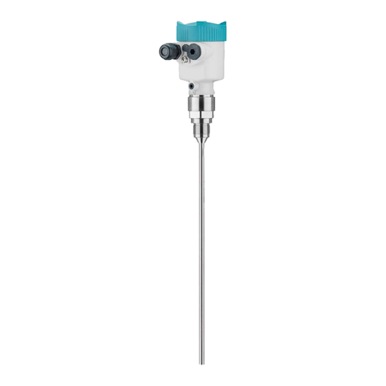
Guided wave radar
4...20 ma/hart - two-wire
rod and cable probe
with sil qualification
Hide thumbs
Also See for SITRANS LG250:
- Operating instructions manual (92 pages) ,
- Operating instructions manual (76 pages) ,
- Operating instructions manual (88 pages)

Related Manuals for Siemens SITRANS LG250


Summary of Contents for Siemens SITRANS LG250
- Page 1 Guided Wave Radar SITRANS LG250 4 … 20 mA/HART - two-wire Rod and cable probe With SIL qualification Operating Instructions • 03/2014...
- Page 2 SITRANS LG250 - Operating Instructions PBD-51041388...
-
Page 3: Table Of Contents
Adjustment system ......................33 Parameter adjustment ....................35 Saving the parameter adjustment data ................56 Setup with PACTware Connect the PC ......................57 Parameter adjustment with PACTware ................58 Saving the parameter adjustment data ................59 PBD-51041388 SITRANS LG250 - Operating Instructions... - Page 4 12.1 Technical data ........................ 73 12.2 Dimensions ........................84 Safety instructions for Ex areas Please note the Ex-specific safety information for installation and op- eration in Ex areas. These safety instructions are part of the operating instructions manual and come with the Ex-approved instruments. Editing status: 2014-03-17 SITRANS LG250 - Operating Instructions PBD-51041388...
-
Page 5: About This Document
List The dot set in front indicates a list with no implied sequence. → Action This arrow indicates a single action. Sequence of actions Numbers set in front indicate successive steps in a procedure. PBD-51041388 SITRANS LG250 - Operating Instructions... -
Page 6: For Your Safety
During work on and with the device the required personal protective equipment must always be worn. Appropriate use SITRANS LG250 is a sensor for continuous level measurement. You can find detailed information about the area of application in chapter "Product description". Operational reliability is ensured only if the instrument is properly used according to the specifications in the operating instructions manual as well as possible supplementary instructions. -
Page 7: Sil Qualification According To Iec 61508
That is why we have introduced an environment management system with the goal of continuously improving company environmental pro- tection. The environment management system is certified according to DIN EN ISO 14001. Please help us fulfill this obligation by observing the environmental instructions in this manual: • Chapter "Packaging, transport and storage" • Chapter "Disposal" PBD-51041388 SITRANS LG250 - Operating Instructions... -
Page 8: Product Description
• Standard electronics: Type FX80H.-SIL Scope of delivery The scope of delivery encompasses: • Sensor • Documentation – This operating instructions manual SITRANS LG250 - Operating Instructions PBD-51041388... -
Page 9: Principle Of Operation
– Ex-specific "Safety instructions" (with Ex versions) – if necessary, further certificates Principle of operation Application area The SITRANS LG250 is a level sensor with cable or rod probe for continuous level or interface measurement, suitable for applications in liquids. Due to the qualification up to SIL2 or homogeneous redundant up to SIL3 (IEC 61508) the SITRANS LG250 is suitable for the use in safety-instrumented systems (SIS). - Page 10 Example: upper medium dielectric constant 2, lower medium at least dielectric constant 12. Gas phase (L3) • Air or gas mixture • Gas phase - dependent on the application, gas pahse does not always exist (d2 = 0) SITRANS LG250 - Operating Instructions PBD-51041388...
-
Page 11: Packaging, Transport And Storage
Ex-d double chamber housing. It is suitable for measured value indication and adjustment of sensors and is connected to the sensor with a four-wire standard cable up to 50 m (164 ft) long. PBD-51041388 SITRANS LG250 - Operating Instructions... - Page 12 Curved segments: 100 x 100 mm (3.94 … 3.94 in) You can find further information in the operating instructions manual "Rod extension SITRANS series LG". Spacer If you mount the SITRANS LG250 in a bypass tube or standpipe, you have to avoid contact to the bypass tube by using a spacer at the probe end. You can find additional information in the operating instructions manual "Centering".
-
Page 13: Mounting
Keep in mind that measurement all the way down to the tip of the probe may not be pos- sible. The exact value of the min. distance (lower dead band) is stated in chapter "Technical data". PBD-51041388 SITRANS LG250 - Operating Instructions... - Page 14 EN 61326: class A). In this case, use a probe with coaxial version. Fig. 5: Installation in non-metallic vessel Flange Metal sheet If possible, avoid sockets. Mount the sensor flush with the vessel top. Socket If this is not possible, use short sockets with small diameter. SITRANS LG250 - Operating Instructions PBD-51041388...
- Page 15 Fig. 7: Socket must be installed flush Unfavourable installation 2 Socket flush - optimum installation Welding work Before beginning the welding work, remove the electronics module from the sensor. By doing this, you avoid damage to the electronics through inductive coupling. Inflowing medium Do not mount the instruments in or above the filling stream. Make sure that you detect the product surface, not the inflowing product. PBD-51041388 SITRANS LG250 - Operating Instructions...
- Page 16 Microwaves can penetrate many plastics. This is why plastic tubes are problematic for measurement applications. If durability is no problem, we recommend the use of uncoated metal standpipes. SITRANS LG250 - Operating Instructions PBD-51041388...
- Page 17 When the SITRANS LG250 is used in bypass tubes, contact with the tube wall must be avoided. We recommend for this purpose a cable probe with centering weight. Caution: When mounting, make sure that the cable is straight over its entire length.
- Page 18 This allows you to measure the total level range of the medium in the standpipe. When designing the standpipe, keep the upper blocking distance of the probe in mind and plan the length above the upper lateral filling opening accordingly. SITRANS LG250 - Operating Instructions PBD-51041388...
- Page 19 If durability is no problem, we recommend the use of uncoated metal standpipes. When the SITRANS LG250 is used in standpipes, contact with the tube wall must be avoided. We recommend for this purpose a cable probe with centering weight.
- Page 20 Rod extension In case of difficult installation conditions, for example in a socket, the probe can be adapted respectively with a rod extension. Let the probe length determine automatically by the instrument to compensate the resulting running time changes. You can find further information in the supplementary instructions of the rod extension. SITRANS LG250 - Operating Instructions PBD-51041388...
-
Page 21: Connecting To Power Supply
(e. g. 1 nF, 1500 V). The low-frequency potential equalisation currents are thus suppressed, but the protective effect against high frequency interfer- ence signals remains. Warning: Significant potential differences exist inside galvanization plants as well as on vessels with cathodic corrosion protection. Considerable PBD-51041388 SITRANS LG250 - Operating Instructions... -
Page 22: Connection
4. Remove approx. 10 cm (4 in) of the cable mantle, strip approx. 1 cm (0.4 in) of insulation from the ends of the individual wires 5. Insert the cable into the sensor through the cable entry Fig. 12: Connection steps 5 and 6 SITRANS LG250 - Operating Instructions PBD-51041388... -
Page 23: Wiring Plan, Single Chamber Housing
For display and adjustment module or interface adapter For external display and adjustment unit Ground terminal for connection of the cable screen Wiring plan, double chamber housing The following illustrations apply to the non-Ex as well as to the Ex-ia version. PBD-51041388 SITRANS LG250 - Operating Instructions... -
Page 24: Double Chamber Housing With Dis-Adapt
Ground terminal for connection of the cable screen Double chamber housing with DIS-ADAPT Plug M12 x 1 for VE- GADIS 61 Fig. 16: Top view of the plug connector Pin 1 Pin 2 Pin 3 Pin 4 SITRANS LG250 - Operating Instructions PBD-51041388... -
Page 25: Wiring Plan, Ex-D-Ia Double Chamber Housing
For display and adjustment module or interface adapter Internal connection to the plug connector for external display and adjust- ment unit (optional) Terminal compartment 4...20mA Fig. 18: Connection compartment with double chamber housing Ex d Voltage supply/Signal output Ground terminal for connection of the cable screen PBD-51041388 SITRANS LG250 - Operating Instructions... -
Page 26: Supplementary Electronics
Additional current output (II) - Voltage supply and signal output (without HART) Ground terminal for connection of the cable screen Switch-on phase After connecting the instrument to power supply or after a voltage recurrence, the instrument carries out a self-check for approx. 30 s: SITRANS LG250 - Operating Instructions PBD-51041388... - Page 27 As soon as a plausible measured value is found, the corresponding current is outputted to the signal cable. The value corresponds to the actual level as well as the settings already carried out, e.g. factory setting. PBD-51041388 SITRANS LG250 - Operating Instructions...
-
Page 28: Functional Safety (Sil)
Application area The instrument can be used for point level detection or level measure- ment of liquids and bulk solids in safety-instrumented systems (SIS) according to IEC 61508 and IEC 61511. Take note of the specifica- tions in the Safety Manual. SITRANS LG250 - Operating Instructions PBD-51041388... -
Page 29: Safety Concept Of The Parameterization
Unsafe device If adjustment is enabled, the safety function must be considered status as unreliable. This applies until the parameterisation is terminated correctly. If necessary, other measures must be taken to maintain the safety function. PBD-51041388 SITRANS LG250 - Operating Instructions... -
Page 30: Setup Process
Set up the SITRANS LG250 according to the specification in this operating instructions and the Safety Manual. Setup - Function test When locking the adjustment, the instrument checks the data of the measurement loop and decides on the basis of the evaluation results if a function test is required. SITRANS LG250 - Operating Instructions PBD-51041388... - Page 31 If you have to interrupt the function, you can leave the SITRANS LG250 in the respective situation. As long as SITRANS LG250 is powered, the display and adjustment module remains in the currently set adjustment menu. To interrupt the function test, you have to push the button "ESC".
- Page 32 Then you carry out a comparison of two character strings. You must confirm that the character strings are identical. This is used to check the character presentation. Then you confirm that the serial number of your instrument has been carried over correctly. This is used to check device communication. Then, all modified parameters that have to be confirmed are listed. After this process is terminated, the safety function is again ensured. SITRANS LG250 - Operating Instructions PBD-51041388...
-
Page 33: Set Up With The Display And Adjustment Module
Note: If you intend to retrofit the instrument with a display and adjustment module for continuous measured value indication, a higher cover with an inspection glass is required. Adjustment system Fig. 22: Display and adjustment elements 1 LC display Adjustment keys • Key functions [OK] key: PBD-51041388 SITRANS LG250 - Operating Instructions... - Page 34 [OK] will not be saved. Switch-on phase After switching on, the SITRANS LG250 carries out a short self-test where the device software is checked. The output signal transmits a fault signal during the switch-on phase. The following information is displayed on the display and adjustment module during the startup procedure: •...
-
Page 35: Parameter Adjustment
The following submenu points are available: The submenu points described below. Operating sequence A parameter change with SIL qualified instruments must always be carried out as follows. • Unlock adjustment • Change parameters • Lock adjustment and verify modified parameters This ensures that all modified parameters have been deliberately changed. Unlock adjustment The instrument is shipped in locked condition. PBD-51041388 SITRANS LG250 - Operating Instructions... - Page 36 When choosing "No", you can enter the probe length manually. Setup - Application - Type In this menu item you can select which type of medium you want to of medium measure. You can choose between liquid or bulk solid. SITRANS LG250 - Operating Instructions PBD-51041388...
- Page 37 "Application". In this menu item you can enter if there is a superimposed gas phase in your application. Only set the function to "Yes", if the gas phase is permanently pre- sent. PBD-51041388 SITRANS LG250 - Operating Instructions...
- Page 38 In this menu item you can enter the min. adjustment for the level. With Level interface measurement this is the minimum total level. Adjust the requested percentage value with [+] and store with [OK]. SITRANS LG250 - Operating Instructions PBD-51041388...
- Page 39 (accept adjustment of the level measure- ment), the current setting will be displayed. If you have selected "No", you can enter the adjustment for the inter- face measurement separately. PBD-51041388 SITRANS LG250 - Operating Instructions...
- Page 40 For the socket correction you have to enter the height of the socket above the upper edge of the vessel. If the socket is lower than the up- per edge of the vessel, this value can also be negative. SITRANS LG250 - Operating Instructions PBD-51041388...
- Page 41 Since scaling is very extensive, scaling of the level value was divided into two menu items. Setup - Scaling Level 1 In menu item "Level 1" you define the scaling variable and the scaling unit for the level value on the display, e.g. volume in l. PBD-51041388 SITRANS LG250 - Operating Instructions...
- Page 42 0 % and 100 %. In menu item "Current output, variable" you specify which measured Setup - Current output Size variable the current output refers to. SITRANS LG250 - Operating Instructions PBD-51041388...
- Page 43 (SIL). The procedure corresponds to the previous settings of the standard current output. See "Setup - Current output". Setup - HART variables Since the HART variables are very extensive, the indication was divided into two menu items. PBD-51041388 SITRANS LG250 - Operating Instructions...
- Page 44 Proceed as follows: Enter the actual distance from the sensor to the product surface. All interfering signals in this section are detected by the sensor and stored. SITRANS LG250 - Operating Instructions PBD-51041388...
- Page 45 This is used to check device communication. In the next step, the instrument checks the data of the measurement and decides by means of the evaluation results if a functions test PBD-51041388 SITRANS LG250 - Operating Instructions...
- Page 46 If you have to interrupt the function, you can leave the SITRANS LG250 in the respective situation. As long as SITRANS LG250 is powered, the display and adjustment module remains in the currently set adjustment menu. To interrupt the function test, you have to push the button "ESC".
- Page 47 If you have to interrupt the function test, you can leave the display and adjustment module of SITRANS LG250 in its current state. As long as SITRANS LG250 is powered, the display and adjustment module remains in the currently set adjustment menu.
- Page 48 Values > 90 % indicate reliable measurement. If you have selected interface measurement under the menu item "Setup - Application", the peak values of the interface measurement are displayed in addition to the peak values of the level measurement. SITRANS LG250 - Operating Instructions PBD-51041388...
- Page 49 In this menu item you can simulate measured values via the current output. This allows the signal path to be tested, e.g. through down- stream indicating instruments or the input card of the control system. PBD-51041388 SITRANS LG250 - Operating Instructions...
- Page 50 Diagnosis - Proof test With the function "Proof test", the function of the instrument can be checked on a recurring basis. SITRANS LG250 - Operating Instructions PBD-51041388...
- Page 51 The following tables show the default values of the instrument. De- pending on the instrument version or application, all menu items may not be available or some may be differently assigned. The menu items in bold are safety-relevant in terms of the functional safety according to IEC 61508 (Edition 2) SIL. PBD-51041388 SITRANS LG250 - Operating Instructions...
- Page 52 Scaling level - 100 % correspond to Scaling level - 0 % correspond to Accept scaling of the level measurement Scaling variable - Interface Volume Scaling unit - Interface Litres Scaling format - Interface Without decimal positions SITRANS LG250 - Operating Instructions PBD-51041388...
- Page 53 Status signals - Maintenance Switched on Device memory - Echo curve memory Stopped Device memory - Measured value memory Started Device memory - Measured value memory - Distance level, percentage value Measured values level, reliability level, electronics temperature Device memory - Measured value memory - Re- 3 min. cording in time interval Device memory - Measured value memory - Re- 15 % cording with measured value difference PBD-51041388 SITRANS LG250 - Operating Instructions...
- Page 54 In this menu item you can select the type and size of your probe from Probe type a list of all possible probes. This is necessary to adapt the electronics optimally to the probe. SITRANS LG250 - Operating Instructions PBD-51041388...
- Page 55 PC. Info - Sensor character- In this menu item, the features of the sensor such as approval, pro- istics cess fitting, seal, measuring range, electronics, housing and others are displayed. PBD-51041388 SITRANS LG250 - Operating Instructions...
-
Page 56: Saving The Parameter Adjustment Data
If it is necessary to exchange a sensor, the display and adjustment module is inserted into the replacement instrument and the data are likewise written into the sensor via the menu item "Copy sensor data". SITRANS LG250 - Operating Instructions PBD-51041388... -
Page 57: Setup With Pactware
Setup with PACTware Connect the PC Via the interface adapter directly on the sensor Fig. 24: Connection of the PC directly to the sensor via the interface adapter 1 USB cable to the PC Interface adapter Sensor Connection via HART Fig. 25: Connecting the PC via HART to the signal cable Sensor 2 HART resistance 250 Ω (optional depending on processing) Adapter cable for HART modem 4 Processing system/PLC/Voltage supply HART modem PBD-51041388 SITRANS LG250 - Operating Instructions... -
Page 58: Parameter Adjustment With Pactware
You can also save measured value and echo curves in the DTM. Furthermore a tank calculation program as well as a multiviewer for indication and analysis of the saved measured value and echo curves are available. The supplied DVD includes the respective device DTM. How- ever, you can also download the DTM from our homepage www.siemens.com/sitranslg. SITRANS LG250 - Operating Instructions PBD-51041388... -
Page 59: Saving The Parameter Adjustment Data
Saving the parameter adjustment data We recommend documenting or saving the parameter adjustment data via PACTware. That way the data are available for multiple use or service purposes. PBD-51041388 SITRANS LG250 - Operating Instructions... -
Page 60: Set Up With Other Systems
Device descriptions as Enhanced Device Description (EDD) are available for DD adjustment programs such as, for example, AMS™ and PDM. Communicator 375, 475 Device descriptions for the instrument are available as DD or EDD for parameter adjustment with the Field Communicator 375 or 475. A free-of-charge download of these files is available via Internet. Move via www.vega.com and "Downloads" to "Software". SITRANS LG250 - Operating Instructions PBD-51041388... -
Page 61: Diagnostics And Servicing
The requested values and recording conditions are set via a PC with PACTware/DTM or the control system with EDD. Data are thus read out and also reset. The instrument also has an integrated event memory with time stamp. Event memory Up to 500 events are automatically stored in the sensor and are delete protected. Each entry contains date/time, event time, event description and value. PBD-51041388 SITRANS LG250 - Operating Instructions... -
Page 62: Status Messages
(for example due to buildup). This status message is always inactive and can be activated via DTM and EDD. The error codes are dispayed via the indicating and adjustment module as well as DTM and EDD in the control system. Additional in- formation on error statstics is displayed in the menu Diagnosis under SITRANS LG250 - Operating Instructions PBD-51041388... - Page 63 4-wire power supply unit F125 – Temperature of the elec- – Check ambient temperature tronics in the non-specified – Isolate electronics Impermissi- range ble electronics – Use instrument with higher temperature temperature range PBD-51041388 SITRANS LG250 - Operating Instructions...
- Page 64 – Parameter verification was – Finish parameter verifica- interrupted tion Parameter verification Out of specification The following table shows the error codes and text messages in the status message "Out of specification" and provides information on causes as well as corrective measures. SITRANS LG250 - Operating Instructions PBD-51041388...
- Page 65 – Measurement certainty is – Check installation and too low for a reliable meas- process conditions Meas. reliabil- urement – Clean or exchange process ity too low – Process component or component or probe probe contaminated or defective PBD-51041388 SITRANS LG250 - Operating Instructions...
-
Page 66: Rectify Faults
"Connection steps" and if necessary, correct according to chap- ter "Wiring plan" Voltage supply Check cables for breaks; repair if nec- missing essary Operating voltage Check, adapt if necessary too low or load re- sistance too high SITRANS LG250 - Operating Instructions PBD-51041388... - Page 67 – Amplitude or position of a – Determine the reason for the false signal has changed (e.g. changed false signals, carry out buildup); false signal suppres- false signal suppression, e.g. sion no longer matches with buildup PBD-51041388 SITRANS LG250 - Operating Instructions...
-
Page 68: Exchanging The Electronics Module
10.5 Exchanging the electronics module If the electronics module is defective, it can be replaced by the user. With SIL qualified instrument, only a respective electronics module with SIL qualification must be used. In Ex applications, only instruments and electronics modules with ap- propriate Ex approval may be used. SITRANS LG250 - Operating Instructions PBD-51041388... -
Page 69: Exchanging The Cable/Rod
6. Exert counterforce with the second fork spanner and tighten the rod or cable on the flat surfaces with the following torque. Rod ø 8, cable ø 2 and 4: 6 Nm (4.43 lbf ft) Rod ø 12: 10 Nm (7.37 lbf ft) PBD-51041388 SITRANS LG250 - Operating Instructions... - Page 70 6. Cable with gravity weight: Shift the cable according to the drawing into the gravity weight 7. Cable with gravity weight: Fasten cable with the pins, torque 7 Nm (5.16 lbf ft) Cable with centering weight: Fasten cable with the pins, torque 7 Nm (5.16 lbf ft) and fix the clamping part on the centering weight. SITRANS LG250 - Operating Instructions PBD-51041388...
-
Page 71: Software Update
Instruments with approvals can be bound to certain software versions. Therefore make sure that the approval is still effective after a software update is carried out. You can find detailed information in the download area on our home- page: www.siemens.com/sitranslg. 10.8 How to proceed if a repair is necessary If it is necessary to repair the instrument, please contact Sie- mens Milltronics Process Instruments. You find the locations on "www.siemens.com/sitranslg". PBD-51041388 SITRANS LG250 - Operating Instructions... -
Page 72: Dismount
Pass the instrument directly on to a spe- cialised recycling company and do not use the municipal collecting points. These may be used only for privately used products according to the WEEE directive. SITRANS LG250 - Operating Instructions PBD-51041388... -
Page 73: Supplement
Ʋ Supporting material 316L Ʋ Glass potting Borosilicate glass GPC 540 Ʋ Contacts Alloy C22 (2.4602) Ʋ Helium leak rate < 10 mbar l/s Ʋ Pressure resistance See process pressure of the sensor Ohmic contact Between ground terminal, process fitting and probe PBD-51041388 SITRANS LG250 - Operating Instructions... - Page 74 Ʋ Cable: ø 2 mm (0.079 in) 6 Nm (4.43 lbf ft) Ʋ Cable: ø 4 mm (0.157 in) 6 Nm (4.43 lbf ft) Ʋ Rod: ø 8 mm (0.315 in) 6 Nm (4.43 lbf ft) SITRANS LG250 - Operating Instructions PBD-51041388...
- Page 75 ε ≥ 1.6 Ʋ Rod probes ε ≥ 1.6 Fig. 38: Measuring ranges - SITRANS LG250 Reference plane Probe length L Measuring range (default setting refers to the measuring range in water) Upper dead band (see diagrams under Accuracy - grey section)
- Page 76 (+12.5 … +15.4 psig) Installation reference conditions Ʋ Min. distance to internal installations > 500 mm (19.69 in) The output values can be assigned individually The indication values can be assigned individually The indication values can be assigned individually SITRANS LG250 - Operating Instructions PBD-51041388...
- Page 77 (3.15 (11.811 " " (0.787 ") Fig. 39: Deviation SITRANS LG250 in rod version in water Dead band - no measurement possible in this area Probe length With interface measurement = 2.0 Depending on the installation conditions, deviations can occur which can be rectified by adapting the adjust- ment or changing the measured value offset in the DTM service mode The dead bands can be optimized via a false signal suppression.
- Page 78 (5.906 (11.811 " ") (2.756 ") 0,05 m (1.97 ") Fig. 40: Deviation SITRANS LG250 in rod version in oil Dead band - no measurement possible in this area Probe length 15 mm (0.591 ") 2 mm (0.079 ") -2 mm (-0.079...
- Page 79 " ") (1.969 ") 0,08 m (3.15 ") Fig. 42: Deviation SITRANS LG250 in cable version ø 2 mm (0.079 in), in oil Dead band - no measurement possible in this area Probe length 20 mm (0.787 " 15 mm (0.591...
-
Page 80: Ambient Conditions
-40 … +80 °C (-40 … +176 °F) ture Also for the additional current output (optional) Time span after a sudden measuring distance change by max. 0.5 m in liquid applications, max 2 m with bulk solids applications, until the output signal has taken for the first time 90 % of the final value (IEC 61298-2). SITRANS LG250 - Operating Instructions PBD-51041388... - Page 81 Fig. 44: Ambient temperature - process temperature, standard version Ambient temperature Process temperature (depending on the seal material) Maximum permissible temperature - standard Limited temperature range - plastic housing and stainless steel housing, electropolished PBD-51041388 SITRANS LG250 - Operating Instructions...
- Page 82 Display and adjustment module Voltage supply and data transmission through the sensor Indication LC display in dot matrix Adjustment elements 4 keys Protection rating Ʋ unassembled IP 20 Ʋ mounted into the sensor without cover IP 40 SITRANS LG250 - Operating Instructions PBD-51041388...
- Page 83 Ʋ Example - Non-Ex instrument with (24 V - 9.6 V)/0.0215 A = 670 Ω = 24 V DC Electrical protective measures Protection rating Housing material Version IP-protection class NEMA protection Plastic Single chamber IP 66/IP 67 NEMA 4X Double chamber IP 66/IP 67 NEMA 4X PBD-51041388 SITRANS LG250 - Operating Instructions...
-
Page 84: Dimensions
Fig. 46: Housing versions with protection rating IP 66/IP 68 (0.2 bar) - with integrated display and adjustment module the housing is 9 mm/0.35 in higher Single chamber version Double chamber version IEC 61010-1 IEC 61010-1 SITRANS LG250 - Operating Instructions PBD-51041388... - Page 85 Fig. 48: Housing versions with protection rating IP 66/IP 68 (0.2 bar) - with integrated display and adjustment module the housing is 9 mm/0.35 in higher Single chamber version, electropolished Single chamber version, precision casting Double chamber version, precision casting PBD-51041388 SITRANS LG250 - Operating Instructions...
- Page 86 ø 20 mm ø 20 mm ø 20 mm (0.79") (0.79") (0.79") Fig. 49: SITRANS LG250, threaded version with gravity weight (all gravity weights with thread M8 for eye-bolt) Sensor length, see chapter "Technical data" SITRANS LG250 - Operating Instructions PBD-51041388...
- Page 87 G1½, 1½ NPT ø 4 mm (0.16") ø 2 mm (0.08") Fig. 50: SITRANS LG250, threaded version Sensor length, see chapter "Technical data" ø 40 mm (1.57 in) ø 45 mm (1.77 in) ø 75 mm (2.95 in) ø 95 mm (3.74 in) Cable version ø 2 mm (0.079 in) with centering weight (see supplementary instructions "Centering")
- Page 88 G1½, 1½ NPT ø 8 mm ø 12¨mm (0.32") (0.47") Fig. 51: SITRANS LG250, threaded version Sensor length, see chapter "Technical data" Rod version ø 8 mm (0.315 in) Rod version ø 12 mm (0.472 in) SITRANS LG250 - Operating Instructions...
- Page 89 12.3 Trademark All the brands as well as trade and company names used are property of their lawful proprietor/ originator. PBD-51041388 SITRANS LG250 - Operating Instructions...
-
Page 90: Sitrans Lg250 - Operating Instructions Pbd
Electronics compartment with double chamber Potential equalisation 21 housing 24 Probe length 36 Event memory 61 Probe type 54 Proof test 50 Factory calibration date 55 False signal suppression 44 Read out info 55 SITRANS LG250 - Operating Instructions PBD-51041388... - Page 91 Sensor characteristics 55 Sensor status 48 Shielding 21 SIL 28 Simulation 49 Special parameters 55 Status messages 62 Storage 11 Type label 8 Type of medium 36 Units 36 Unlock adjustment 45 Verify parameter 32 Voltage supply 21 PBD-51041388 SITRANS LG250 - Operating Instructions...
- Page 92 For more information www.siemens.com/level www.siemens.com/weighing Siemens AG Subject to change without prior notice Industry sector PBD-51041388 Rev. 1.0 1954 Technology Drive P.O. Box 4225 © Siemens AG 2015 Peterborough. ON Canada K9J7B1 email: techpubs.smpi@siemens.com Printed in Canada www.siemens.com/processautomation...
Need help?
Do you have a question about the SITRANS LG250 and is the answer not in the manual?
Questions and answers