Table of Contents
Advertisement
Quick Links
Advertisement
Table of Contents

Related Manuals for ICRealtime HD Pinhole


Summary of Contents for ICRealtime HD Pinhole
- Page 1 HD Pinhole Network Camera User’s Manual Version 1.0.0...
- Page 2 Welcome Thank you for purchasing our network camera! This user’s manual is designed to be a reference tool for your system. Please read the following safeguard and warnings carefully before you use this series product! Please keep this user’s manual well for future reference!
-
Page 3: Important Safeguards And Warnings
Important Safeguards and Warnings 1.Electrical safety All installation and operation here should conform to your local electrical safety codes. The power shall conform to the requirement in the SELV (Safety Extra Low Voltage) and the Limited power source is rated 12V DC or 24V AC in the IEC60950-1. (Refer to general introduction) Please note: Do not connect two power supplying sources to the device at the same time;... - Page 4 Do not touch the CCD (CMOS) optic component. You can use the blower to clean the dust on the lens surface. Always use the dry soft cloth to clean the device. If there is too much dust, please use the water to dilute the mild detergent first and then use it to clean the device.
-
Page 5: Table Of Contents
Table of Contents General Introduction ........................1 Overview ........................1 Features ......................... 1 Specifications ........................ 2 1.3.1 Performance ......................2 Device Framework ........................4 Port Name........................4 Dimension ........................5 Bidirectional Talk ......................7 2.3.1 Device-end to PC-end ..................7 2.3.2 PC-end to the Device-end .................. -
Page 6: General Introduction
1 General Introduction 1.1 Overview This series network camera integrates the traditional camera and network video technology. It adopts video data collection, transmission together. It can connect to the network directly without any auxiliary device. This series network camera uses standard H.264 video compression technology, which maximally guarantees the video quality. -
Page 7: Specifications
Support digital WDR. Support video watermark function to avoid vicious video modification. Support dual bit streams, ACF. 1.3 Specifications 1.3.1 Performance Please refer to the following sheet for network camera performance specification. Model ICIP T801 Parameter Main Processor High performance DSP Embedded LINUX System... - Page 8 Audio Compression G.711a/G.711Mu/PCM Standard 396 (18*22) detection zones; sensitivity level ranges from 0 to 100; Motion Detect area threshold ranges from 0 to 100. Alarm Port 1-ch input, 1-ch output Record Priority Manual>External alarm>Video detect>Schedule Storage Support Micro SD card storage (support 64GB); FTP remote server Management storage.
-
Page 9: Device Framework
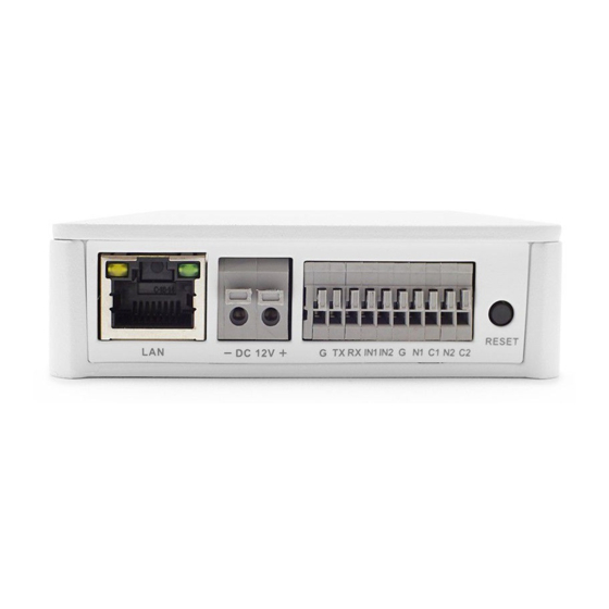
2 Device Framework 2.1 Port Name Note: The framework figures in this chapter are just for reference, there is some minor difference between the appearance of products and the corresponding figures, so please refer to the actual products. You can refer to the following figures for port information. -
Page 10: Dimension
Port Port Name Connector Function Note Sensor Sensor port Connect front end Sensor board, get image data. SENSOR board Ethernet Network port Connect standard Ethernet cable port Power input DC12V Power port, input DC12 V or POE power supply. port I/O port Connect I/O port. - Page 11 Figure 2-3 Figure 2-4 Figure 2-5...
-
Page 12: Bidirectional Talk
2.3 Bidirectional Talk 2.3.1 Device-end to PC-end Device Connection Please connect the speaker or the MIC to the audio input port of the device. Then connect the earphone to the audio output port of the PC. Login the Web and then click the Talk button to enable the bidirectional talk function. You can see the button becomes orange after you enabled the bidirectional talk function. -
Page 13: Device Installation
3 Device Installation Important Please make sure the installation surface can min support the 3X weight of the camera and the bracket. Figure 3-1 Please see Figure 3-1. Step 1 Stick installation position map to designated surface where you will install the device Step 2 Dig a hole according to position of hole on installation position map. -
Page 14: Quick Configuration Tool
4 Quick Configuration Tool 4.1 Overview Quick configuration tool can search current IP address, modify IP address. At the same time, you can use it to upgrade the device. Please note the tool only applies to the IP addresses in the same segment. 4.2 Operation Double click the “ConfigTools.exe”... - Page 15 Figure 4-2 Login prompt After you logged in, the configuration tool main interface is shown as below. See Figure 4-3. Figure 4-3 Main interface For detailed information and operation instruction of the quick configuration tool, please refer to the Quick Configuration Tool User’s Manual included in the resources CD.
-
Page 16: Web Operation
5 Web Operation This series network camera products support the Web access and management via PC. Web includes several modules: Monitor channel preview, system configuration, alarm and etc. 5.1 Network Connection Please follow the steps listed below for network connection. ... - Page 17 Figure 5- 2 Web login After you successfully logged in, please install WEB plug-in unit. Please refer to the Web Operation Manual included in the resource CD for detailed operation instruction. See Figure 5- 3. Figure 5- 3 Web monitoring window...
-
Page 18: Faq
6 FAQ I can not boot up Please click RESET button for at least five seconds to restore the device or factory default setup. operate properly. The water leakage The unauthorized front or rear cap remove many result in water occurred. -
Page 19: Appendix Toxic Or Hazardous Materials Or Elements
Appendix Toxic or Hazardous Materials or Elements Toxic or Hazardous Materials or Elements Component Name Cr VI PBDE Circuit Board ○ ○ ○ ○ ○ ○ Component ○ ○ ○ ○ ○ ○ Device Case ○ ○ ○ ○ ○ ○...
Need help?
Do you have a question about the HD Pinhole and is the answer not in the manual?
Questions and answers