Table of Contents
Advertisement
Quick Links
Advertisement
Table of Contents

Related Manuals for Whip Mix P.D.Q.


Summary of Contents for Whip Mix P.D.Q.
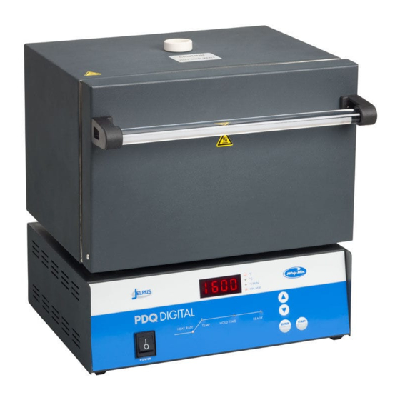
- Page 1 P . D.Q. Automatic Burnout Furnaces 115 and 230-volt Models OPERATOR’S MANUAL...
-
Page 2: Table Of Contents
TABLE OF CONTENTS Introduction . . . . . . . . . . . . . . . . . . . . . . . . . . . . . . . . . . . . . . . . . . . . . . . . . . . . . . . . . . . . 3 Warranty . -
Page 3: Introduction
. Since the interior of the unit may contain high voltage and dangerous components, failure to heed this warning may result in equipment damage, personal injury and/or death . Please call Whip Mix between 8:00 a .m . and 5:00 p .m . (EST) for service information toll free 800-626-5651 . -
Page 4: Specifications
SPECIFICATIONS PDQ-D Medium PDQ-D Large Electrical 115V 50/60Hz 1075W 115V 50/60Hz 1392W 230V 50/60Hz 1280W 230V 50/60Hz 1890W Capacity 8–1 3/4” rings or 2–3” rings 15–1 3/4” rings or 5–1 3/4” rings and 3–3” rings Overall 10 .7”W x 10 .6”D x 15 .0”H 14 .4”W x 11 .0”D x 15 .0”H Dimensions (27 .2cm x 26 .9cm x 38 .1cm) -
Page 5: Key Parts Identification & Explanation
KEY PARTS IDENTIFICATION AND EXPLANATION FRONT PANEL (Figure 1) DISPLAY DESCRIPTION 1 . START / STOP Press to start or stop a program . Press to increase a number . The longer the button is pressed, the faster the numbers change . Press to decrease a number . - Page 6 KEY PARTS IDENTIFICATION AND EXPLANATION Vent Tube Keep clear 6” zone around Vent Tube Heating Chamber ° F ° C ° / M IN H H :MM DIGITAL HEAT RATE TEMP HO LD TIM E REA DY ENTER START REVIEW STOP P O W E R Front...
- Page 7 KEY PARTS IDENTIFICATION AND EXPLANATION LOWER BACK PANEL (Figure 2) DISPLAY DESCRIPTION 1 . Power Cord AC power cords are provided to correspond to receptacles that are available in a specific country . 2 . Circuit Breaker Protects circuitry from electrical overload . •...
-
Page 8: Installation
INSTALLATION UNPACK AND SET-UP 1 . Unpack the contents of the box . Remove the following materials: A . Vent Tube – Remove from bubble wrap and insert in hole on top of furnace . B . Calibration Table Kit – Remove plastic bag containing two tablets and save for future use . C . -
Page 9: Operation
OPERATION PROGRAM AND OPERATE (Figure 1) 1 . Turn the power switch on . 2 . Press ENTER / REVIEW . HEAT RATE light turns on . Enter to select the heat rate required from 1°F – 30°F / min (1°C – 17°C / min) or “FULL” for the maximum heat rate . 3 . -
Page 10: Sample Programs
OPERATION SAMPLE PROGRAM HEAT RATE TEMP HOLD TIME 1:00 10°F (6°C) 1600°F (871°C) To start immediately, press START / STOP . -
Page 11: Error Codes
ERROR CODES NOTE: “Beeps” occur when the Error Code appears on the Main Display ERROR DESCRIPTION PROBABLE CAUSE CODE OPEN Occurs if the thermocouple is open or the connecting wire(s) are broken Er-1 THERMOCOUPLE or disconnected from the terminal board . Occurs when the temperature on the display is outside the allowable range Er 2 TABLET... -
Page 12: Service
For help with operating or servicing your Jelrus equipment, please call Whip Mix any time between 8:00am and 5:00pm Eastern time. Toll Free: 1–800–626–5651... - Page 13 SERVICE 5 . When the tablet begins to melt or liquefy at the edges, immediately press and hold . Then press ENTER / REVIEW . Your PDQ is now calibrated . Three “beeps” sound and “CAL” appears on the main display . POWER FAILURE 1 .
-
Page 14: Field Service
FIELD SERVICE REPLACEMENT OF HEATING PLATES Place the new plates in the chamber, if back plates are Turn off the power to the oven, unplug the power cord, remove trays from the muffle chamber and insure that being replaced as well they must be installed first, also insure that the wires are bent up so they will slide into the oven is cool . - Page 15 Figure 4 Figure 4 PDQ-D WITH UPPER REAR PANEL REMOVED PDQ-D WITH UPPER REAR PANEL REMOVED Jumper Rear Insulating Panel Heating Plate Wire Thermocouple Power Terminal Ceramic Insulating Bushing Heater (Power) Leads PDQ-D Medium (all voltage models) Jumper Rear Insulating Panel Heating Plate Wire Thermocouple Power Terminal...
-
Page 16: Replacement Of Main Pc Board
FIELD SERVICE REPLACEMENT OF THE MAIN PC BOARD Part numbers can be found on last page(s) of Manual . 1 . Remove the bottom panel . 2 . Note and record the color and location of each wire on the thermocouple terminals located on the Main PC Board. - Page 17 Figure 5 PDQ-D WIRING DIAGRAM...
-
Page 18: Replacement Of Thermocouple Assembly
FIELD SERVICE REPLACEMENT INSTRUCTIONS: 15295 JELRUS THERMOCOUPLE For assistance call 1-800-626-5651 or write to: tops@whipmix .com CAUTION! TO PREVENT INJURY, ALWAYS TURN POWER OFF AND DISCONNECT THE OVEN’S POWER CORD BEFORE PERFORMING SERVICE. VERIFY THAT UNIT IS COOL TO THE TOUCH. Front View Large Rear View Medium Rear View Large... -
Page 19: Replacement Of The Relay
FIELD SERVICE REPLACEMENT OF THE SSR (Solid State Relay) (PN 96225) 1 . Remove the lower bottom panel (Figure 2, Page 7) . 2 . Note and record the color and location of each of the four wires on the SSR terminals (Figure 5, Page 17) . Remove each of the four wires by pulling straight up on the connecter . - Page 20 SPARE PARTS LIST PARTS FOR PDQ-D Medium Part No. Description 115V 230V Power Cord Kit-Japan & U .S . 26202 Power Cord Kit-Europe 23203 Power Cord Kit-UK 23202 Power Cord Kit-Italy 23205 NEW-Main PC Board 15298 15299 Heater Jumper 33130 33130 Ceramic Front Section 15292...
-
Page 21: Spare Parts List
SPARE PARTS LIST PARTS FOR PDQ-D Large Part No. Description 115V 230V Power Cord Kit-Japan & U .S . 26202 Power Cord Kit-Europe 23203 Power Cord Kit-UK 23202 Power Cord Kit-Italy 23205 NEW-Main PC Board 15300 15301 Heater Jumper 33130 33130 Ceramic Front Section 15293... - Page 22 NOTES...
- Page 23 NOTES...
- Page 24 361 Farmington Ave P O Box 17183 Louisville, KY 40217 United States 1–800–626–5651 1–502–637–1451 www.whipmix.com PDQ-D is a trademark of Whip Mix ® IPL00089 05/16 ©2016 Whip Mix ®...
Need help?
Do you have a question about the P.D.Q. and is the answer not in the manual?
Questions and answers