Table of Contents
Advertisement
Quick Links
Advertisement
Table of Contents

Related Manuals for SenTech STC-SCS231POE


Summary of Contents for SenTech STC-SCS231POE
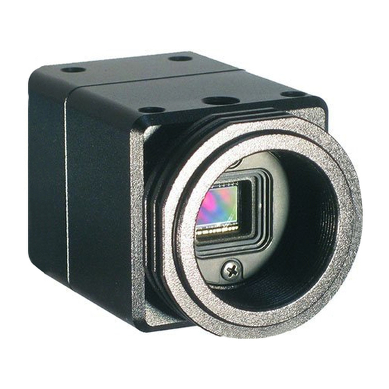
- Page 1 No.15S085-04 GigE Vision Camera 2.3Meg CMOS Color / Monochrome Color STC-SCS231POE (2.3M Monochrome STC-SBS231POE (2.3M Product Specifications and User’s Guide Sentech Co., Ltd STC-SCS231POE,STC-SBS231POE 1/44 Product Specifications and User’s Guide...
- Page 2 The camera is a general-purpose electronic device; using the camera for the equipment that may threaten human life or cause dangers to human bodies directly in case of failure or malfunction of the camera is not guaranteed. Use the camera for special purposes at your own risk. STC-SCS231POE,STC-SBS231POE 2/44 Product Specifications and User’s Guide...
-
Page 3: Table Of Contents
Electronic Specifications (STC-SBS231POE / STC-SCS231POE) ........7 Spectral Sensitivity Characteristics ..................8 2.2.1 STC-SBS231POE ..........................8 2.2.2 STC-SCS231POE (Sensor spectral response, without IR cut filter) ..........8 Mechanical Specifications ....................... 9 Environmental Specifications ....................9 Upper side of camera ..............................9 Connector Specifications ...................... 10 2.5.1... - Page 4 Gamma correction ........................38 6.7.1 Gamma table writing ........................38 ROI (Region of Interest) ......................39 Trigger ............................. 40 6.9.1 Trigger signal processing procedure .................... 40 The camera settings (GenICam parameters) control with SDK .......... 41 STC-SCS231POE,STC-SBS231POE 4/44 Product Specifications and User’s Guide...
- Page 5 Float type parameter control ......................41 6.1.3 Enumeration type parameter control ..................... 41 6.1.4 String type paramter control ......................42 6.1.5 Boolean type parameter control ....................42 6.1.6 Command type paramter control ....................42 REVISION HISTORY ................... 43 STC-SCS231POE,STC-SBS231POE 5/44 Product Specifications and User’s Guide...
-
Page 6: Introduction
No.15S085-04 Introduction This document describes the specification of the following cameras: STC-SCS231POE (2.3M Color) STC-SBS231POE (2.3M Monochrome) Features CMOS (Global Shutter) GigE Interface Support PoE (Power over Ethernet) The maximum allowed frame rate is 41.6 fps (8bit) -
Page 7: Specifications
GigE Vision® 1.2 and GenICam™ Standard Version 2.1 (SFNC 1.4) Protocol One opt-isolated input and two open collector outputs Input Voltage +10.8 to +26.4 Vdc Power Consumption +12V: 3.0W, +24V: 3.6W, PoE: 3.0W (Max/Default) Table 1: Electronic Specifications of STC-SCS231POE/ STC-SBS231POE STC-SCS231POE,STC-SBS231POE 7/44 Product Specifications and User’s Guide... -
Page 8: Spectral Sensitivity Characteristics
No.15S085-04 Spectral Sensitivity Characteristics 2.2.1 STC-SBS231POE Figure 2: Sensor Spectral Response (Mono) 2.2.2 STC-SCS231POE (Sensor spectral response, without IR cut filter) Figure 3: Sensor Spectral Response (Color) STC-SCS231POE,STC-SBS231POE 8/44 Product Specifications and User’s Guide... -
Page 9: Mechanical Specifications
Twelve M4 screws holes: (Four on each top and bottom plate, two on each side plate) Weight Approximately 100 g * excluding the connectors Table 2: Mechanical Specifications Environmental Specifications Model Number STC-SBS231POE / STC-SCS231POE Operational Minimum Environmental Temperature -5⁰C Temperature Camera housing temperature (top plate) shall not exceed 60⁰C Maximum (This corresponds to an environmental temperature of approximately 40⁰C) -
Page 10: Connector Specifications
Please use a 1GB supported NIC, Network Switcher and LAN cable. Check that the NIC and Network Switcher being used is “1GB transferring”. For the detail of Connection, please see “System Configurations (Example Connections)”. STC-SCS231POE,STC-SBS231POE 10/44 Product Specifications and User’s Guide... -
Page 11: Power And Control Signal Connector
7H-FH 7H-FH For Test Use Only Table 5: IO port Command List ※ Note: I/O-1 can be assigned only by F0H[3..0] and F1[3], and I/O-2 can be assigned only by F0H[7..4] and F1[4]. STC-SCS231POE,STC-SBS231POE 11/44 Product Specifications and User’s Guide... - Page 12 The TriggerInternal signal is the input trigger signal with the trigger delay time. 6) SensorReadOut The SensorReadOut signal is the FVAL signal, which is the image output period of the time. 7) StrobeSignal The StrobeSignal signal is the strobe control signal. STC-SCS231POE,STC-SBS231POE 12/44 Product Specifications and User’s Guide...
-
Page 13: Equivalent Circuit For The Input Pin Of The I/O Connector
No.15S085-04 2.5.3 Equivalent Circuit for the Input Pin of the I/O Connector Figure 6: Input / Output Circuit STC-SCS231POE,STC-SBS231POE 13/44 Product Specifications and User’s Guide... -
Page 14: Typical Input Circuit
No.15S085-04 2.5.4 Typical Input Circuit (+3.0 to +26.4V 3 to 5mA ) (+3.0 to +26.4V 3 to 5mA ) STC-SCS231POE,STC-SBS231POE 14/44 Product Specifications and User’s Guide... -
Page 15: Typical Output Circuit
No.15S085-04 2.5.5 Typical Output Circuit Note: Value of Vcc and Pull up register can be set within the spec of transistor. STC-SCS231POE,STC-SBS231POE 15/44 Product Specifications and User’s Guide... -
Page 16: Input And Output Signal Timing (Hardware Trigger)
15us Photocoupler output Parameter "LineDebounceTime"on GenICam Debounce Parameter "TriggerDelay"on GenICam Trigger delay Exposure Parameter "ExposureTime"on GenICam Video output Output Signal FrameTriggerWait ExposureActive TriggerAuxiliary TriggerInternal SensorReadOut StrobeSignal Parameter "StrobeSignalOnTime"on GenICam Parameter "StrobeSignalDelay"on GenICam STC-SCS231POE,STC-SBS231POE 16/44 Product Specifications and User’s Guide... -
Page 17: Input And Output Signal Timing (Software Trigger)
As for the trigger polarity, please refer to parameter "TriggerActivation"on GenICam Software trigger,PLC TriggerDelay on GenICam Trigger delay Exposure Parameter "ExposureTime"on GenICam Video output Output Signal FrameTriggerWait ExposureActive TriggerAuxiliary TriggerInternal SensorReadOut StrobeSignal Parameter "StrobeSignalDelay"on GenICam Parameter "StrobeSignalOnTime"on GenICam STC-SCS231POE,STC-SBS231POE 17/44 Product Specifications and User’s Guide... -
Page 18: Dimensions
No.15S085-04 Dimensions STC-SBS231POE Unit: mm Figure 4: Mechanical Dimensions STC-SCS231POE,STC-SBS231POE 18/44 Product Specifications and User’s Guide... -
Page 19: Stc-Scs231Poe
No.15S085-04 STC-SCS231POE Unit: mm Figure 5: Mechanical Dimensions STC-SCS231POE,STC-SBS231POE 19/44 Product Specifications and User’s Guide... -
Page 20: Sensor Information
No.15S085-04 Sensor information Pixel Transferring Image STC-SBS231POE (Monochrome) Pixel1 of Pixel2 of Data Data Pixel (n) of Data: nth pixel being transferred STC-SCS231POE (Color) Pixel11 of Pixel12 of Data Data Pixe21 of Pixel22 of Data Data Pixel (m,n) of Data: nth pixel of the mth line being transferred... -
Page 21: Camera Operational Modes
Note 1: The video output is going to be V reset by the next internal HD signal immediately after the exposure is finished. The exposure time is set by the pulse width of the trigger signal. Note 2: The FVAL signal does not output when the exposure by the trigger signal does not exist. STC-SCS231POE,STC-SBS231POE 21/44 Product Specifications and User’s Guide... -
Page 22: Exposure Timing With The Positive Polarity Trigger Signal
“LineDebounceTime” setting time. Please input more than “LineDebounceTime” time active pulse width of the trigger signal. Note 2: The exposure will start “LineDebounceTime + photocoupler delay” time after the falling edge of the input trigger signal. STC-SCS231POE,STC-SBS231POE 22/44 Product Specifications and User’s Guide... -
Page 23: Edge Preset Trigger Mode
Note 1: The video output will be V reset by the next internal HD signal immediately after the exposure is finished. Note 2: The exposure time is set by the preset electronic shutter speed. STC-SCS231POE,STC-SBS231POE 23/44 Product Specifications and User’s Guide... -
Page 24: Exposure Timing With The Positive Polarity Trigger Signal
“LineDebounceTime” setting time. Please input more than “LineDebounceTime” time active pulse width of the trigger signal. Note 2: The exposure will start “LineDebounceTime + photocoupler delay” time after the falling edge of the input trigger signal. STC-SCS231POE,STC-SBS231POE 24/44 Product Specifications and User’s Guide... -
Page 25: Edge Preset Trigger Mode (Trigger Input While The Image Is Out)
Note 1: The video output will be V reset by the next internal HD signal immediately after the exposure is finished. Note 2: The exposure time is set by the preset electronic shutter speed. STC-SCS231POE,STC-SBS231POE 25/44 Product Specifications and User’s Guide... -
Page 26: Camera Operation
UserOutput signal for 3 pin of the power-I/O connector LineInverter0 Output signal polarity for 2 pin of the power-I/O connector LineInverter1 Output signal polarity for 3 pin of the power-I/O connector StrobeSignalOnTime Strobe signal active time (us) STC-SCS231POE,STC-SBS231POE 26/44 Product Specifications and User’s Guide... - Page 27 The lower limit of the electronic shutter for auto shutter (us) Max_ShutterTime The upper limit of the electronic shutter for auto shutter (us) AGCRange AGC maximum limit TargetBrightness Target brightness for ALC ALC_Peak_Average ALC peak-average ratio STC-SCS231POE,STC-SBS231POE 27/44 Product Specifications and User’s Guide...
- Page 28 Horizontal1 position for the white balance area WB_WindowV2 Horizontal2 position for the white balance area WB_WindowMode White balance area ON/OFF YThreshold Bright level threshold for auto white balance DeviceID Serial number DeviceTemperature Inside of camera temperature STC-SCS231POE,STC-SBS231POE 28/44 Product Specifications and User’s Guide...
-
Page 29: Save And Load The Camera Setting Data
RAM, save to ROM that is selected at UserSetSelector Default Caution: Selector UserSetSave command is only available when “UserSet1” is selected UserSetSelector at UserSetSelector The camera settings saving procedure 1. Selects “UserSet1” at UserSetSelector. 2. Executes UserSetSave. STC-SCS231POE,STC-SBS231POE 29/44 Product Specifications and User’s Guide... -
Page 30: The Camera Settings Loading
Please follow the below procedure for the camera settings put back to the factory default. The settings of UserSet1 are overwrite with the settings of “Default”. The camera settings initialization procedure 1. Selects “Default” at UserSetSelector. 2. Executes UserSetLoad. 3. Selects “UserSet1” at UserSetSelector. 4. Executes UserSetSave. STC-SCS231POE,STC-SBS231POE 30/44 Product Specifications and User’s Guide... -
Page 31: Gain
Black level. Range: 0 to 63, Default: 31 Black level formula At 12bits output: Black level (grayscale) = BlackLeve * 4 At 10bits output: Black level (grayscale) = BlackLevel At 8bits output: Black level (grayscale) = BlackLevel / 4 STC-SCS231POE,STC-SBS231POE 31/44 Product Specifications and User’s Guide... -
Page 32: Alc (Auto Light Control)
When 0 sets, Average: 100%, Peak: 0%. The ALC control with the brightness average. When 255 sets, Average: 0%, Peak: 100%. The ALC control with the brightness peak. When 128 sets, Average: 50%, Peak: 50%. STC-SCS231POE,STC-SBS231POE 32/44 Product Specifications and User’s Guide... -
Page 33: Alc Control Method
GenICam parameters GainAuto Enumeration type AGC ON/OFF selection Selection: ON (Continuous) or OFF (Off). Default: OFF AGCRange Integer type Maximum gain. Range: 0 to 240, Default: 240 This is the maximum gain for AGC. STC-SCS231POE,STC-SBS231POE 33/44 Product Specifications and User’s Guide... -
Page 34: Auto Shutter
7. Sets Min_ShutterTime, if the auto shutter is using. 8. Sets Max_ShutterTime, if the auto shutter is using. 9. Sets “Continuous” at GainAuto, if AGC is using. 10. Sets “Continuous” at ExposureAuto, if the auto shutter is using. STC-SCS231POE,STC-SBS231POE 34/44 Product Specifications and User’s Guide... -
Page 35: White Balance (Only Available For The Color Cameras)
The white balance with BalanceRatio_X_Once (X: R, Gr, B or Gb) If the white balance process is not necessary, please sets 0 for BalanceRatio_X_Once (X: R, Gr, B or Gb) White balance “OFF” setting procedure 1. Sets Off at BalanceWhiteAuto. STC-SCS231POE,STC-SBS231POE 35/44 Product Specifications and User’s Guide... -
Page 36: 6.6.1.2 Auto White Balance
Preset white balance setting procedure 1. Sets the white balance gain for the preset1, 2 or 3. (X: 1 to 3) (BalanceRatio_R_PresetX, BalanceRatio_Gr_PresetX, BalanceRatio_B_PresetX, BalanceRatio_Gb_PresetX) 2. Sets PresetX (X: 1 to 3) at BalanceWhiteAuto. STC-SCS231POE,STC-SBS231POE 36/44 Product Specifications and User’s Guide... -
Page 37: White Balance Calculate Area Setting
The brightness threshold for the white balance gain calculate pixel (YThreshold) Threshold (grayscale) = YThreshold 12bits process in the camera. The white balance calculation area settings are below: WB_WindowV1 White balance gain calculation area WB_WindowV2 WB_WindowH1 WB_WindowH2 STC-SCS231POE,STC-SBS231POE 37/44 Product Specifications and User’s Guide... -
Page 38: Gamma Correction
It is necessary to use the virtual com port communication (eBUS SDK: PvSerialPort class) to write the gamma table to the camera. The gamma table cannot write the camera with GenICam parameter. Please refer the other document for the details of the gamma table writing. STC-SCS231POE,STC-SBS231POE 38/44 Product Specifications and User’s Guide... -
Page 39: Roi (Region Of Interest)
Setting steps: 8 pixels OffsetY Integer type Vertical offset for the output image (lines). Range: 0 to 1198. Default:0 Setting steps: 2 liens The ROI area settings are below: OffsetY Height ROI area OffsetX Width STC-SCS231POE,STC-SBS231POE 39/44 Product Specifications and User’s Guide... -
Page 40: Trigger
Switching point 1: Select the trigger signal setting for GenICam Sets Software at TriggerSource for the software trigger signal input. Sets Hardware at TriggerSource for the hardware =Hardware on GenICam TriggerSource=Line0 on GenICam STC-SCS231POE,STC-SBS231POE 40/44 Product Specifications and User’s Guide... -
Page 41: The Camera Settings (Genicam Parameters) Control With Sdk
Enumeration type parameter such as “BalanceWhiteAuto” control. e.g. BalanceWhiteAuto writing PvDevice.GetGenParameters()->SetEnumValue( “BalanceWhiteAuto”, “Continuous” ); [C++] PvDevice.GenParameters.SetEnumValue( “BalanceWhiteAuto”, “Continuous” ); [C#] e.g. BalanceWhiteAuto reading PvDevice.GetGenParameters()->GetEnumValue( “BalanceWhiteAuto”, &PvStringValue ); [C++] stringValue = PvDevice.GenParameters.GetEnumValueAsString( “BalanceWhiteAuto” ); [C#] STC-SCS231POE,STC-SBS231POE 41/44 Product Specifications and User’s Guide... -
Page 42: String Type Paramter Control
PvDevice.GetGenParameters()->GetBooleanValue( “LineInverter0”, &boolValue ); [C++] boolValue = PvDevice.GenParameters. GetBooleanValue( “LineInverter0” ); [C#] 6.1.6 Command type paramter control Command type parameter such as “TriggerSoftware” e.g. TriggerSoftware generating PvDevice.GetGenParameters()->ExecuteCommand( “TriggerSoftware” ); [C++] PvDevice.GenParameters.ExexuteCommand( “TriggerSoftware” ); [C#] STC-SCS231POE,STC-SBS231POE 42/44 Product Specifications and User’s Guide... -
Page 43: Revision History
2015/12/22 Deleted ROI Added Frame rate on each bits, Video Output Format. Measuring point on Environmental Specification 2016/03/04 Rotational accuracy on Optical Center Accuracy 2016/04/11 Maximum Digital Gain Value STC-SCS231POE,STC-SBS231POE 43/44 Product Specifications and User’s Guide... - Page 44 No.15S085-04 Sentech Co.,Ltd 7F, Harada center building 9-17, Naka cho 4 chome Atsugi-city, Kanagawa 243-0018 Japan TEL 81-46-295-7061 FAX 81-46-295-7066 URL http://www.sentech.co.jp/ STC-SCS231POE,STC-SBS231POE 44/44 Product Specifications and User’s Guide...
Need help?
Do you have a question about the STC-SCS231POE and is the answer not in the manual?
Questions and answers