Table of Contents
Advertisement
Advertisement
Table of Contents
Troubleshooting

Related Manuals for MQ Power DCA220SSJU4F


Summary of Contents for MQ Power DCA220SSJU4F
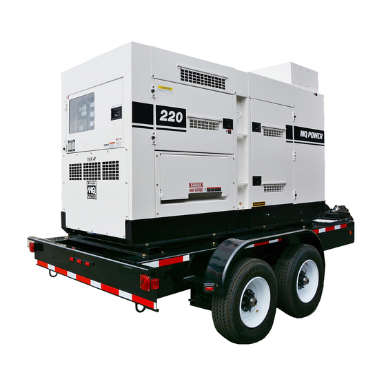
- Page 1 OPERATION MANUAL WHISPERWATT™ SERIES MODEL DCA220SSJU4F 60Hz GENERATOR (JOHN DEERE 6068HFG09 DIESEL ENGINE) Revision #3 (02/10/17) To find the latest revision of this publication, visit our website at: www.mqpower.com THIS MANUAL MUST ACCOMPANY THE EQUIPMENT AT ALL TIMES.
-
Page 2: Proposition 65 Warning
PROPOSITION 65 WARNING Diesel engine exhaust and some of PAGE 2 — DCA220SSJU4F 60 HZ GENERATOR • OPERATION MANUAL — REV. #3 (02/10/17) -
Page 3: Table Of Contents
Water Heating Element Wiring Diagram (Option) .. 58 Troubleshooting (Generator) ........59 Troubleshooting Diagnostics ......... 60 Basler DGC-2020 Programming Appendix ..61-78 NOTICE Specifications are subject to change without notice. DCA220SSJU4F 60 HZ GENERATOR• OPERATION MANUAL — REV. #3 (02/10/17) — PAGE 3... - Page 4 NOTES PAGE 4 — DCA220SSJU4F 60 HZ GENERATOR • OPERATION MANUAL — REV. #3 (02/10/17)
-
Page 5: Safety Information
COULD result in DEATH or SERIOUS INJURY. CAUTION Indicates a hazardous situation which, if not avoided, COULD result in MINOR or MODERATE INJURY. NOTICE Addresses practices not related to personal injury. DCA220SSJU4F 60 HZ GENERATOR• OPERATION MANUAL — REV. #3 (02/10/17) — PAGE 5... - Page 6 ALWAYS store equipment properly when it is not being used. Equipment should be stored in a clean, dry location out of the reach of children and unauthorized personnel PAGE 6 — DCA220SSJU4F 60 HZ GENERATOR • OPERATION MANUAL — REV. #3 (02/10/17)
- Page 7 NEVER touch the hot exhaust manifold, local Health and Safety Administrator. muffl er or cylinder. Allow these parts to cool before servicing equipment. DCA220SSJU4F 60 HZ GENERATOR• OPERATION MANUAL — REV. #3 (02/10/17) — PAGE 7...
- Page 8 Use the trailer’s swivel jack to adjust the trailer height to ALWAYS shutdown engine before transporting a level position while parked. PAGE 8 — DCA220SSJU4F 60 HZ GENERATOR • OPERATION MANUAL — REV. #3 (02/10/17)
- Page 9 ALWAYS recharge the battery in a well-ventilated possibility exists of electrical shock, environment to avoid the risk of a dangerous concentration electrocution or death. of combustible gasses. DCA220SSJU4F 60 HZ GENERATOR• OPERATION MANUAL — REV. #3 (02/10/17) — PAGE 9...
- Page 10 Recyclers and manufacturers alike promote the process of recycling metal. Using a metal recycling center promotes energy cost savings. PAGE 10 — DCA220SSJU4F 60 HZ GENERATOR • OPERATION MANUAL — REV. #3 (02/10/17)
-
Page 11: Specifications
Fuel Consumption 6.9 gal. (26.1 L)/hr at 1/2 load 4.4 gal. (16.7 L)/hr at 1/4 load Battery 12 (150Ah X 1 Includes engine and radiator hoses Includes filters DCA220SSJU4F 60 HZ GENERATOR• OPERATION MANUAL — REV. #3 (02/10/17) — PAGE 11... -
Page 12: Dimensions
43.70 in. (1,110 mm) 35.83 in. (910 mm) 137.79 in. (3,500 mm) 43.70 in. (1,110 mm) 70.86 in. (1,800 mm) 41.34 in. (1,050 mm) 51.18 in. (1,300 mm) PAGE 12 — DCA220SSJU4F 60 HZ GENERATOR • OPERATION MANUAL — REV. #3 (02/10/17) -
Page 13: Installation
INSTALLATION GENERATOR GROUND LUG GROUND ROD FOR EARTH GROUND. CONNECT TO BUILDING GROUND CABLE GROUND IF APPLICABLE REFERENCE NEC 250-83 (C) Figure 2. Typical Generator Grounding Application DCA220SSJU4F 60 HZ GENERATOR• OPERATION MANUAL — REV. #3 (02/10/17) — PAGE 13... -
Page 14: Installation
NFPA 110, Chapter 5-4.1). DO NOT remove the metal skids on the bottom of the generator. They are to resist damage to the bottom of the generator and to maintain alignment. PAGE 14 — DCA220SSJU4F 60 HZ GENERATOR • OPERATION MANUAL — REV. #3 (02/10/17) -
Page 15: General Information
Use the cable selection chart (Table 7) as a „ Battery Charger (Optional) guide for selecting proper extension cable size. „ Camloks (Optional) „ Jacket Water Heater (Optional) DCA220SSJU4F 60 HZ GENERATOR• OPERATION MANUAL — REV. #3 (02/10/17) — PAGE 15... -
Page 16: General Paralleling Information (Option)
(as it would if it were operating alone) but It will lead to an increase in the proportion of the total kVAR load it will deliver and a decrease in its power factor. PAGE 16 — DCA220SSJU4F 60 HZ GENERATOR • OPERATION MANUAL — REV. #3 (02/10/17) - Page 17 Next, the cursor will move to the password field, press the up arrow button () and scroll to the alpha character A, then press edit to select. DCA220SSJU4F 60 HZ GENERATOR• OPERATION MANUAL — REV. #3 (02/10/17) — PAGE 17...
-
Page 18: General Paralleling Information (Option)
When connecting load cables to the power distribution panel be sure to select the correct size of the load cables to handle full load/amperage of both generators (parallel). PAGE 18 — DCA220SSJU4F 60 HZ GENERATOR • OPERATION MANUAL — REV. #3 (02/10/17) -
Page 19: Major Components
Fuel Tank Assembly Output Terminal Assembly Circuit Breaker Assembly Denyo Auto Start/Stop Controller Assembly Gauge Unit Assembly Operating Panel Assembly Voltage Change-Over Board Figure 4. Major Components DCA220SSJU4F 60 HZ GENERATOR• OPERATION MANUAL — REV. #3 (02/10/17) — PAGE 19... -
Page 20: Engine Controller Unit (Ecu 835)
DPF Force Regen and diagnostic code engine condition and the possibility of engine to be confirmed. shutdown.The diagnostic fault message will be displayed on the LCD screen PAGE 20 — DCA220SSJU4F 60 HZ GENERATOR • OPERATION MANUAL — REV. #3 (02/10/17) -
Page 21: Engine/Generator Control Panel
U,V, and W 4. Frequency Meter — Indicates the output frequency Output Terminal Lugs from overload. in hertz (Hz). Normally 60 Hz DCA220SSJU4F 60 HZ GENERATOR• OPERATION MANUAL — REV. #3 (02/10/17) — PAGE 21... -
Page 22: Basler Digital Genset Controller (Option)
The Basler DGC-2020HD is an option. It replaces the ECU 835 that comes standard with this generator. For detailed programming information refer to the Basler programming appendix in this manual. PAGE 22 — DCA220SSJU4F 60 HZ GENERATOR • OPERATION MANUAL — REV. #3 (02/10/17) -
Page 23: Basler Digital Genset Controller (Option)
If the bus is already hot from another generator it will first synchronize then close its contactor then slowly ramp up to share load if load were present DCA220SSJU4F 60 HZ GENERATOR• OPERATION MANUAL — REV. #3 (02/10/17) — PAGE 23... -
Page 24: Paralleling Panel (Option)
PARALLELING PANEL (OPTION) Figure 8. Paralleling Panel Components PAGE 24 — DCA220SSJU4F 60 HZ GENERATOR • OPERATION MANUAL — REV. #3 (02/10/17) - Page 25 “OFF” button. While in the “OFF” mode, “OPEN CONTACTOR” button twice will immediately the “RESET” button must be pressed to clear the open the contactor. E-STOP fault. DCA220SSJU4F 60 HZ GENERATOR• OPERATION MANUAL — REV. #3 (02/10/17) — PAGE 25...
-
Page 26: Output Terminal Panel Familiarization
FOR CS-6369 TWIST FOR GFCI RECEPTACLES LOCK RECEPTACLES 120 VAC, 20 AMP GFCI RECEPTACLES CS-6369 TWIST-LOCK AUX. POWER RECEPTACLES 240/139V, 50 AMPS Figure 9. Output Terminal Panel PAGE 26 — DCA220SSJU4F 60 HZ GENERATOR • OPERATION MANUAL — REV. #3 (02/10/17) - Page 27 These receptacles can be accessed in any change-over board configuration. RETAINING BOLT Figure 13. Protective Terminal Cover (UVWO Terminal Lugs) Figure 11. 240/139V Twist-Lock Auxiliary Receptacles DCA220SSJU4F 60 HZ GENERATOR• OPERATION MANUAL — REV. #3 (02/10/17) — PAGE 27...
-
Page 28: Output Terminal Panel Familiarization
To restore power to the Output Terminal Panel, press the reset button on the overcurrent relay and place the main circuit breaker in the closed position (ON). PAGE 28 — DCA220SSJU4F 60 HZ GENERATOR • OPERATION MANUAL — REV. #3 (02/10/17) -
Page 29: Load Application
150 ft. 100 ft. 1800 3600 150 ft. 100 ft. 65 ft. 2400 4800 125 ft. 75 ft. 50 ft. CAUTION: Equipment damage can result from low voltage DCA220SSJU4F 60 HZ GENERATOR• OPERATION MANUAL — REV. #3 (02/10/17) — PAGE 29... -
Page 30: Generator Outputs
Voltage Change-Over Board Terminal Lugs 3-Phase 240/139V Position 3-Phase 480/270V Position 3Ø Line-Line 208V 220V 240V 416V 440V 480V 1Ø Line-Neutral 120V 127V 139V 240V 254V 277V PAGE 30 — DCA220SSJU4F 60 HZ GENERATOR • OPERATION MANUAL — REV. #3 (02/10/17) -
Page 31: Gauge Reading
W and U terminals as indicated on the AC Voltmeter Gauge (Figure 19). Figure 18. AC Voltmeter Figure 19. AC Voltmeter Gauge Change-Over Switch (Volt reading on W-U Lug) DCA220SSJU4F 60 HZ GENERATOR• OPERATION MANUAL — REV. #3 (02/10/17) — PAGE 31... -
Page 32: Output Terminal Panel Connections
240 VAC (LOAD CONNECTIONS) AT ALL TIMES SINGLE-PHASE 120 VAC (LOAD CONNECTIONS) Figure 23. UVWO Terminal Lugs 3Ø-240/1Ø-139 Connections Figure 26. UVWO Terminal Lugs 1Ø-120V Connections PAGE 32 — DCA220SSJU4F 60 HZ GENERATOR • OPERATION MANUAL — REV. #3 (02/10/17) - Page 33 277 VAC (LOAD CONNECTIONS) MUST BE USED AT ALL TIMES THREE-PHASE Figure 30. UVWO Terminal Lugs 1Ø-277V 480 VAC (LOAD CONNECTIONS) Connections Figure 28. UVWO Terminal Lugs 3Ø-480V Connection DCA220SSJU4F 60 HZ GENERATOR• OPERATION MANUAL — REV. #3 (02/10/17) — PAGE 33...
-
Page 34: Inspection/Setup
When replacing engine oil please refill using Delo ® 400 LE SAE 15W-40 (API CJ-4) engine oil. Table 10. Recommended Motor Oil Trailer Fuel Tank Figure 32. Internal Fuel Tank System PAGE 34 — DCA220SSJU4F 60 HZ GENERATOR • OPERATION MANUAL — REV. #3 (02/10/17) - Page 35 3. NEVER overfill fuel tank — It is important to read the Figure 37. DEF Tank Filling fuel gauge when filling trailer fuel tank. DO NOT wait for fuel to rise in filler neck (Figure 35). DCA220SSJU4F 60 HZ GENERATOR• OPERATION MANUAL — REV. #3 (02/10/17) — PAGE 35...
- Page 36 Freezing Point Vol % Anti-Freeze °C °F NOTICE When the antifreeze is mixed with water, the antifreeze mixing ratio must be less than 50%. PAGE 36 — DCA220SSJU4F 60 HZ GENERATOR • OPERATION MANUAL — REV. #3 (02/10/17)
-
Page 37: Inspection/Setup
Tighten all hose clamps and check hoses for leaks. Figure 39. Battery Connections If any hose (fuel or oil) lines are defective replace them immediately. DCA220SSJU4F 60 HZ GENERATOR• OPERATION MANUAL — REV. #3 (02/10/17) — PAGE 37... -
Page 38: Generator Start-Up Procedure (Manual)
4. Tighten terminal nuts securely to prevent load wires from slipping out. 5. Close all engine enclosure doors (Figure 41). Figure 43. Frequency Meter CORRECT INCORRECT Figure 41. Engine Enclosure Doors PAGE 38 — DCA220SSJU4F 60 HZ GENERATOR • OPERATION MANUAL — REV. #3 (02/10/17) - Page 39 Under normal 17. The generator will run until manually stopped or an operating conditions the coolant temperature should abnormal condition occurs. be between 185°~207°F (85°~97°C). DCA220SSJU4F 60 HZ GENERATOR• OPERATION MANUAL — REV. #3 (02/10/17) — PAGE 39...
-
Page 40: Generator Start-Up Procedure (Auto Mode)
NOTICE When the Auto Off/Reset Manual Switch is placed in the AUTO position, the engine glow plugs will be warmed and the engine will start automatically. PAGE 40 — DCA220SSJU4F 60 HZ GENERATOR • OPERATION MANUAL — REV. #3 (02/10/17) -
Page 41: Generator Shut-Down Procedures
OFF (not lit). 5. Remove all loads from the generator. 6. Inspect entire generator for any damage or loosening of components that may have occurred during operation. DCA220SSJU4F 60 HZ GENERATOR• OPERATION MANUAL — REV. #3 (02/10/17) — PAGE 41... -
Page 42: Maintenance
1500 hrs. is not necessary. The emissions-related warranty is valid up to 1500 hrs. Replace primary air filter element when restriction indicator shows a vacuum of 625 mm (25 in. H PAGE 42 — DCA220SSJU4F 60 HZ GENERATOR • OPERATION MANUAL — REV. #3 (02/10/17) - Page 43 This can lead to a loss of power, excessive carbon buildup in the combustion chamber and high fuel consumption. Change air cleaner more frequently if these conditions exists. DCA220SSJU4F 60 HZ GENERATOR• OPERATION MANUAL — REV. #3 (02/10/17) — PAGE 43...
- Page 44 „ Flush the radiator by running clean tap water through shown in Figure 31. radiator until signs of rust and dirt are removed. DO NOT clean radiator core with any objects, such as a screwdriver. PAGE 44 — DCA220SSJU4F 60 HZ GENERATOR • OPERATION MANUAL — REV. #3 (02/10/17)
- Page 45 To ensure adequate starting capability, always have place on blocks so tires do not touch the ground or block power applied to the generator's internal battery and completely remove the tires. charger.. DCA220SSJU4F 60 HZ GENERATOR• OPERATION MANUAL — REV. #3 (02/10/17) — PAGE 45...
- Page 46 Acknowledge Change Exit of removing the accumulated soot from the filter. This Figure 62. ECU DPF Pre-Alarm regeneration process can occur in a few different ways. PAGE 46 — DCA220SSJU4F 60 HZ GENERATOR • OPERATION MANUAL — REV. #3 (02/10/17)
- Page 47 Normal service intervals for cleaning ash from the DPF is every 6 months (5000 hours). Alarm Screen Program Option Acknowledge Change Exit Figure 64. ECU DEF State Pre-Alarm DCA220SSJU4F 60 HZ GENERATOR• OPERATION MANUAL — REV. #3 (02/10/17) — PAGE 47...
- Page 48 DEF<10% Tank Level DEF<10% Tank Level DEF Tank Empty Level DEF Symbol — Blinking Blinking Pre-Alarm Lamp — — Shutdown Lamp — — — Engine Shutdown PAGE 48 — DCA220SSJU4F 60 HZ GENERATOR • OPERATION MANUAL — REV. #3 (02/10/17)
-
Page 49: Maintenance
Press the “Alarm Silence” and the “Lamp Test” buttons at the same time for 5 seconds. To exit the diagnostic mode you can press reset, start the engine or turn control power off. DCA220SSJU4F 60 HZ GENERATOR• OPERATION MANUAL — REV. #3 (02/10/17) — PAGE 49... -
Page 50: Generator Wiring Diagram
WIRE COLOR CIRCUIT BLACK BREAKER BLUE WHITE SIDE BROWN YELLOW GREEN LIGHT BLUE CB1 CONNECTOR GRAY LIGHT GREEN ORANGE VIOLET (VIEW FROM INSERTING PINK WIRE SIDE) PAGE 50 — DCA220SSJU4F 60 HZ GENERATOR • OPERATION MANUAL — REV. #3 (02/10/17) -
Page 51: Generator Wiring Diagram, Basler (Option)
GENERATOR WIRING DIAGRAM, BASLER (OPTION) DCA220SSJU4F 60 HZ GENERATOR• OPERATION MANUAL — REV. #3 (02/10/17) — PAGE 51... -
Page 52: Engine Wiring Diagram (Ecu 835)
ENGINE WIRING DIAGRAM (ECU 835) PAGE 52 — DCA220SSJU4F 60 HZ GENERATOR • OPERATION MANUAL — REV. #3 (02/10/17) -
Page 53: Engine Wiring Diagram (Basler Dgc2020Hd Option)
ENGINE WIRING DIAGRAM (BASLER DGC2020HD OPTION) DCA220SSJU4F 60 HZ GENERATOR• OPERATION MANUAL — REV. #3 (02/10/17) — PAGE 53... - Page 54 NOTES PAGE 54 — DCA220SSJU4F 60 HZ GENERATOR • OPERATION MANUAL — REV. #3 (02/10/17)
-
Page 55: 3Ø-480 Vac Parallel Wiring Diagram
3Ø-480 VAC PARALLEL WIRING DIAGRAM PARALLEL WIRING CONNECTIONS VIA CAMLOKS DCA220SSJU4F 3-PHASE 480 VAC DCA220SSJU4F 60 HZ GENERATOR• OPERATION MANUAL — REV. #3 (02/10/17) — PAGE 55... -
Page 56: 3Ø-208 Vac Parallel Wiring Diagram
3Ø-208 VAC PARALLEL WIRING DIAGRAM PARALLEL WIRING CONNECTIONS VIA CAMLOKS DCA220SSJU4F 3-PHASE 208 VAC PAGE 56 — DCA220SSJU4F 60 HZ GENERATOR • OPERATION MANUAL — REV. #3 (02/10/17) -
Page 57: Battery Charger Wiring Diagram (Option)
BATTERY CHARGER WIRING DIAGRAM (OPTION) DCA220SSJU4F 60 HZ GENERATOR• OPERATION MANUAL — REV. #3 (02/10/17) — PAGE 57... -
Page 58: Water Heating Element Wiring Diagram (Option)
WATER HEATING ELEMENT WIRING DIAGRAM (OPTION) PAGE 58 — DCA220SSJU4F 60 HZ GENERATOR • OPERATION MANUAL — REV. #3 (02/10/17) -
Page 59: Troubleshooting (Generator)
Check load and repair. Over current? Confirm load requirements and reduce. Circuit Breaker Tripped Defective circuit breaker? Check and replace. Over current Relay actuated? Confirm load requirement and replace. DCA220SSJU4F 60 HZ GENERATOR• OPERATION MANUAL — REV. #3 (02/10/17) — PAGE 59... -
Page 60: Troubleshooting Diagnostics
ECU controller. 4. Releasing the Hour Check Button and pushing the Program/Exit Button on the ECU controller will return the controller to the main screen. PAGE 60 — DCA220SSJU4F 60 HZ GENERATOR • OPERATION MANUAL — REV. #3 (02/10/17) -
Page 61: Basler Dgc-2020 Programming Appendix
3. Press Edit to send the selected breaker command request. Generator metering. Touch the generator in the diagram to view metered voltage, current, frequency, kW, kvar, and power factor values of the local generator. DCA220SSJU4F 60 HZ GENERATOR• OPERATION MANUAL — REV. #3 (02/10/17) — PAGE 61... - Page 62 Disconnect the nine terminal block connectors; the Start, Run, and Pre relays; and the Ethernet (copper or fiber), USB, and DB-9 connectors. Lay the front panel face-down on a suitable work surface. PAGE 62 — DCA220SSJU4F 60 HZ GENERATOR • OPERATION MANUAL — REV. #3 (02/10/17)
- Page 63 The front panel display is used to locally make settings changes and display metering values. Refer to items 11, 12 and 13 in Figure 6 for information on changing settings through the front panel and navigating through the screens. DCA220SSJU4F 60 HZ GENERATOR• OPERATION MANUAL — REV. #3 (02/10/17) — PAGE 63...
- Page 64 The one-line diagram appears on both the front panel Overview and Summary screens. Figure D, illustrates the different configurations of the one-line diagram. PAGE 64 — DCA220SSJU4F 60 HZ GENERATOR • OPERATION MANUAL — REV. #3 (02/10/17)
- Page 65 (failed or stable) is indicated by a red colored line segment. See Figure E for the different breaker and bus states. DCA220SSJU4F 60 HZ GENERATOR• OPERATION MANUAL — REV. #3 (02/10/17) — PAGE 65...
- Page 66 After the scroll time delay has elapsed, the next set of values is displayed and so on. When scrolled metering is disabled, only the following parameters are displayed on the overview screen: • VOLT∗ • AMP∗ • PH∗ • • PAGE 66 — DCA220SSJU4F 60 HZ GENERATOR • OPERATION MANUAL — REV. #3 (02/10/17)
- Page 67 Temperature Detectors (RTD): AEM3 RTD4 Analog Expansion Module 2: Inputs: AEM2 In7 Analog Expansion Module 3: Resistance Analog Expansion Module 2: Inputs: AEM2 In8 Temperature Detectors (RTD): AEM3 RTD5 DCA220SSJU4F 60 HZ GENERATOR• OPERATION MANUAL — REV. #3 (02/10/17) — PAGE 67...
- Page 68 Bus 1 Current: Average Bus 2 Current: I1 Bus 1 Current: I1 Bus 2 Current: I2 Bus 1 Current: I2 Bus 2 Current: Phase A Current PAGE 68 — DCA220SSJU4F 60 HZ GENERATOR • OPERATION MANUAL — REV. #3 (02/10/17)
- Page 69 Contact Expansion Module 1: CEM1 Input 3 Contact Expansion Module 1: CEM1 Input 4 Contact Inputs: Input 14 Contact Expansion Module 1: CEM1 Input 5 Contact Inputs: Input 15 DCA220SSJU4F 60 HZ GENERATOR• OPERATION MANUAL — REV. #3 (02/10/17) — PAGE 69...
- Page 70 Generated kvar Gen Current: Average Generated kW Gen Current: Ground Current Injector Metering Rail Pressure Gen Current: I1 Intake Manifold Temperature kvar Error Gen Current: I2 PAGE 70 — DCA220SSJU4F 60 HZ GENERATOR • OPERATION MANUAL — REV. #3 (02/10/17)
- Page 71 Breakers in the system are listed at the bottom of the Summary screen. To send an open or close request to a breaker in the system, move the cursor to the desired breaker in the list and press Edit. Press the up DCA220SSJU4F 60 HZ GENERATOR• OPERATION MANUAL — REV. #3 (02/10/17) — PAGE 71...
- Page 72 Bus 2 Voltage Current Frequency Power Energy Vector Shift • Synchronization • Differential Phase A Phase B Phase C Phase Neutral Bias Control • Var Mode PAGE 72 — DCA220SSJU4F 60 HZ GENERATOR • OPERATION MANUAL — REV. #3 (02/10/17)
- Page 73 System Group Bus System Load Bus Power Breaker Sum • Real Time Clock • Gen Network Status Units Act Seg Units Units Online Sys Online kW Cap DCA220SSJU4F 60 HZ GENERATOR• OPERATION MANUAL — REV. #3 (02/10/17) — PAGE 73...
- Page 74 Clock Setup Display Units • Communication Ethernet Ethernet 2 (Visible when redundant Ethernet is disabled.) Redundant Ethernet CAN Bus 1 (I/O) Setup CAN Bus 2 (ECU) Setup PAGE 74 — DCA220SSJU4F 60 HZ GENERATOR • OPERATION MANUAL — REV. #3 (02/10/17)
- Page 75 Configurable Protection • Breaker Management Breaker Management Breaker Hardware Bus Condition Synchronizer Breaker Power Sum • Bias Control AVR Bias Control GOV Bias Control Mains Power Control DCA220SSJU4F 60 HZ GENERATOR• OPERATION MANUAL — REV. #3 (02/10/17) — PAGE 75...
- Page 76 BESTCOMSPlus. The display options are described below. Figure F shows the BESTCOMSPlus Front Panel HMI settings screen. Settings are listed in Table B. PAGE 76 — DCA220SSJU4F 60 HZ GENERATOR • OPERATION MANUAL — REV. #3 (02/10/17)
- Page 77 Scroll Time Delay 1 to 600 varies seconds Phase Toggle Delay 0 to 120 seconds Up to 16 alphanumeric Initializing Message characters Touchscreen Disable Enabled or Disabled DCA220SSJU4F 60 HZ GENERATOR• OPERATION MANUAL — REV. #3 (02/10/17) — PAGE 77...
-
Page 78: Basler Dgc-2020 Programming Appendix
Open. If successful, the image appears in the Splash Screen in BESTCOMSPlus. Upload settings to the DGC-2020HD to transfer the image. PAGE 78 — DCA220SSJU4F 60 HZ GENERATOR • OPERATION MANUAL — REV. #3 (02/10/17) - Page 79 NOTES DCA220SSJU4F 60 HZ GENERATOR• OPERATION MANUAL — REV. #3 (02/10/17) — PAGE 79...
- Page 80 © COPYRIGHT 2017, MULTIQUIP INC. Multiquip Inc , the MQ logo and the MQ Power logo are registered trademarks of Multiquip Inc. and may not be used, reproduced, or altered without written permission. All other trademarks are the property of their respective owners and used with permission.
Need help?
Do you have a question about the DCA220SSJU4F and is the answer not in the manual?
Questions and answers