Table of Contents
Advertisement
Quick Links
QQ
3 7 63 1515 0
SERVICE MANUAL
注 :"4. ブロックダイヤクラム"は,別冊 (9-928-133-31)
に記載されています。
NOTE : "SECTION 4 DIAGRAMS" is provided in the
separate manual (9-928-133-31).
TE
L 13942296513
www
.
9-928-133-01
http://www.xiaoyu163.com
Power supply
AC power adapter: AC-PLM3
100-240 V AC, 50/60 Hz, 16 W
Output voltage 8.4 V, 1.6 A
Battery pack: NP-F550/F750/F950
(not supplied)
Power consumption
10 W (approx., PC mode)
12 W (approx., VIDEO mode)
Operating temperature
41°F to 95°F (5°C to 35°C)
Storage temperature
14°F to 140°F (–10°C to 60°C)
Dimensions
Display unit:
× 1
× 3
Approx. 5
7
/
15
/
8
16
(Approx. 149 × 48 × 86 mm)
(w/h/d folded)
Power supply box:
× 1
× 6
1
7
Approx. 2
/
/
4
8
(Approx. 54 × 47 × 160 mm)
(w/h/d)
not including projecting parts and
controls
Mass
Display unit: Approx. 4.2 oz. (120 g)
Power supply box: Approx. 9.2 oz. (260 g)
Video signal
NTSC color, CCIR standards
x
ao
y
i
http://www.xiaoyu163.com
LDI-D100B
8
SPECIFICATIONS
VIDEO Input
PC mode
RGB signal: HD15
Pin Assignment
Q Q
3
6 7
1 3
Pin No.
1
2
3
4
5
1
/
inches
2
6
7
8
3
/
inches
8
9
10
11
12
13
14
15
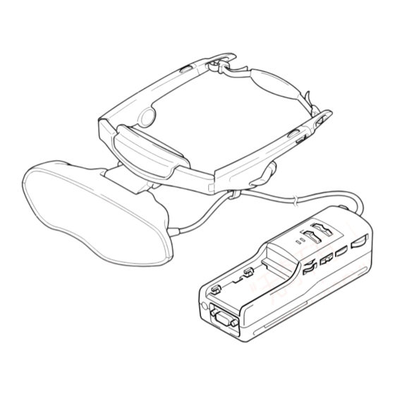
パーソナルLCDディスプレイ
u163
.
2 9
9 4
2 8
NTSC Model
5 4 3 2 1
10 9
8 7 6
1 5
0 5
8
2 9
9 4
15 14 13 12 11
Signal
R (Red)
G (Green)
B (Blue)
–
GND
R (Red) GND
G (Green) GND
B (Blue) GND
–
GND
GND
–
SYNC (Horizontal)
SYNC (Vertical)
–
– Continued on next page –
m
PERSONAL LCD DISPLAY
co
9 9
2 8
9 9
Advertisement
Table of Contents

Related Manuals for Sony LDI-D100B


Summary of Contents for Sony LDI-D100B
- Page 1 LDI-D100B 3 7 63 1515 0 SERVICE MANUAL NTSC Model 注 :“4. ブロックダイヤクラム”は,別冊 (9-928-133-31) に記載されています。 NOTE : “SECTION 4 DIAGRAMS” is provided in the separate manual (9-928-133-31). SPECIFICATIONS Power supply VIDEO Input AC power adapter: AC-PLM3 PC mode 100-240 V AC, 50/60 Hz, 16 W RGB signal: HD15 Output voltage 8.4 V, 1.6 A...
- Page 2 SONY PARTS WHOSE PART NUMBERS APPEAR AS DE FONCTIONNEMENT. NE REMPLACER CES COM- SHOWN IN THIS MANUAL OR IN SUPPLEMENTS PUB- POSANTS QUE PAR DES PIÈCES SONY DONT LES LISHED BY SONY. NUMÉROS SONT DONNÉS DANS CE MANUEL OU DANS LES SUPPLÉMENTS PUBLIÉS PAR SONY.
-
Page 3: Table Of Contents
http://www.xiaoyu163.com 3 7 63 1515 0 TABLE OF CONTENTS 概要 GENERAL ダイヤグラム (別冊:9-928-133-31) パーソナル LCD ディスプレイは, DIAGRAMS (Separete Volume: 9-928-133-31) 新しいタイプの映像ディスプレイです ....1-1 4-1. Block Diagram – AUDIO/VIDEO Section – ..... 4-1 パーソナル LCD ディスプレイとは ......1-1 4-2. Block Diagram 各部のなまえ... - Page 4 http://www.xiaoyu163.com 1. 概 要 3 7 63 1515 0 L 13942296513 u163 http://www.xiaoyu163.com...
- Page 5 http://www.xiaoyu163.com 3 7 63 1515 0 L 13942296513 u163 http://www.xiaoyu163.com...
- Page 6 http://www.xiaoyu163.com 3 7 63 1515 0 L 13942296513 u163 http://www.xiaoyu163.com...
- Page 7 http://www.xiaoyu163.com 3 7 63 1515 0 L 13942296513 u163 http://www.xiaoyu163.com...
- Page 8 http://www.xiaoyu163.com 3 7 63 1515 0 L 13942296513 u163 http://www.xiaoyu163.com...
- Page 9 http://www.xiaoyu163.com 3 7 63 1515 0 L 13942296513 u163 http://www.xiaoyu163.com...
- Page 10 http://www.xiaoyu163.com 3 7 63 1515 0 L 13942296513 u163 http://www.xiaoyu163.com...
-
Page 11: About The Personal Lcd Display
WARNING The Personal LCD Display is a head-mounted display. With this type of display, the screen is Sony Personal LCD Display. The Personal YOUR FAILURE TO FOLLOW THESE always in front of you even when you move your head. Because of this feature, you can... -
Page 12: Connecting The Personal Lcd Display
http://www.xiaoyu163.com 3 7 63 1515 0 Connecting the Personal LCD Display Connecting the Personal LCD Display (continued) Connecting a PC Connecting a Macintosh Powerbook Depending on the model, you may need to use a commercially available adapter to connect a Be sure to turn off your PC before connecting the power supply box. - Page 13 http://www.xiaoyu163.com 3 7 63 1515 0 Connecting the Personal LCD Display (continued) Notes on CONTROL connector Connecting video equipment (3D stereoscopic picture) The CONTROL connector uses the special type of the stereo miniplug shown in Figure 1 below. Connect a VCR, laser disc player, or camcorder to the power supply box using a commercially Note that the connector of the video equipment or video cables may differ from the CONTROL available audio/video cable as shown below.
-
Page 14: Wearing The Personal Lcd Display
http://www.xiaoyu163.com 3 7 63 1515 0 Wearing the Personal LCD Display Wearing the Personal LCD Display (continued) WARNING Adjust the angle of the display unit. • Failure to properly fit the product each time may result in eye fatigue, eye damage, or loss While holding the front pad against of visual functions and may result in accident or injury. -
Page 15: Viewing The Surrounding Environment
http://www.xiaoyu163.com 3 7 63 1515 0 Viewing the surrounding environment While you are wearing the Personal LCD Display, you can view the surrounding environment After you finish using the through the screen: Personal LCD Display Take off the Personal LCD Display, and Viewing the surrounding turn off the power. - Page 16 http://www.xiaoyu163.com 3 7 63 1515 0 Adjusting the sound and picture (continued) AVLS (Auto Volume Limiter POWER SAVE Press MENU. System) Turn the jog dial to set to The menu display appears on the screen. PC mode Turn the jog dial to set to ON, then press the jog dial.
-
Page 17: Using The Optional Battery Pack
NP-F950 Approx. 18 hours Approx. 3 hours You can return your unwanted lithium ion batteries to your nearest Sony Service Center or •The battery life and charging time may change depending on the conditions of use. Factory Service Center. •You can also use a battery pack such as the NP-500/510/710/F530/F730/F930 (not supplied) with NOTE: In some areas the disposal of lithium ion batteries in household or business trash may be the Personal LCD Display. -
Page 18: Disassembly
http://www.xiaoyu163.com 2. 外し方 SECTION 2 DISASSEMBLY 3 7 63 1515 0 • 図中に1など番号のあるものは,その番号順に外す。 Note: Follow the disassembly procedure in the numerial order given. LOADING BLOCK ASSY 1 screw (M1.4 × 3.0) 2 loading block assy 6 FP661 flexible board (CN803) 1 screw 1 three screws (M1.4 ×... - Page 19 http://www.xiaoyu163.com 3 7 63 1515 0 BACK LIGHT UNIT 1 screw (M1.7 × 5) 3 back light unit 2 claw L 13942296513 OPTICS BLOCK ASSY, FILM (PANEL) LIQUID CRYSTAL 1 screw (P1.7 × 4.0) 3 optics block assy 2 lens fixed plate 4 shutter holder (C) u163 5 two film (panel) liquid crystals (C)
-
Page 20: 電気調整
http://www.xiaoyu163.com 3. 電気調整 3 7 63 1515 0 【調整時の注意】 5. 入力信号のセットアップ (1) ビデオ確認 1. 調整は掲載順に行う。 本機の調整にはパターンジェネレータから得られるビデ 2. 電源電圧:DC8.4V オ信号を調整信号として用いますので,このビデオ出力 3. 使用機器 信号が規格内に入っていることが必要です。 電気調整には下記に示す測定器類を使用します。 映像入力端子にオシロスコープを接続し,ビデオ信号の (1) オシロスコープ2現象,帯域30 MHz以上,ディレイモー 同期信号振幅が約286mV,映像部分の振幅が約714mV, ド付 (特に指定のない限り10:1のプローブを使用する バースト信号の振幅が約286mVで平坦になっているこ こと) と,バースト信号と 「赤」 信号のレベル比が0.30:0.705で (2) パターンジェネレータ あることを確認して下さい。 (3) 安定化電源 (4) デジタルボルトメータ •... - Page 21 http://www.xiaoyu163.com 3 7 63 1515 0 • 調整データの書き込み 【調整前の準備】 1. サービス治具 調整データ (E またはF ページ) を不揮発性メモリ 調整リモコン (RM-95-部改造品) 注1:J-6082-053-B (EEPROM) に書き込むためにはPAUSEボタンを押す 延長ケーブル (リモコンプラグ変換用) J-6082-291-A 必要があります。 (この操作を行わない場合,新しい 注1:調整リモコン内のマイコンICが新マイコン (uPD7503- データは不揮発性メモリに記憶されません) G-C56-12) でないとページ切換が出来ません。この場 ページ:0,アドレス:01を選択し,データを01にしま 合には新マイコン (8-759-148-35) に交換してください。 す。これによってEまたはFページのデータ入力が可能 2. 調整リモコン になります。 調整を行うためには,不揮発性メモリ (EEPROM) に書き 調整終了後はページ:0,アドレス:01を選択し,デー...
- Page 22 http://www.xiaoyu163.com 3 7 63 1515 0 5. データ処理 一部の調整項目において,調整データを得るためにマイコンデータを読み取り,治具や調整リモコンの表示データ (16進 数) の演算を必要とします。この場合,16進数を一旦10進数に変換した後に演算を行い,その解を16進数に変換して調整 データとして下さい。表1. に16進数−10進数変換表を示します。 16進数−10進数変換表 ↓ 16進数 の下位桁 (A) (b) (c) (d) (E) (F) 16進数の 上位桁 A (A) B (b) 1→ C (c) L 13942296513 D (d) E (E) F ( F) 表...
- Page 23 http://www.xiaoyu163.com 3 7 63 1515 0 6. 調整時の電源投入手順 延長ケーブル,調整リモコンをつなぐ。 調整リモコンのHOLDスイッチが入っていないこと (左 (NOR) 位置) を確認し,DC IN 8.4Vジャック (J701) に8.4Vdcを投 入する。 (HOLDスイッチがHOLDになっているとセットの初期動作が終了できず,電源スイッチが機能しません) セットの電源スイッチを入れる。この時緑LED点灯を確認する。 [PC] [VIDEO] セットを または モードにする。 調整リモコンのHOLDスイッチをHOLD (右 (ADJ) 位置) にする。 7. 調整終了手順 ページ アドレス データ 作業内容 備考 順序 (1) EまたはF 左記のページ,アドレスに調整した値が正しく書き...
- Page 24 http://www.xiaoyu163.com 3 7 63 1515 0 【プリセットデータ書き込み】 接続: [VIDEO] (1) MA-324 ( H) 基板CN501に調整リモコンを接続し, モード (S904) にする。 データ書き込み方法 (1) ページ:0,アドレス:01にデータ:01をセットする。 (2) 下表のデータを入力する。 注:データをEEPROMに書き込むため,データをセットするたびに調整リモコンのPAUSEボタンを押してください。 (3) 全データ書き込みの後,ページ:0,アドレス:01にデータ:00をセットする。 E,Fページ調整アドレスと初期設定データ IC502 ( EEPROM) を交換したときのみ設定し所定の調整を行ってください。 E:ページ アドレス データ 備考 アドレス データ 備考 アドレス データ 備考 固定値...
- Page 25 http://www.xiaoyu163.com 3 7 63 1515 0 アドレス データ 備考 アドレス データ 備考 アドレス データ 備考 固定値 SID 調整 PRG 調整 BLACK 調整 固定値 バッテリダウン 調整 固定値 固定値 L 13942296513 固定値 充電動作調整 固定値 CONTRAST調整 HUE調整 カラー調整 固定値 u163 http://www.xiaoyu163.com...
- Page 26 http://www.xiaoyu163.com 3 7 63 1515 0 ビデオ部 【ビデオミュートレベル調整】 条件: • ビデオ部の調整は下記のようにパターンジェネレータを接 入力信号 全黒 (IRE 0%) 信号 続して下さい。文中に調整用映像入力信号として指示がな 測定点 YC-148 ( H) 基板のCN10037ピン い限りビデオ出力信号 (カラーバー信号) を入力して下さ 測定器 オシロスコープ い。 調整ページ 調整アドレス パターンジェネレータ 規格値 0±0.03Vp-p セット 接続: オシロスコープ (DCレンジ) S-VIDEOジャック(J1401) YC-148(H)基板 準備: CN10037ピン(Y OUT)...
- Page 27 http://www.xiaoyu163.com 3 7 63 1515 0 調整方法: 【ビデオCONTRAST調整】 (1) YC-148 ( H) 基板のCN10038ピンにオシロスコープを接 条件: 続する。 入力信号 10ステップ信号 (白:100IREレベル) (2) ページ:0,アドレス:01にデータ:01をセット (確認) 測定点 YC-148 ( H) 基板のCN10038ピン する。 (Fページ:プロテクト解除) 測定器 オシロスコープ (3) ページ:F,アドレス:98にしオシロスコープ上の波形 調整ページ のCレベルが規格値になるよう,PLAY,STOPボタン 調整アドレス でデータを変え,PAUSEボタンを押して書き込む。 規格値 0.7±0.02Vp-p 接続: オシロスコープ (DCレンジ)...
- Page 28 http://www.xiaoyu163.com 3 7 63 1515 0 PC部 【シグナルセンタレベル調整】 準備: • PC部の調整を行う時は,セットを [PC] モードにして下さ ページ アドレス データ 備考 い。 BRIGHT (センタ) • MA-324 ( H) 基板のJ101より,PC RGB信号を入力します。 BRIGHT (固定) 下表にJ101の端子番号と信号名称を記します。 条件: 端子番号 信号名称 端子番号 信号名称 入力信号 SVGA60Hz:全黒信号 SYNC GND 測定点 MA-324 ( H) 基板のCN2063ピン GREEN 測定器...
- Page 29 http://www.xiaoyu163.com 3 7 63 1515 0 注: R,G,Bの調整は温度により変化するので電源投入後 調整方法: 5分以内に行って下さい。 (1) MA-324 ( H) 基板のCN2061ピンにオシロスコープを接 【R GAIN調整】 続する。 (2) ページ:0,アドレス:01にデータ:01をセット (確認) 条件: する。 (Fページ:プロテクト解除) 入力信号 SVGA60Hz:RGB0.7Vp-p,16Step信号 (3) ページ:F,アドレス:6Bにしオシロスコープ上の波形 測定点 MA-324 ( H) 基板のCN2061ピン のGレベルが規格値になるよう,PLAY,STOPボタン 測定器 オシロスコープ でデータを変え,PAUSEボタンを押して書き込む。 調整ページ 黒レベル 調整アドレス 規格値...
- Page 30 http://www.xiaoyu163.com 3 7 63 1515 0 調整方法: 【G BIAS調整】 (1) MA-324 ( H) 基板のCN2065ピンにオシロスコープを接 条件: 続する。 入力信号 SVGA60Hz:RGB0.7Vp-p,16Step信号 (2) ページ:0,アドレス:01にデータ:01をセット (確認) 測定点 MA-324 ( H) 基板のCN2063ピン する。 (Fページ:プロテクト解除) 測定器 オシロスコープ (3) ページ:F,アドレス:6Aにしオシロスコープ上の波形 調整ページ のJレベルが規格値になるよう,PLAY,STOPボタン 調整アドレス でデータを変え,PAUSEボタンを押して書き込む。 規格値 8.4±0.1Vp-p 黒レベル 接続: オシロスコープ...
- Page 31 http://www.xiaoyu163.com 3 7 63 1515 0 【SIDレベル調整】 調整方法: 条件: (1) MA-324 ( H) 基板のCN206qhピンにオシロスコープを接 続する。 入力信号 SVGA60Hz:RGB0.7Vp-p,16Step信号 (2) ページ:0,アドレス:01にデータ:01をセット (確認) 測定点 MA-324 ( H) 基板のCN206qhピン する。 (Fページ:プロテクト解除) 測定器 オシロスコープ (3) ページ:F,アドレス:79にしオシロスコープ上の波形 調整ページ のMレベルが規格値になるよう,PLAY,STOPボタン 調整アドレス でデータを変え,PAUSEボタンを押して書き込む。 規格値 9.1±0.1Vp-p 接続: オシロスコープ (DCレンジ) MA-324(H)基板...
- Page 32 http://www.xiaoyu163.com 3 7 63 1515 0 黒レベル 調整方法: (1) MA-324 ( H) 基板のCN206qfピンにデジタルボルトメー タを接続する。 (2) ページ:0,アドレス:01にデータ:01をセット (確認) する。 (Fページ:プロテクト解除) (3) ページ:F,アドレス:76にしてデジタルボルトメータ の読みが規格値になるよう,PLAY,STOPボタンで 黒レベル データを変え,PAUSEボタンを押して書き込む。 調整および接続箇所:MA-324 ( H) 基板 (3-30ページ参照) 調整および接続箇所:MA-324 ( H) 基板 (3-30ページ参照) 【VCOM R調整】 【ホワイトバランス調整】 条件: 準備: 入力信号 SVGA60Hz:RGB0.7Vp-p,16Step信号...
- Page 33 http://www.xiaoyu163.com 3 7 63 1515 0 装着センサ部 電源部 【装着センサレベル調整】 【充電動作調整】 モード モード RGB入力:無信号 入力信号 無信号 信号 PC AUDIO入力:無信号 測定点 調整リモコン表示データ 音量:最小 測定器 測定点 調整ページ 調整リモコン表示データ 測定器 調整アドレス 調整ページ E,F 調整方法: 01,02,03,04,05 ( ページ:E) 調整アドレス (1) センサ部から6.5±0.1cm離れた位置にケント紙 (方眼無 FE (ページ:F) し面) を貼った反射板をセットする。 接続:...
- Page 34 http://www.xiaoyu163.com 3 7 63 1515 0 (18) 次式 (16進数の計算) によって調整データを算出しそれ ぞれの調整アドレスに入力する。 (3-3ページの5.データ処理を参照) ページ:E, アドレス:02 = YYh ページ:E, アドレス:03 = YYh−02h ページ:E, アドレス:04 = YYh−55h ページ:E, アドレス:05 = YYh+02h (19) ページ:0,アドレス:01にデータ:00をセットする。 注: 各データをセットした後,必ず調整リモコンのPAUSE ボタンを押してください。 【バッテリダウン調整】 モード RGB入力:無信号 信号 PC AUDIO入力:無信号 音量:最小 測定点...
-
Page 35: Electrical Adjustments
http://www.xiaoyu163.com SECTION 3 ELECTRICAL ADJUSTMENTS 3 7 63 1515 0 Precautions on adjustment: 5. Setting up Input Signals 1. Perform the adjustment in the given order. (1) Video Signal 2. Power supply voltage: DC 8.4 V In adjusting this set, video signals obtained from the pattern 3. - Page 36 http://www.xiaoyu163.com 3 7 63 1515 0 [Preparation for Adjustment] 4. Select page: 0, address: 01, and set 01 data. Thus, the data 1. Service Jigs input to page: E or F is enabled. 1. Adjusting remote commander (RM-95-modified) 5. After the adjustment finished, select page: 0, address: 01, and Note: J-6082-053-B set 00 data.
- Page 37 http://www.xiaoyu163.com 3 7 63 1515 0 5. Data Processing Certain adjustment items require the microprocessor data to be read out or the displayed data (hexadecimal numbers) on jigs or adjusting remote commander to be calculated to get adjustment data. In such a case, convert hexadecimal numbers into decimal numbers once, then make calculation, and convert its result into hexadecimal number as adjustment data.
- Page 38 http://www.xiaoyu163.com 3 7 63 1515 0 6. Power ON Procedure for Adjustment 1. Connect an extension cable to the adjusting remote commander. [PC] [VIDEO] 2. Set the mode on the set. 3. After making sure that the HOLD switch on the adjusting remote commander is not turned on (not at left (NOR) position), supply 8.4 Vdc to the DC IN 8.4 V jack (J701).
- Page 39 http://www.xiaoyu163.com 3 7 63 1515 0 [Preset Data Writing] Connection: [VIDEO] (1) Connect the adjusting remote commander to the CN501 on MA-324 (H) board, and set the mode (S904). Data Writing Procedure (1) Set data: 01 to page: 0, address: 01. (2) Enter the data given in the table below.
- Page 40 http://www.xiaoyu163.com 3 7 63 1515 0 Address Data Remarks Address Data Remarks Address Data Remarks Battery down adj. Fixed value Charge adj. Fixed value Fixed value Video contrast adj. Hue adj. Color adj. L 13942296513 Fixed value Fixed value u163 3-21 http://www.xiaoyu163.com...
- Page 41 http://www.xiaoyu163.com 3 7 63 1515 0 [Video Mute Level Adjustment] VIDEO BLOCK Condition: To adjust the video block, connect a pattern generator as shown Input signal All black (IRE 0%) signal (No set up) below. As video input signals for adjustment, enter video output Measurement point YC-148 (H) board CN1003 pin 7 signals (color bar signals), unless otherwise specified.
- Page 42 http://www.xiaoyu163.com 3 7 63 1515 0 [Video Contrast Adjustment] Adjustment Procedure: Condition: (1) Connect a oscilloscope to the CN1003 pin 8 on the YC-148 (H) board. Input signal 10 step signal (White: 100 IRE level) (2) Set (or confirm) data: 01 to page 0, address 01. (Cancel F Measurement point YC-148 (H) board CN1003 pin 8 page protect)
- Page 43 http://www.xiaoyu163.com 3 7 63 1515 0 [Signal Center Level Adjustment] PC BLOCK Preparation: • To adjust the PC block, set the PC mode on the set. Page Address Data Remarks • For the PC block adjustment, input a PC RGB signals to J101 BRIGHT (Center) on the MA-324 (H) board.
- Page 44 http://www.xiaoyu163.com 3 7 63 1515 0 Note: RGB Gain/Bias adjustment relate to temperature, therefore adjust- Adjustment Procedure: ment within 5 minutes after supplied power. (1) Connect an oscilloscope to the CN206 pin 1 on the MA- 324 (H) board. [R Gain Adjustment] (2) Set (or confirm) data: 01 to page: 0, address: 01.
- Page 45 http://www.xiaoyu163.com 3 7 63 1515 0 [G Bias Adjustment] Adjustment Procedure: Condition: (1) Connect an oscilloscope to the CN206 pin 5 on the MA- 324 (H) board. Input signal SVGA 60 Hz: RGB 0.7 Vp-p, 16 Step (2) Set (or confirm) data: 01 to page: 0, address: 01. Measurement point MA-324 (H) board CN206 pin 3 (Cancel F page protect)
- Page 46 http://www.xiaoyu163.com 3 7 63 1515 0 [SID Level Adjustment] Adjustment Procedure: Condition: (1) Connect an oscilloscope to the CN206 pin qh on the MA- 324 (H) board. Input signal SVGA 60 Hz: RGB 0.7 Vp-p, 16 Step (2) Set (or confirm) data: 01 to page: 0, address: 01. Measurement point MA-324 (H) board CN206 pin qh (Cancel F page protect)
- Page 47 http://www.xiaoyu163.com 3 7 63 1515 0 [VCOM R Adjustment] [White Balance Adjustment] Condition: Preparation: Set data: 1F to page: F, address: 7B. Input signal SVGA 60 Hz: RGB 0.7 Vp-p, 16 Step Measurement point MA-324 (H) board CN206 pin qs Condition: Measuring equipment Digital voltmeter...
- Page 48 http://www.xiaoyu163.com 3 7 63 1515 0 [Battery Down Adjustment] POWER SUPPLY BLOCK Mode [Charge Adjustment] RGB IN: No signal Mode Signal PC AUDIO IN: No signal VOLUME: Minimum RGB IN: No signal Signal PC AUDIO IN: No signal Measurement point Displayed data on adj.
- Page 49 http://www.xiaoyu163.com 3 7 63 1515 0 adjusting remote commander RM-95 extension cable (J-6082-053-B) (J-6082-291-A) DC IN 8.4 V jack (J701) battery terminals RGB terminal digital digital J101 voltmeter voltmeter – – regulated regulated power supply power supply – – Fig. 3-4 Adjustment and Connection Location: CN501 Connect the adjusting...
-
Page 50: Ic Block Diagrams
http://www.xiaoyu163.com 5. ICダイヤグラム 3 7 63 1515 0 SECTION 5 IC DIAGRAMS 5-1. IC BLOCK DIAGRAMS – YC-148 (H) Board – IC1001 µPC1830GT-E2 42 41 29 28 27 25 24 23 FILTER 3.58MHz/4.43MHz SEPARATE/COMPOSITE OUTPUT MODE SYSTEM SELECT, ACC, VCXO, PAL SELECT fo ADJUSTMENT SUB COLOR CONTROL... - Page 51 http://www.xiaoyu163.com 3 7 63 1515 0 IC1005 TC74HC4538AFT (EL) IC1009, 1010 NJM2534V (TE2) 16 15 14 10 9 BUFFER 6 7 8 BIAS IC1012, 1016 TC7W74FU (TE12R) IC1101-1103 CXD1176Q-T4 23 22 18 17 L 13942296513 VRBS 16 AVDD 15 PW –...
- Page 52 http://www.xiaoyu163.com 3 7 63 1515 0 IC1104-1106 µPD485505G-35-E2 24 23 22 21 20 19 18 17 16 15 14 13 WRITE ADDRESS POINTER 40,384 BIT INPUT OUTPUT (5,048 X 8) BUFFER BUFFER MEMORY CELL ARRAY READ ADDRESS POINTER 1 2 3 4 5 6 7 8 9 10 11 12 IC1201 CXD1178Q-T6...
- Page 53 http://www.xiaoyu163.com 3 7 63 1515 0 – MA-324 (H) Board – IC131 BA7657F-E2 24 23 LOGIC SYNC SEPARATOR 11 12 IC151 BA3574BFS-E2 L 13942296513 MUTE SW 11 MUTE MUTE BB SW MUTE SW PW SW 12 P.SW AVC DET IN 1 13 AVC IN MIX OUT IN 2 14...
- Page 54 http://www.xiaoyu163.com 3 7 63 1515 0 IC201 TGA-A2111HF 38 37 36 35 34 33 32 31 30 29 28 27 GAM G B2P GAM B B2P 41 B IN GAM R WHG 42 CLP LEV GAM G WHG 43 G IN GAM B WHG 44 γ...
- Page 55 http://www.xiaoyu163.com 3 7 63 1515 0 IC202-204 TGA-A2112HF 48 47 44 43 42 41 40 39 37 36 INVERT BIAS VCOM GND2 DLY CNT SH OUT1 BUFFER MCLK 50 OFFSET CANCEL MCLK/ 51 CLOCK DELAY BUFFER SH OUT2 INV CNT 52 VDD 53 OFFSET CANCEL CLK OUT 54...
- Page 56 http://www.xiaoyu163.com 3 7 63 1515 0 IC205, 206, 507 MB88346BPFV-EF 8 BIT 8 BIT LATCH D/A CONVERTER D0-D7 8 BIT 8 BIT D/A CONVERTER LATCH D0-D7 8 BIT 8 BIT LATCH D/A CONVERTER D0-D7 8 BIT 8 BIT D/A CONVERTER LATCH D0-D7 8 BIT...
- Page 57 http://www.xiaoyu163.com 3 7 63 1515 0 IC207 M62359FP-650D GAIN DETERMINE LATCH & OUTPUT BUFFER D13 (MSB) 8 BIT UPPER SEGMENT R-2R 8 BIT LATCH 8 BIT LATCH 8 BIT UPPER D0 (LSB) SEGMENT R-2R GAIN DETERMINE LATCH & OUTPUT BUFFER 8 9 10 IC301 TGA-D2442HA L 13942296513...
- Page 58 http://www.xiaoyu163.com 3 7 63 1515 0 IC304 TC74VHC153FS (EL) IC443 CXA1616N-T4 DATA INPUTS STROBE OUTPUT 2C3 2C2 2C1 2C0 SELECT 2C3 2C2 2C1 2C0 LOGIC 1C3 1C2 1C1 1C0 EXIST EXIST STROBE 1C3 1C2 1C1 1C0 OUTPUT CHECK CHECK SELECT DATA INPUTS V.RAMP GENERATOR...
- Page 59 http://www.xiaoyu163.com 3 7 63 1515 0 IC701 MB3785APFV-G-BND-ER 36 35 34 33 32 31 30 28 27 26 25 –IN 3 (C) CB 4 CTL 3 VE 4 CTL 2 OUT 4 CTL 1 +2.5V OUT 3 VOLTAGE VREF REFERENCE VE 3 VE 2 XTAL...
-
Page 60: Ic Pin Function Description
http://www.xiaoyu163.com 3 7 63 1515 0 5-2. IC PIN FUNCTION DESCRIPTION • MA-324 (H) BOARD IC301 TGA-D2442HA (LCD TIMING GENERATOR) Pin No. Pin Name Description Pulse output for the phase comparator Not used (open) — Ground terminal CKI2 Clock signal input from the PLL (IC302) (SVGA, VGA) HSYNC Horizontal sync signal input from the PLL (IC302) VSYNC... - Page 61 http://www.xiaoyu163.com 3 7 63 1515 0 Pin No. Pin Name Description MODE2 Mode changes signal output to the L & R LCD units MODE1 Mode changes signal output to the L & R LCD units Horizontal start pulse output to the L & R LCD units HCK1 Horizontal clock 1 pulse output to the L &...
- Page 62 http://www.xiaoyu163.com 3 7 63 1515 0 • MA-324 (H) BOARD IC302 CXA3106Q-T6 (PLL) Pin No. Pin Name Description IOVCC — Power supply terminal (+5V) (digital system) IOGND — Ground terminal (digital system) VCOH External VCO input terminal Not used (open) VCOL External inverted VCO input terminal Not used (open) External VCO input terminal Not used (open)
- Page 63 http://www.xiaoyu163.com 3 7 63 1515 0 Pin No. Pin Name Description — Connection terminal of low-pass filter for the charge pump IRGND — Ground terminal (for IREF circuit/analog system) IRVCC — Power supply terminal (+5V) (for IREF circuit/analog system) L 13942296513 u163 5-14 http://www.xiaoyu163.com...
- Page 64 http://www.xiaoyu163.com 3 7 63 1515 0 • MA-324 (H) BOARD IC401 MB90096PF-G-150-BND (ON SCREEN DISPLAY CONTROLLER) Pin No. Pin Name Description CPOUT Horizontal sync phase comparison result output terminal Not used (open) AVSS1 — Ground terminal (for internal VCO) VCOIN Internal VCO voltage input terminal Not used (fixed at “L”) AVSS2 —...
- Page 65 http://www.xiaoyu163.com 3 7 63 1515 0 • MA-324 (H) BOARD IC501 S579193PZ-TEB (SYSTEM CONTROLLER) Pin No. Pin Name Description LANC IN LANC data input for adjustment LANC OUT LANC data output for adjustment XS CONT Video selection signal output terminal “L”: S terminal, “H”: composite Not used (open) —...
- Page 66 http://www.xiaoyu163.com 3 7 63 1515 0 Pin No. Pin Name Description XCS OSD Chip select signal output to the on screen display controller (IC401) “L” active MOD UNDEF Output terminal for the test (signal judgment result uncertain (“H” active)) Not used (open) PLL ERROR Output terminal for the test (PLL communication (7h) error (“H”...
- Page 67 http://www.xiaoyu163.com 3 7 63 1515 0 Pin No. Pin Name Description DC IN MON Connection detect signal input of the DC IN jack (J701) “L”: DC IN jack connected BATT IN MON Connection detect signal input of the battery pack “L”: battery pack connected 86, 87 —...
-
Page 68: 分解図
http://www.xiaoyu163.com 6. 分解図 SECTION 6 EXPLODED VIEWS 3 7 63 1515 0 【分解図】 【使用上の注意】 • 外装部品色表示 • *印の部品は常時在庫しておりません。 • 分解図中の機構部品で,図面番号のない部品は供給しません。 例:バランスツマミ(ホワイト) ..(レッド) • -XX,-Xは標準化部品のため,セットに付いている部品と異なる場 ↑ ↑ 部品の色を表す。 セットの色を表す。 合があります。 • 付属梱包部は,部品表の最後尾にあります。 0印の部品,または0印付きの点線で囲まれた部品は, 安全性を維持するために重要な部品です。 従って交換時は,必ず指定の部品を使用して下さい。 NOTE: The components identified by mark 0 or dotted line with mark 0 are •... - Page 69 http://www.xiaoyu163.com 3 7 63 1515 0 (1) OPTICS BLOCK SECTION 12 13 Cable, connection (See page 5-5.) L 13942296513 0印の部品,または0印付きの点線で囲まれた部品は, The components identified by mark Les composants identifiés par une 0 or dotted line with mark 0 are marque 0 sont critiquens pour la 安全性を維持するために重要な部品です。...
- Page 70 http://www.xiaoyu163.com 3 7 63 1515 0 (2) LOADING BLOCK SECTION-1 L 13942296513 supplied Ref. No. Part No. Description Remark Ref. No. Part No. Description Remark 1-670-349-11 FP-661 FLEXIBLE BOARD X-3948-835-1 COVER ASSY, PAD 3-050-046-01 SHAFT, HINGE 3-713-791-41 SCREW (M1.7X5), TAPPING, P2 3-050-057-01 HOOK, SPRING 3-050-011-02 SHAFT (L), PAD 3-050-119-11 CABINET (FRONT), FRONT...
- Page 71 http://www.xiaoyu163.com 3 7 63 1515 0 (3) LOADING BLOCK SECTION-2 supplied supplied supplied supplied HP402 (included in HP401) supplied L 13942296513 HP401 (including HP402) supplied Ref. No. Part No. Description Remark Ref. No. Part No. Description Remark 3-050-053-01 RETAINER, HP CORD 3-050-049-01 HOOK (R) (REAR), BELT 3-704-197-32 SCREW (M1.4X3.0) 3-713-791-01 SCREW (M1.7X5), TAPPING, P2...
- Page 72 http://www.xiaoyu163.com 3 7 63 1515 0 (4) IF-BOX BLOCK SECTION-1 supplied L 13942296513 supplied supplied Ref. No. Part No. Description Remark Ref. No. Part No. Description Remark X-4621-960-1 CABINET (IF) ASSY, LOWER 3-050-071-01 SLIDE, BATT RELEASE 3-050-089-01 COVER, D-SUB A-8056-070-A SW-306 (H) MOUNT 3-718-233-01 NUT, PLATE 4-640-759-01 SHEET (L), HEAT SINK 3-719-381-31 SCREW (M2X3)
- Page 73 http://www.xiaoyu163.com 3 7 63 1515 0 (5) IF-BOX BLOCK SECTION-2 not supplied M701 not supplied not supplied supplied supplied L 13942296513 Ref. No. Part No. Description Remark Ref. No. Part No. Description Remark A-8056-072-A MA-324 (H) COMPL 3-050-336-01 SHEET (B), MA RADIATION X-3948-754-1 CASE (UPPER) ASSY, MA SHIELD 3-050-083-01 CASE (LOWER), MA SHIELD 1-783-673-11 CABLE, CONNECTION...
-
Page 74: 電気部品表
http://www.xiaoyu163.com 7. 電気部品表 DD-107 (H) SECTION 7 ELECTRICAL PARTS LIST 3 7 63 1515 0 【使用上の注意】 • ここに記載されている部品は,補修用部品であるため,回路 • インダクタの単位で,uHはμHを示します。 • 半導体の名称でuA…,uPA…,uPB…,uPC…,uPD…等はそれ 図及びセットに付いている部品と異なる場合があります。 • -XX,-Xは標準化部品のため,セットに付いている部品と ぞれμA…,μPA…,μPB…,μPC…,μPD…を示します。 異なる場合があります。 • *印の部品は常時在庫しておりません。 お願い • コンデンサの単位でuFはμFを示します。 図面番号で部品を指定するときは基板名,またはブロック • 抵抗の単位Ωは省略してあります。 を併せて指定して下さい。 金被 ︰金属被膜抵抗 サンキン︰酸化金属被膜抵抗 0印の部品,または0印付きの点線で囲まれた部品は, 安全性を維持するために重要な部品です。 従って交換時は,必ず指定の部品を使用して下さい。... - Page 75 http://www.xiaoyu163.com DD-107 (H) 3 7 63 1515 0 Ref. No Part No. Description Remark Ref. No Part No. Description Remark C789 1-113-981-11 TANTALUM CHIP 22uF FL709 1-234-108-21 FILTER, EMI C790 1-164-947-11 CERAMIC CHIP 0.01uF < IC > C791 1-117-370-11 CERAMIC CHIP 10uF C792 1-111-253-11 TANTALUM CHIP 100uF...
- Page 76 http://www.xiaoyu163.com DD-107 (H) JK-136 (H) LC-61 (F) 3 7 63 1515 0 Ref. No Part No. Description Remark Ref. No Part No. Description Remark Q795 8-729-045- TRANSISTOR MMDF2P02HDR2 R784 1-218-863-11 METAL CHIP 4.7K 0.5% 1/16W Q796 8-729-045- TRANSISTOR MMDF2P02HDR2 R785 1-216-200-11 RES, CHIP 1.2K...
- Page 77 http://www.xiaoyu163.com LC-61 (F) 3 7 63 1515 0 Ref. No Part No. Description Remark Ref. No Part No. Description Remark C806 1-164-874-11 CERAMIC CHIP 100PF FL820 1-234-107-21 FILTER, EMI C807 1-164-326-91 CERAMIC CHIP 0.47uF C808 1-164-326-91 CERAMIC CHIP 0.47uF FL821 1-234-107-21 FILTER, EMI C809...
- Page 78 http://www.xiaoyu163.com MA-324 (H) 3 7 63 1515 0 Ref. No Part No. Description Remark Ref. No Part No. Description Remark A-8056-072-A MA-324 (H) COMPL C165 1-135-150-91 TANTALUM CHIP 3.3uF 6.3V **************** C166 1-164-346-11 CERAMIC CHIP 1uF 1-670-350-11 FP-662 FLEXIBLE BOARD C167 1-163-038-91 CERAMIC CHIP 0.1uF...
- Page 79 http://www.xiaoyu163.com MA-324 (H) 3 7 63 1515 0 Ref. No Part No. Description Remark Ref. No Part No. Description Remark C262 1-165-319-11 CERAMIC CHIP 0.1uF C267 1-107-820-11 CERAMIC CHIP 0.1uF C451 1-164-489-11 CERAMIC CHIP 0.22uF C268 1-107-820-11 CERAMIC CHIP 0.1uF C452 1-164-489-11 CERAMIC CHIP 0.22uF...
- Page 80 http://www.xiaoyu163.com MA-324 (H) 3 7 63 1515 0 Ref. No Part No. Description Remark Ref. No Part No. Description Remark C554 1-164-858-11 CERAMIC CHIP 22PF C555 1-164-858-11 CERAMIC CHIP 22PF < CONNECTOR > C556 1-164-858-11 CERAMIC CHIP 22PF CN101 1-573-924-11 CONNECTOR, FFC/FPC (ZIF) 15P C557 1-164-858-11...
- Page 81 http://www.xiaoyu163.com MA-324 (H) 3 7 63 1515 0 Ref. No Part No. Description Remark Ref. No Part No. Description Remark FB326 1-500-329-11 INDUCTOR CHIP FL210 1-234-107-21 FILTER, EMI FB327 1-500-329-11 INDUCTOR CHIP FL211 1-234-107-21 FILTER, EMI FB328 1-500-329-11 INDUCTOR CHIP FL212 1-234-107-21 FILTER, EMI...
- Page 82 http://www.xiaoyu163.com MA-324 (H) 3 7 63 1515 0 Ref. No Part No. Description Remark Ref. No Part No. Description Remark IC506 8-759-337-40 IC NJM2904V (TE2) Q209 8-729-928-19 TRANSISTOR 2SA1774TL-QR IC507 8-759-064-36 IC MB88346BPFV-EF IC508 8-759-079-75 IC TC74VHC161FS (EL) Q210 8-729-928-05 TRANSISTOR 2SC4617TL-QR IC931...
- Page 83 http://www.xiaoyu163.com MA-324 (H) 3 7 63 1515 0 Ref. No Part No. Description Remark Ref. No Part No. Description Remark R207 1-218-929-11 RES, CHIP 1/16W R289 1-218-881-11 METAL CHIP 0.5% 1/16W R209 1-218-929-11 RES, CHIP 1/16W R212 1-218-965-11 RES, CHIP 1/16W R292 1-218-990-11...
- Page 84 http://www.xiaoyu163.com MA-324 (H) 3 7 63 1515 0 Ref. No Part No. Description Remark Ref. No Part No. Description Remark R369 1-218-929-11 RES, CHIP 1/16W R551 1-218-953-11 RES, CHIP 1/16W R370 1-218-990-11 SHORT R376 1-218-990-11 SHORT R552 1-218-953-11 RES, CHIP 1/16W R377 1-218-990-11...
- Page 85 http://www.xiaoyu163.com MA-324 (H) SW-306 (H) 3 7 63 1515 0 Ref. No Part No. Description Remark Ref. No Part No. Description Remark R643 1-218-981-11 RES, CHIP 220K 1/16W R956 1-218-954-11 RES, CHIP 1.2K 1/16W R644 1-218-969-11 RES, CHIP 1/16W R645 1-218-965-11 RES, CHIP 1/16W...
- Page 86 http://www.xiaoyu163.com SW-306 (H) YC-148 (H) 3 7 63 1515 0 Ref. No Part No. Description Remark Ref. No Part No. Description Remark D912 8-719-404-50 DIODE MA111-TX C1029 1-164-943-11 CERAMIC CHIP 0.01uF < TRANSISTOR > C1030 1-162-920-11 CERAMIC CHIP 27PF C1031 1-107-726-91 CERAMIC CHIP 0.01uF Q901...
- Page 87 http://www.xiaoyu163.com YC-148 (H) 3 7 63 1515 0 Ref. No Part No. Description Remark Ref. No Part No. Description Remark C1094 1-164-388-91 CERAMIC CHIP 270PF C1095 1-164-388-91 CERAMIC CHIP 270PF C1213 1-164-858-11 CERAMIC CHIP 22PF C1096 1-164-156-11 CERAMIC CHIP 0.1uF C1251 1-104-851-11 TANTALUM CHIP 10uF...
- Page 88 http://www.xiaoyu163.com YC-148 (H) 3 7 63 1515 0 Ref. No Part No. Description Remark Ref. No Part No. Description Remark FB1305 1-414-385-11 FERRITE BEAD IC1106 8-759-277-19 IC uPD485505G-35-E2 FB1306 1-414-385-11 FERRITE BEAD IC1108 8-759-523-46 IC TC74VHC04FT (EL) FB1311 1-414-385-11 FERRITE BEAD FB1312 1-414-385-11 FERRITE BEAD...
- Page 89 http://www.xiaoyu163.com YC-148 (H) 3 7 63 1515 0 Ref. No Part No. Description Remark Ref. No Part No. Description Remark Q1261 8-729-042-28 TRANSISTOR 2SD2216J-QR (K8).SO Q1262 8-729-042-26 TRANSISTOR 2SB1462J-QR (K8).SO R1054 1-218-946-11 RES, CHIP 1/16W Q1271 8-729-042-28 TRANSISTOR 2SD2216J-QR (K8).SO R1055 1-218-951-11 RES, CHIP...
- Page 90 http://www.xiaoyu163.com YC-148 (H) 3 7 63 1515 0 Ref. No Part No. Description Remark Ref. No Part No. Description Remark R1120 1-218-929-11 RES, CHIP 1/16W R1121 1-218-929-11 RES, CHIP 1/16W R1183 1-218-865-11 METAL CHIP 5.6K 0.5% 1/16W R1122 1-218-929-11 RES, CHIP 1/16W R1184 1-218-871-11...
- Page 91 LDI-D100B YC-148 (H) 3 7 63 1515 0 Ref. No Part No. Description Remark Ref. No Part No. Description Remark R1257 1-218-953-11 RES, CHIP 1/16W ACCESSORIES & PACKING MATERIALS R1258 1-218-953-11 RES, CHIP 1/16W ***************************** R1259 1-218-953-11 RES, CHIP...
- Page 92 http://www.xiaoyu163.com 7. 電気部品表 DD-107 (H) SECTION 7 ELECTRICAL PARTS LIST 3 7 63 1515 0 【使用上の注意】 • ここに記載されている部品は,補修用部品であるため,回路 • インダクタの単位で,uHはμHを示します。 • 半導体の名称でuA…,uPA…,uPB…,uPC…,uPD…等はそれ 図及びセットに付いている部品と異なる場合があります。 • -XX,-Xは標準化部品のため,セットに付いている部品と ぞれμA…,μPA…,μPB…,μPC…,μPD…を示します。 異なる場合があります。 • *印の部品は常時在庫しておりません。 お願い • コンデンサの単位でuFはμFを示します。 図面番号で部品を指定するときは基板名,またはブロック • 抵抗の単位Ωは省略してあります。 を併せて指定して下さい。 金被 ︰金属被膜抵抗 サンキン︰酸化金属被膜抵抗 0印の部品,または0印付きの点線で囲まれた部品は, 安全性を維持するために重要な部品です。 従って交換時は,必ず指定の部品を使用して下さい。...
- Page 93 http://www.xiaoyu163.com DD-107 (H) 3 7 63 1515 0 Ref. No Part No. Description Remark Ref. No Part No. Description Remark C789 1-113-981-11 TANTALUM CHIP 22uF FL709 1-234-108-21 FILTER, EMI C790 1-164-947-11 CERAMIC CHIP 0.01uF < IC > C791 1-117-370-11 CERAMIC CHIP 10uF C792 1-111-253-11 TANTALUM CHIP 100uF...
- Page 94 http://www.xiaoyu163.com DD-107 (H) JK-136 (H) LC-61 (F) 3 7 63 1515 0 Ref. No Part No. Description Remark Ref. No Part No. Description Remark Q795 8-729-045- TRANSISTOR MMDF2P02HDR2 R784 1-218-863-11 METAL CHIP 4.7K 0.5% 1/16W Q796 8-729-045- TRANSISTOR MMDF2P02HDR2 R785 1-216-200-11 RES, CHIP 1.2K...
- Page 95 http://www.xiaoyu163.com LC-61 (F) 3 7 63 1515 0 Ref. No Part No. Description Remark Ref. No Part No. Description Remark C806 1-164-874-11 CERAMIC CHIP 100PF FL820 1-234-107-21 FILTER, EMI C807 1-164-326-91 CERAMIC CHIP 0.47uF C808 1-164-326-91 CERAMIC CHIP 0.47uF FL821 1-234-107-21 FILTER, EMI C809...
- Page 96 http://www.xiaoyu163.com MA-324 (H) 3 7 63 1515 0 Ref. No Part No. Description Remark Ref. No Part No. Description Remark A-8056-072-A MA-324 (H) COMPL C165 1-135-150-91 TANTALUM CHIP 3.3uF 6.3V **************** C166 1-164-346-11 CERAMIC CHIP 1uF 1-670-350-11 FP-662 FLEXIBLE BOARD C167 1-163-038-91 CERAMIC CHIP 0.1uF...
- Page 97 http://www.xiaoyu163.com MA-324 (H) 3 7 63 1515 0 Ref. No Part No. Description Remark Ref. No Part No. Description Remark C262 1-165-319-11 CERAMIC CHIP 0.1uF C267 1-107-820-11 CERAMIC CHIP 0.1uF C451 1-164-489-11 CERAMIC CHIP 0.22uF C268 1-107-820-11 CERAMIC CHIP 0.1uF C452 1-164-489-11 CERAMIC CHIP 0.22uF...
- Page 98 http://www.xiaoyu163.com MA-324 (H) 3 7 63 1515 0 Ref. No Part No. Description Remark Ref. No Part No. Description Remark C554 1-164-858-11 CERAMIC CHIP 22PF C555 1-164-858-11 CERAMIC CHIP 22PF < CONNECTOR > C556 1-164-858-11 CERAMIC CHIP 22PF CN101 1-573-924-11 CONNECTOR, FFC/FPC (ZIF) 15P C557 1-164-858-11...
- Page 99 http://www.xiaoyu163.com MA-324 (H) 3 7 63 1515 0 Ref. No Part No. Description Remark Ref. No Part No. Description Remark FB326 1-500-329-11 INDUCTOR CHIP FL210 1-234-107-21 FILTER, EMI FB327 1-500-329-11 INDUCTOR CHIP FL211 1-234-107-21 FILTER, EMI FB328 1-500-329-11 INDUCTOR CHIP FL212 1-234-107-21 FILTER, EMI...
- Page 100 http://www.xiaoyu163.com MA-324 (H) 3 7 63 1515 0 Ref. No Part No. Description Remark Ref. No Part No. Description Remark IC506 8-759-337-40 IC NJM2904V (TE2) Q209 8-729-928-19 TRANSISTOR 2SA1774TL-QR IC507 8-759-064-36 IC MB88346BPFV-EF IC508 8-759-079-75 IC TC74VHC161FS (EL) Q210 8-729-928-05 TRANSISTOR 2SC4617TL-QR IC931...
- Page 101 http://www.xiaoyu163.com MA-324 (H) 3 7 63 1515 0 Ref. No Part No. Description Remark Ref. No Part No. Description Remark R207 1-218-929-11 RES, CHIP 1/16W R289 1-218-881-11 METAL CHIP 0.5% 1/16W R209 1-218-929-11 RES, CHIP 1/16W R212 1-218-965-11 RES, CHIP 1/16W R292 1-218-990-11...
- Page 102 http://www.xiaoyu163.com MA-324 (H) 3 7 63 1515 0 Ref. No Part No. Description Remark Ref. No Part No. Description Remark R369 1-218-929-11 RES, CHIP 1/16W R551 1-218-953-11 RES, CHIP 1/16W R370 1-218-990-11 SHORT R376 1-218-990-11 SHORT R552 1-218-953-11 RES, CHIP 1/16W R377 1-218-990-11...
- Page 103 http://www.xiaoyu163.com MA-324 (H) SW-306 (H) 3 7 63 1515 0 Ref. No Part No. Description Remark Ref. No Part No. Description Remark R643 1-218-981-11 RES, CHIP 220K 1/16W R956 1-218-954-11 RES, CHIP 1.2K 1/16W R644 1-218-969-11 RES, CHIP 1/16W R645 1-218-965-11 RES, CHIP 1/16W...
- Page 104 http://www.xiaoyu163.com SW-306 (H) YC-148 (H) 3 7 63 1515 0 Ref. No Part No. Description Remark Ref. No Part No. Description Remark D912 8-719-404-50 DIODE MA111-TX C1029 1-164-943-11 CERAMIC CHIP 0.01uF < TRANSISTOR > C1030 1-162-920-11 CERAMIC CHIP 27PF C1031 1-107-726-91 CERAMIC CHIP 0.01uF Q901...
- Page 105 http://www.xiaoyu163.com YC-148 (H) 3 7 63 1515 0 Ref. No Part No. Description Remark Ref. No Part No. Description Remark C1094 1-164-388-91 CERAMIC CHIP 270PF C1095 1-164-388-91 CERAMIC CHIP 270PF C1213 1-164-858-11 CERAMIC CHIP 22PF C1096 1-164-156-11 CERAMIC CHIP 0.1uF C1251 1-104-851-11 TANTALUM CHIP 10uF...
- Page 106 http://www.xiaoyu163.com YC-148 (H) 3 7 63 1515 0 Ref. No Part No. Description Remark Ref. No Part No. Description Remark FB1305 1-414-385-11 FERRITE BEAD IC1106 8-759-277-19 IC uPD485505G-35-E2 FB1306 1-414-385-11 FERRITE BEAD IC1108 8-759-523-46 IC TC74VHC04FT (EL) FB1311 1-414-385-11 FERRITE BEAD FB1312 1-414-385-11 FERRITE BEAD...
- Page 107 http://www.xiaoyu163.com YC-148 (H) 3 7 63 1515 0 Ref. No Part No. Description Remark Ref. No Part No. Description Remark Q1261 8-729-042-28 TRANSISTOR 2SD2216J-QR (K8).SO Q1262 8-729-042-26 TRANSISTOR 2SB1462J-QR (K8).SO R1054 1-218-946-11 RES, CHIP 1/16W Q1271 8-729-042-28 TRANSISTOR 2SD2216J-QR (K8).SO R1055 1-218-951-11 RES, CHIP...
- Page 108 http://www.xiaoyu163.com YC-148 (H) 3 7 63 1515 0 Ref. No Part No. Description Remark Ref. No Part No. Description Remark R1120 1-218-929-11 RES, CHIP 1/16W R1121 1-218-929-11 RES, CHIP 1/16W R1183 1-218-865-11 METAL CHIP 5.6K 0.5% 1/16W R1122 1-218-929-11 RES, CHIP 1/16W R1184 1-218-871-11...
- Page 109 LDI-D100B YC-148 (H) 3 7 63 1515 0 Ref. No Part No. Description Remark Ref. No Part No. Description Remark R1257 1-218-953-11 RES, CHIP 1/16W ACCESSORIES & PACKING MATERIALS R1258 1-218-953-11 RES, CHIP 1/16W ***************************** R1259 1-218-953-11 RES, CHIP...
- Page 110 LDI-D100B 3 7 63 1515 0 SERVICE MANUAL NTSC Model 回路図 SCHEMATIC DIAGRAM 注 : “4. ダイヤグラム”以外は,9-928-133-01に記載 されています。 L 13942296513 NOTE : All of the contents except “SECTION 4 DIAGRAMS” are described in 9-928-133-01. パーソナルLCDディスプレイ PERSONAL LCD DISPLAY u163 9-928-133-31: NTSC http://www.xiaoyu163.com...
-
Page 111: Block Diagram – Audio/Video Section –
http://www.xiaoyu163.com 3 7 63 1515 0 TABLE OF CONTENTS 概要 ダイヤグラム GENERAL DIAGRAMS 4-1. Block Diagram – AUDIO/VIDEO Section – ..... 4-1 パーソナル LCD ディスプレイは, 4-2. Block Diagram 新しいタイプの映像ディスプレイです ....1-1 – A/D, D/A, OSD, SYNC Section – ......4-5 パーソナル... - Page 112 LDI-D100B 4. ダイヤグラム SECTION 4 DIAGRAMS 3 7 6 3 1 5 1 5 0 4-1. BLOCK DIAGRAM – AUDIO/VIDEO Section • SIGNAL PATH APC CONT VIDEO RGB DECODER : AUDIO (Page 4-10) SYNC BUFFER IC1001 SYNC Y Q1024...
-
Page 113: A/D, D/A, Osd, Sync Section –
LDI-D100B 4-2. BLOCK DIAGRAM – A/D, D/A, OSD, SYNC Section – 3 7 6 3 1 5 1 5 0 • SIGNAL PATH (Page 4-7) IC937 IC931 – 933, 935 – 937 VIDEO RGB IC1101 – 1103 IC1104 – 1106... - Page 114 LDI-D100B 3 7 6 3 1 5 1 5 0 4-3. BLOCK DIAGRAM – GAMMA CONTROL/LCD DRIVE Section – • SIGNAL PATH : VIDEO GAMMA CONTROL LCD DRIVER SIG R 1 – SIG R 6 SIG R 1 – SIG R 6...
- Page 115 LDI-D100B 3 7 6 3 1 5 1 5 0 4-4. BLOCK DIAGRAM – MODE CONTROL/SENSOR/LCS Section – HI UNREG SYSTEM CONTROLLER CN501 IC501 (4/5) LANC DC S901 POLARITY BIAS RIPPLE FILTER CHECK SERVICE LANC LANC IN 15.5V Q801...
-
Page 116: Block Diagram – Power Supply Section –
LDI-D100B 3 7 6 3 1 5 1 5 0 4-5. BLOCK DIAGRAM – POWER SUPPLY Section – HI UNREG M701 DC IN B+ (FAN) PS501 L707 D782 SYSTEM CONTROLLER FAN 5V BACKUP +5V REGULATOR IC501 (5/5) SYSTEM CONTROLLER (IC501) B+... - Page 117 http://www.xiaoyu163.com 3 7 6 3 1 5 1 5 0 • Circuit Boards Location プリント図,回路図共通ノート 4-6. (他に必要なノートは各セクションに記載してあります) NOTE FOR PRINTED WIRING BOARDS AND SCHEMATIC DIAGRAMS (In addition to this, the necessary note is printed ineach block) プリント図ノート 回路図ノート ・ X :部品面側取付のリード線。 ・...
-
Page 118: Printed Wiring Board – Jk-136 (H) Board –
LDI-D100B 3 7 6 3 1 5 1 5 0 4-7. PRINTED WIRING BOARD – JK-136 (H) Board – • See page 4-13 for Circuit Boards Location. 4-8. SCHEMATIC DIAGRAM – JK-136 (H) Board – (Page 4-18) 1 3 9 4 2 2 9 6 5 1 3... -
Page 119: Schematic Diagram – Yc-148 (H) Board (1/3) –
LDI-D100B 3 7 6 3 1 5 1 5 0 4-9. SCHEMATIC DIAGRAM – YC-148 (H) Board (1/3) – (Page 4-24) (Page 4-67) (Page 4-19) (Page 4-22) (Page 4-26) 1 3 9 4 2 2 9 6 5 1 3... -
Page 120: Schematic Diagram – Yc-148 (H) Board (2/3) –
LDI-D100B 4-10. SCHEMATIC DIAGRAM – YC-148 (H) Board (2/3) – • See page 4-71 for Waveforms. (Page 4-18) (Page 4-24) (Page 4-18) (Page 4-18) (Page 4-26) w w w 4-19 4-20 4-21 4-22 http://www.xiaoyu163.com... -
Page 121: Schematic Diagram – Yc-148 (H) Board (3/3) –
LDI-D100B LDI-D100B 4-11. SCHEMATIC DIAGRAM – YC-148 (H) Board (3/3) – • See page 4-72 for Waveforms. (Page 4-18) (Page 4-18) (Page 4-18) (Page 4-19) (Page 4-22) w w w 4-24 4-25 4-26 http://www.xiaoyu163.com... -
Page 122: Printed Wiring Board – Yc-148 (H) Board –
LDI-D100B 4-12. PRINTED WIRING BOARD – YC-148 (H) Board – • See page 4-13 for Circuit Boards Location. 3 7 6 3 1 5 1 5 0 • Semiconductor Location (Side A) Ref. No. Location Ref. No. Location D1001... -
Page 123: Printed Wiring Board – Ma-324 (H) Board –
4-13. PRINTED WIRING BOARD – MA-324 (H) Board – • LDI-D100B See page 4-13 for Circuit Boards Location. 3 7 6 3 1 5 1 5 0 • Semiconductor Location (Side A) Ref. No. Location Ref. No. Location D101... -
Page 124: Schematic Diagram – Ma-324 (H) Board (1/7) –
LDI-100E (SYL) 4-14. SCHEMATIC DIAGRAM – MA-324 (H) Board (1/7) – • See page 4-73 for Waveforms. LDI-D100B (Page 4-51) (Page 4-37) (Page 4-41) w w w (Page 4-50) 4-33 4-34 4-35 http://www.xiaoyu163.com... -
Page 125: Schematic Diagram – Ma-324 (H) Board (2/7) –
LDI-D100B 4-15. SCHEMATIC DIAGRAM – MA-324 (H) Board (2/7) – (Page 4-41) (Page 4-41) (Page 4-50) (Page 4-35) (Page 4-52) (Page 4-41) w w w (Page 4-44) 4-37 4-38 4-39 4-40 http://www.xiaoyu163.com... -
Page 126: Schematic Diagram – Ma-324 (H) Board (3/7) –
LDI-D100B 4-16. SCHEMATIC DIAGRAM – MA-324 (H) Board (3/7) – 3 7 6 3 1 5 1 5 0 (Page 4-50) (Page 4-50) (Page 4-53) (Page 4-33) (Page 4-50) (Page 4-44) (Page 4-63) (Page 4-57) 1 3 9 4 2 2 9 6 5 1 3... -
Page 127: Schematic Diagram – Ma-324 (H) Board (4/7) –
LDI-D100B 4-17. SCHEMATIC DIAGRAM – MA-324 (H) Board (4/7) – • See page 4-73 for Waveforms. 3 7 6 3 1 5 1 5 0 (Page 4-51) (Page 4-42) (Page 4-41) (Page 4-50) (Page 4-51) 1 3 9 4 2 2 9 6 5 1 3... - Page 128 LDI-D100B 4-18. SCHEMATIC DIAGRAM – MA-324 (H) Board (5/7) – • See page 4-74 for Waveforms. (Page 4-42) (Page 4-44) (Page 4-37) (Page 4-51) (Page 4-46) (Page 4-52) (Page 4-35) (Page 4-41) (Page 4-41) (Page 4-54) (Page 4-42) w w w...
-
Page 129: Schematic Diagram – Ma-324 (H) Board (7/7) –
LDI-D100B LDI-D100B 4-19. SCHEMATIC DIAGRAM – MA-324 (H) Board (6/7) – • 4-20. SCHEMATIC DIAGRAM – MA-324 (H) Board (7/7) – See page 4-74 for Waveforms. (Page 4-37) (Page 4-44) (Page 4-46) (Page 4-41) (Page 4-50) (Page 4-50) (Page 4-41) -
Page 130: Printed Wiring Board – Lc-61 (F) Board –
LDI-D100B 4-22. SCHEMATIC DIAGRAM – LC-61 (F) Board – 4-21. PRINTED WIRING BOARD – LC-61 (F) Board – • See page 4-13 for Circuit Boards Location. (Page 4-31) • Semiconductor Location (Side A) Ref. No. Location D801 D802 IC801 (Page 4-42) •... -
Page 131: Printed Wiring Board – Sw-306 (H) Board –
LDI-D100B 4-24. SCHEMATIC DIAGRAM – SW-306 (H) Board – 4-23. PRINTED WIRING BOARD – SW-306 (H) Board – • See page 4-13 for Circuit Boards Location. (Page 4-41) (Page 4-31) • Semiconductor • Semiconductor Location Location (Side A) (Side B) Ref. -
Page 132: Printed Wiring Board – Dd-107 (H) Board –
LDI-D100B 4-26. SCHEMATIC DIAGRAM – DD-107 (H) Board – • See page 4-74 for Waveforms. 4-25. PRINTED WIRING BOARD – DD-107 (H) Board – • See page 4-13 for Circuit Boards Location. (Page 4-28) (Page 4-18) (Page 4-41) (Page 4-31) •... - Page 133 http://www.xiaoyu163.com • Waveforms (Video Mode) – YC-148 (H) Board – – MA-324 (H) Board – – DD-107 (H) Board – 1 IC1001 eh (Y) 6 IC1001 qf (B-Y) qa IC1105, IC1106 qj (WCK) qh IC1003 4 (XTAL) 1 IC131 wa (R-OUT) 6 IC301 3 (CK12), IC302 wd (CLK) qa IC302 es (CLKH) qh IC401 wf (SCLK)
Need help?
Do you have a question about the LDI-D100B and is the answer not in the manual?
Questions and answers