Anritsu MS2690A Operation Manual
Hide thumbs
Also See for MS2690A:
- Operation manual (1460 pages) ,
- Operation manuals (100 pages) ,
- Operation manual (84 pages)
Table of Contents
Advertisement
Quick Links
Download this manual
See also:
Operating Manual
Advertisement
Chapters
Table of Contents

Related Manuals for Anritsu MS2690A


Summary of Contents for Anritsu MS2690A
- Page 1 MS2690A/MS2691A/MS2692A Signal Analyzer Operation Manual Mainframe Operation 39th Edition For safety and warning information, please read this manual before attempting to use the equipment. Keep this manual with the equipment. ANRITSU CORPORATION Document No.: M-W2850AE-39.0...
-
Page 2: Safety Symbols
Ensure that you clearly understand the meanings of the symbols BEFORE using the equipment. Some or all of the following symbols may be used on all Anritsu equipment. In addition, there may be other labels attached to products that are not shown in the diagrams in this manual. -
Page 3: For Safety
Calibration • The performance-guarantee seal verifies the integrity of the equipment. To ensure the continued integrity of the equipment, only Anritsu service personnel, or service personnel of an Anritsu sales representative, should break this seal to repair or calibrate the equipment. - Page 4 For Safety WARNING Falling Over • This equipment should always be positioned in the correct manner. If the cabinet is turned on its side, etc., it will be unstable and may be damaged if it falls over as a result of receiving a slight mechanical shock.
- Page 5 For Safety CAUTION Cleaning • Always remove the main power cable from the power outlet before cleaning dust around the power supply and fan. • Clean the power inlet regularly. If dust accumulates around the power pins, there is a risk of fire. •...
- Page 6 Back-up Battery the memory. This battery must be replaced by service personnel when it has reached the end of its useful life; contact the Anritsu sales section or your nearest representative. Note: The battery used in this equipment has a maximum useful life of 7 years.
- Page 7 To prevent this chance occurrence, all important data and programs should be backed-up. Anritsu will not be held responsible for lost data. To reduce the possibility of data loss, particular attention should be given to the following points.
- Page 8 In addition, this warranty is valid only for the original equipment purchaser. It is not transferable if the equipment is resold. Anritsu Corporation shall assume no liability for injury or financial loss of the customer due to the use of or a failure to be able to use this equipment.
- Page 9 Anritsu Corporation Contact In the event that this equipment malfunctions, contact an Anritsu Service and Sales office. Contact information is available in a separate file (for the PDF version), and on the last page of this manual (for the printed version).
- Page 10 Anritsu electronic equipment). By reading this EULA and using this software, you are agreeing to be bound by the terms of its contents and Anritsu Corporation (hereafter Anritsu) hereby grants you the right to use this Software with the Anritsu-specified equipment (hereafter Equipment) for the purposes set out in this EULA.
- Page 11 Commerce Denied Persons List or Entity otherwise, due to your violation of the terms List. By using this Software, you warrant of this EULA, Anritsu shall have the right to that you are not located in any such country seek proportional damages from you.
- Page 12 Using VISA Driver for Remote Control of This Equipment When controlling this measuring equipment remotely using the Ethernet port, a VISA* driver must be installed in the PC controller. We recommend using NI-VISA™* from National Instruments™ (NI hereafter) as the VISA driver. Although a license is generally required to use NI-VISA™, the licensed NI-VISA™...
- Page 13 Trademark and Registered Trademark IQproducer is a registered trademark of Anritsu Corporation in the United States and/or other countries. Lifetime of Parts The life span of certain parts used in this instrument is determined by the operating time or the power-on time.
- Page 14 Cautions against computer virus infection • Copying files and data Only files that have been provided directly from Anritsu or generated using Anritsu equipment should be copied to the instrument. All other required files should be transferred by means of USB or CompactFlash media after undergoing a thorough virus check.
- Page 15 2012/19/EC (the “WEEE Directive”) in European Union. For Products placed on the EU market after August 13, 2005, please contact your local Anritsu representative at the end of the product's useful life to arrange disposal in accordance with your initial contract and the local law.
- Page 16 CE Conformity Marking Anritsu affixes the CE Conformity marking on the following product(s) in accordance with the Decision 768/2008/EC to indicate that they conform to the EMC and LVD directive of the European Union (EU). CE marking 1. Product Model...
- Page 17 EN 61000-3-2: 2006 +A1:2009 A2:2009 (Class A equipment) • LVD: EN 61010-1: 2010 (Pollution Degree 2) 4. Authorized representative Name: Murray Coleman Head of Customer Service EMEA ANRITSU EMEA Ltd. Address, city: 200 Capability Green, Luton Bedfordshire, LU1 3LU Country: United Kingdom xvii...
- Page 18 RCM Conformity Marking Anritsu affixes the RCM mark on the following product(s) in accordance with the regulation to indicate that they conform to the EMC framework of Australia/New Zealand. RCM marking 1. Product Model Model: MS2690A/MS2691A/MS2692A Signal Analyzer 2. Applied Standards...
- Page 19 Anritsu Eco Label The label shown on the left is attached to Anritsu products meeting our environmental standards. Details about this label and the environmental standards are available on the Anritsu website at http://www.anritsu.com...
-
Page 21: About This Manual
About This Manual Associated Documents The operation manual configuration of the MS2690A/MS2691A/MS2692A Signal Analyzer is shown below. MS2690A/MS2691A/MS2692A Signal Analyzer Operation Manual (Main Frame Operation) MS2830A Signal Analyzer Operation Manual (Main Frame Operation) MS2840A Signal Analyzer Operation Manual (Main Frame Operation) - Page 22 Signal Analyzer Operation Manual (Mainframe) <This document> Signal Analyzer Operation Manual (Mainframe Remote Control) Description of basic operations, maintenance procedures, common functions and common remote functions of the mainframe Signal Analyzer Operation Manual (Signal Analyzer Function) Signal Analyzer Operation Manual (Signal Analyzer Function Remote Control) Description of basic operations, functions and remote functions of the signal analyzer...
-
Page 23: Table Of Contents
Table of Contents For Safety ............ About This Manual........Chapter 1 Overview ........Product Overview ............1-2 Product Configuration ..........1-3 Specifications ............. 1-13 Chapter 2 Before Use ......... On Transportation ............2-2 Installation Location ........... 2-3 Items to Check Before Use ........2-6 Power Connection ............. - Page 24 Chapter 5 System ........Setting Windows ............5-2 Storage Device Configuration ........5-9 System Recovery Functions ........5-10 Chapter 6 Performance Test ..... Overview of Performance Test ........6-2 Performance Test Items ..........6-5 Chapter 7 Power Meter ......Power Meter ............... 7-2 Display Description ............
-
Page 25: Chapter 1 Overview
Chapter 1 Overview This chapter provides an overview of the MS2690A/MS2691A/MS2692A Signal Analyzer and product configuration. Product Overview ............1-2 Product Configuration ........... 1-3 1.2.1 Standard configuration ........1-3 1.2.2 Required setup services ........1-4 1.2.3 Options ............. 1-4 1.2.4 Applicable parts .......... -
Page 26: Product Overview
It can be used in a variety of applications from research and development to manufacturing thanks to its characteristics. The following are characteristics of the MS2690A/MS2691A/MS2692A. • Wide frequency band (6 GHz/13.5 GHz/26.5 GHz) • Wide analysis bandwidth (31.25 MHz; however, 62.5/125 MHz when the option is installed) •... -
Page 27: Product Configuration
1.2.1 Standard configuration Tables 1.2.1-1 through 1.2.1-3 list the respective standard configurations of the MS2690A, MS2691A and MS2692A. First, after opening the packaging, check that all listed products are included. Contact an Anritsu Service and Sales office about missing or damaged parts. -
Page 28: Required Setup Services
Note: There is a risk of losing the data when adding additional option(s), so back up the data stored on the hard disk, in advance. Anritsu is not responsible for any loss of data. Table 1.2.3-1 Additional Options at/after shipment (MS2690A) - Page 29 Product Configuration Table 1.2.3-1 Additional Options at/after shipment (MS2690A) (Cont’d) Option Number Product Name Remarks MS2690A-077 Analysis Bandwidth Extension to Extends Analysis Bandwidth to 62.5MHz 62.5 MHz MS2690A-177 Analysis Bandwidth Extension to Extends Analysis Bandwidth to 62.5MHz Retrofit 62.5 MHz...
- Page 30 Chapter 1 Overview Table 1.2.3-3 Additional Options at/after shipment (MS2692A) Option Number Product Name Remarks MS2692A-001 Rubidium Reference Oscillator Aging rate ±1 × 10 /month − 10 Rubidium Reference Oscillator MS2692A-101 Aging rate ±1 × 10 /month − 10 Retrofit Extension of Preselector Lower MS2692A-003 Preselector lower limit, 3 GHz...
- Page 31 Product Configuration Table 1.2.3-4 Optional warranty extension (MS2690A/MS2691A/MS2692A) Option Number Product Name Remarks MS2690A-ES210 2-year warranty service − MS2690A-ES310 3-year warranty service − MS2690A-ES510 5-year warranty service − MS2691A-ES210 2-year warranty service − MS2691A-ES310 3-year warranty service − MS2691A-ES510 5-year warranty service −...
- Page 32 Chapter 1 Overview Tables 1.2.3-5 and 1.2.3-6 list the software options for the MS2690A/MS2691A/MS2692A. These options are sold separately. Table 1.2.3-5 Optional software Option Number Product Name Remarks Mobile WiMAX Measurement CD-ROM containing license MX269010A Software and operation manual W-CDMA/HSPA Downlink...
- Page 33 Product Configuration ™ Table 1.2.3-6 Optional software (IQproducer Option Number Product Name Remarks CD-ROM containing license MX269901A HSDPA/HSUPA IQproducer ™ and operation manual CD-ROM containing license MX269902A TDMA IQproducer ™ and operation manual CD-ROM containing license MX269904A Multi-carrier IQproducer ™ and operation manual CD-ROM containing license MX269905A...
-
Page 34: Applicable Parts
Chapter 1 Overview 1.2.4 Applicable parts Table 1.2.4-1 lists the applicable parts for the MS2690A/MS2691A/ MS2692A. These parts are sold separately. Table 1.2.4-1 Applicable parts Model Number Product Name Remarks MS2690A/MS2691A/MS2692A Signal Analyzer W2850AE Printed version Operation Manual (Mainframe Operation) - Page 35 Product Configuration Table 1.2.4-1 Applicable parts (Cont’d) Model Number Product Name Remarks DC to 26.5 GHz, 50 Ω K-J, K240B Power divider (K connector) 1 Wmax MA1612A FOUR-PORT Junction PAD 5 MHz to 3 GHz, N-J MP752A TERMINATION DC to 12.4 GHz, 50 Ω N-P 50 MHz to 6 GHz, MA24106A USB Power Sensor...
- Page 36 Chapter 1 Overview Table 1.2.4-1 Applicable parts (Cont’d) Model Number Product Name Remarks J1261A Ethernet cable (shield type) Straight cable, approx. 1 m length J1261B Ethernet cable (shield type) Straight cable, approx. 3 m length J1261C Ethernet cable (shield type) Cross cable, approx.
-
Page 37: Specifications
Specifications 1.3 Specifications 1.3.1 Mainframe (MS2690A/MS2691A) Tables 1.3.1-1 through 1.3.1-4 show the specifications for the MS2690A/ MS2691A. The following specification values are those under the conditions after 30-min warm-up at stable ambient temperature. Also, note that the Typ. values are provided as reference data, and are not guaranteed specifications. - Page 38 Chapter 1 Overview Table 1.3.1-1 Specifications for mainframe (Cont’d) Item Specification Internal reference oscillator Activation characteristics Based on frequency 24 hours after power application, at 23°C ±5 × 10 (2 minutes after power application) − 7 ±5 × 10 (5 minutes after power application) −...
- Page 39 Specifications Table 1.3.1-1 Specifications for mainframe (Cont’d) Item Specification RF frequency After CAL execution, input attenuator = 10 dB, at 18 to 28°C characteristics ±0.35 dB (9 kHz ≤ frequency ≤ 6 GHz, Frequency Band mode: Normal) (9 kHz ≤ frequency < 3 GHz, Frequency Band mode: Spurious) After CAL execution, input attenuator = 10 dB, after preselector tuning, at 18 to 28°C (MS2691A) ±1.50 dB...
- Page 40 Chapter 1 Overview Table 1.3.1-1 Specifications for mainframe (Cont’d) Item Specification Connector RF input Connector Front panel, N-J, 50 Ω VSWR: Input attenuator ≥10 dB, 18 to 28°C ≤ 1.2 (Nominal value) (40 MHz ≤ frequency ≤ 3 GHz) ≤ 1.5 (Nominal value) (3 GHz <...
- Page 41 Specifications Table 1.3.1-1 Specifications for mainframe (Cont’d) Item Specifications Reference signal output Connector Rear panel, BNC-J, 50 Ω (nominal value) Frequency 10 MHz Output level ≥ 0 dBm (AC coupling) Sweep status output Connector Rear panel, BNC-J Output level TTL level (high level at sweep or waveform acquisition) Trigger input Connector Rear panel, BNC-J...
- Page 42 Chapter 1 Overview Table 1.3.1-1 Specifications for mainframe (Cont’d) Item Specification Overall Specifications Size, Weight Size 340 mm (w) × 200 mm (h) × 350 mm (d) (excluding protrusions) Weight ≤ 13.5 kg (excluding options) Power Voltage Rated Voltage: AC 100 to 120 V or 200 to 240 V * Frequency 50 Hz to 60 Hz Power consumption...
- Page 43 Specifications Also refer to Table 1.3.4-1 “Specifications for Wideband Analysis Hardware Options” when MS269xA-004/104 is installed. Table 1.3.1-2 Specifications for signal analyzer function Item Specification Common Trace mode Spectrum, Power vs Time, Frequency vs Time, CCDF, Spectrogram No Trace Bandwidth Range Specifies the capture analysis bandwidth from the center frequency 1 kHz to 25 MHz (1-2.5-5 sequence), 31.25 MHz Sampling rate...
- Page 44 Chapter 1 Overview Table 1.3.1-2 Specifications for signal analyzer function (Cont’d) Item Specification Absolute amplitude After CAL execution, 18 to 28°C, input attenuator ≥ 10 dB, mixer input accuracy level ≤ 0 dBm, RBW = Auto, Time Detection = Average, Marker Result = Integration or Peak(Accuracy), center frequency CW, excluding the noise floor effect ±0.5 dB...
- Page 45 Specifications Table 1.3.1-2 Specifications for signal analyzer function (Cont’d) Item Specification Power vs Time Display Function Function overview Indicates time changes of power for captured waveform data Analysis time range Analysis Start Time Sets analysis start time position from beginning of waveform data Analysis Time Length Sets analysis time length Setting mode...
- Page 46 Chapter 1 Overview Table 1.3.1-2 Specifications for signal analyzer function (Cont’d) Item Specification CCDF Display Function Function overview Displays CCDF and APD of waveform data captured at specific time Analysis time range Analysis Start Time Sets analysis start time position from beginning of waveform data Analysis Time Length Sets analysis time length Setting mode...
- Page 47 Specifications Table 1.3.1-2 Specifications for signal analyzer function (Cont’d) Item Specification Replay Function Function overview Analyzes traces of saved waveform data Waveform data format I, Q (Binary format) Conditions for measurable Analyzable combinations of SPAN and sampling rate waveform data SPAN Sampling rate 1 kHz...
- Page 48 Chapter 1 Overview Table 1.3.1-2 Specifications for signal analyzer function (Cont’d) Item Specification Conditions for measurable Combinations of SPAN and minimum capture sample waveform data SPAN Minimum Capture Sample 1 kHz 74000 (37 s) 2.5 kHz 160000 (32 s) 5 kHz 310000 (31 s) 10 kHz 610000 (30.5 s)
- Page 49 Specifications Table 1.3.1-3 Specifications for spectrum analyzer function Item Specification Frequency Span Range 0 Hz, 300 Hz to 6 GHz (MS2690A) 0 Hz, 300 Hz to 13.5 GHz (MS2691A) Resolution 2 Hz Span accuracy ±0.2% Indicator frequency ± [Indicator frequency × reference frequency accuracy + SPAN accuracy frequency ×...
- Page 50 Chapter 1 Overview Table 1.3.1-3 Specifications for spectrum analyzer function (Cont’d) Item Specification Spurious Response Two-tone third-order Mixer input level = −15 dBm (per wave), ≥ 300 kHz separation, intermodulation distortion 18 to 28°C ≤ −60 dBc (TOI = +15 dBm) (30 MHz ≤...
- Page 51 Table 1.3.1-4 Phase Noise Measurement Function Specification Item Specification Frequency Carrier Frequency Range 10 MHz to 6 GHz (MS2690A) 10 MHz to 13.5 GHz (MS2691A) 10 Hz to 10 MHz Offset Frequency Range Normal, Integral Noise, RMS Noise, Jitter, Residual FM, Off...
-
Page 52: Mainframe (Ms2692A)
Chapter 1 Overview 1.3.2 Mainframe (MS2692A) Tables 1.3.2-1 through 1.3.2-4 show the specifications for the MS2692A. The following specification values are those under the conditions after 30-min warm-up at stable ambient temperature. Also, note that the Typ. values are provided as reference data, and are not guaranteed specifications. - Page 53 Specifications Table 1.3.2-1 Specifications for mainframe (Cont'd) Item Specification Amplitude Measurement range Displays Average noise level up to +30 dBm Maximum input level Continuous wave average +30 dBm (Input attenuator ≥ 10 dB) Power 0 Vdc Input attenuator 0 to 60 dB, 2 dB steps Input attenuator switching Based on input attenuator 10 dB error...
- Page 54 Chapter 1 Overview Table 1.3.2-1 Specifications for mainframe (Cont'd) Item Specification 1-dB gain compression At mixer input level ≥ +3 dBm (100 MHz ≤ frequency < 400 MHz) ≥ +7 dBm (400 MHz ≤ frequency ≤ 6 GHz, Frequency Band mode: Normal) (400 MHz ≤...
- Page 55 Specifications Table 1.3.2-1 Specifications for mainframe (Cont'd) Item Specification IF Output Connector Rear panel, BNC-J, 50 Ω (nominal value) Frequency 875 MHz (when not installing the Signal Analyzer and MS269xA-004/104/077/177/078/178 or setting bandwidth ≤ 31.25 MHz) 900 MHz (when installing the Signal Analyzer and MS269xA-004/104/077/177/078/178 or setting bandwidth >31.25 MHz) 874.988 MHz (Spectrum Analyzer) Gain...
- Page 56 Chapter 1 Overview Table 1.3.2-1 Specifications for mainframe (Cont'd) Item Specification Connector Used for trigger input/output from/to Option 020/120, etc. Rear panel, 68 pins (DX10BM-68S equivalent part) Screen XGA color LCD (resolution: 1024 × 768) 8.4 inch (213 mm diagonal) Overall Specifications Size, Weight Size...
- Page 57 Specifications Also refer to Table 1.3.4-1 “Specifications for Wideband Analysis Hardware Options” when MS269xA-004/104 is installed. Table 1.3.2-2 Specifications for signal analyzer function Item Specification Common Trace mode Spectrum, Power vs Time, Frequency vs Time, CCDF, Spectrogram, No Trace Bandwidth Range Specifies the capture analysis bandwidth from the center frequency 1 kHz to 25 MHz (1-2.5-5 sequence), 31.25 MHz Sampling rate...
- Page 58 Chapter 1 Overview Table 1.3.2-2 Specifications for signal analyzer function (Cont’d) Item Specification Absolute amplitude After CAL execution, 18 to 28°C, input attenuator ≥ 10 dB, mixer input accuracy level ≤ 0 dBm, RBW = Auto, Time Detection = Average, Marker Result = Integration or Peak(Accuracy), center frequency CW, excluding the noise floor effect ±0.5 dB...
- Page 59 Specifications Table 1.3.2-2 Specifications for signal analyzer function (Cont’d) Item Specification Power vs Time Display Function Function overview Indicates time changes of power for captured waveform data Analysis time range Analysis Start Time Sets analysis start time position from beginning of waveform data Analysis Time Length Sets analysis time length Setting mode...
- Page 60 Chapter 1 Overview Table 1.3.2-2 Specifications for signal analyzer function (Cont’d) Item Specification CCDF Display Function Function overview Displays CCDF and APD of waveform data captured at specific time Analysis time range Analysis Start Time Sets analysis start time position from beginning of waveform data Analysis Time Length Sets analysis time length Setting mode...
- Page 61 Specifications Table 1.3.2-2 Specifications for signal analyzer function (Cont’d) Item Specification Replay Function Function Overview Analyzes traces of saved waveform data Waveform Data Format I, Q (Binary format) Conditions for measurable Analyzable combinations of SPAN and sampling rate waveform data SPAN Sampling rate 1 kHz...
- Page 62 Chapter 1 Overview Table 1.3.2-2 Specifications for signal analyzer function (Cont’d) Item Specification Conditions for measurable Combinations of SPAN and minimum capture sample waveform data SPAN Minimum Capture Sample 1 kHz 74000 (37 s) 2.5 kHz 160000 (32 s) 5 kHz 310000 (31 s) 10 kHz 610000 (30.5 s)
- Page 63 Specifications Table 1.3.2-3 Specifications for spectrum analyzer function Item Specification Frequency Span Range 0 Hz, 300 Hz to 26.5 GHz Resolution 2 Hz Span accuracy ±0.2% Indicator frequency ± [Indicator frequency × reference frequency accuracy + SPAN accuracy frequency × SPAN accuracy + RBW × 0.05 + 2 × N + SPAN frequency/(Trace point count −...
- Page 64 Chapter 1 Overview Table 1.3.2-3 Specifications for spectrum analyzer function(Cont’d) Item Specification After CAL execution, 18 to 28°C, input attenuator ≥ 10 dB, mixer input Absolute amplitude level ≤ 0 dBm, Auto Sweep Time Select = Normal, RBW ≤ 1 MHz, accuracy Detection = Positive, CW, excluding the noise floor effect ±0.5 dB...
- Page 65 Specifications Table 1.3.2-3 Specifications for spectrum analyzer function(Cont’d) Item Specification Data point count When SPAN > 500 MHz: 1001, 2001, 5001, 10001, 30001 When 100 MHz < SPAN ≤ 500 MHz: 101, 201, 251, 401, 501, 1001, 2001, 5001, 10001, 30001 When 300 Hz ≤...
- Page 66 Chapter 1 Overview Table 1.3.2-4 Phase Noise Measurement Function Specification Item Specification Frequency Carrier Frequency Range 10 MHz to 26.5 GHz Offset Frequency Range 10 Hz to 10 MHz Marker Mode Normal, Integral Noise, RMS Noise, Jitter, Residual FM, Off 1-42...
-
Page 67: Pre-Amp Option (Ms269Xa-008/108)
Specifications 1.3.3 Pre-amp option (MS269xA-008/108) Table 1.3.3-1 shows the specifications for the Pre-amp option. The following specification values are those under the conditions after 30-min. warm-up at stable ambient temperature. Also note that the Typ. values are provided as reference data, and are not guaranteed specifications. - Page 68 Chapter 1 Overview Table 1.3.3-1 Specifications for Pre-amp option (Cont’d) Item Specification Amplitude Detector = Sample, VBW = 1 Hz (Video Average),input attenuator 0 Display average noise level dB, at 18 to 28°C (When Pre-amp is ON) (spectrum analyzer – 100 kHz 150[dBm/Hz] function)
- Page 69 Specifications Table 1.3.3-1 Specifications for Pre-amp option (Cont’d) Item Specification Amplitude RF frequency After CAL execution, input attenuator = 10 dB, at 18 to 28°C characteristics ±0.65 dB (100 kHz ≤ frequency ≤ 6 GHz, Frequency Band Mode: Normal) (100 kHz ≤ frequency < 3 GHz, Frequency Band Mode: Spurious) Input attenuator switching Frequency Band Mode: Normal error...
-
Page 70: Wideband Analysis Hardware Options (Ms269Xa-004/104)
Chapter 1 Overview 1.3.4 Wideband Analysis Hardware Options (MS269xA-004/104) Table 1.3.4-1 shows the specifications for the wideband analysis hardware options. The following specification values are those under the conditions after 30-min warm-up at stable ambient temperature. Also, note that the Typ. values are provided as reference data, and are not guaranteed specifications. - Page 71 Specifications Table 1.3.4-1 Specifications for Wideband Analysis Hardware Options (Cont’d) Item Specification Amplitude Display average noise level At input attenuator 0 dB, 18 to 28°C (When MS269xA-008/108 is not installed or Pre-amp is OFF) – 100 MHz ≤ frequency < 2.4 GHz 143[dBm/Hz] –...
-
Page 72: Baseband Interface Unit Option (Ms269Xa-040/140)
Table 1.3.6-1 HDD Digitizing Interface Option Specifications Item Specification Feature/Performance Interface Connector External Serial ATA connector Data Rate 1.5 Gbps Hot Plugging Non compliant (When connecting or disconnecting a connector, make sure to turn off the power of the MS2690A/MS2691A/MS2692A and external HDD.) 1-48... -
Page 73: Microwave Preselector Bypass Option (Ms2692A-067/167)
Specifications 1.3.7 Microwave Preselector Bypass Option (MS2692A-067/167) Table 1.3.7-1 lists the specifications for the Microwave Preselector Bypass Option is installed. Table 1.3.7-1 Microwave Preselector Bypass Option Specifications Item Specification Amplitude Functional Outline Bypasses the preselector to improve the RF frequency characteristics and the in-band frequency characteristics. -
Page 74: Analysis Bandwidth Extension (Ms2692A-077/177)
Chapter 1 Overview 1.3.8 Analysis Bandwidth Extension (MS2692A-077/177) Table 1.3.8-1 lists the specifications for the Analysis Bandwidth Extension Option is installed. The following specification values are those under the conditions after 30-min warm-up at stable ambient temperature. Typ. value is not the guaranteed performance with this specification;... - Page 75 Specifications Table 1.3.8-1 Analysis Bandwidth Extension Specifications (Cont’d) Item Specification Amplitude At 18 to 28ºC, input attenuator = 0 dB, Display average noise level ( Without MS269xA-008/108 or with Preamplifier turned on) ≤ 100 MHz Frequency <2.2 GHz –147 [dBm/Hz] ≤...
- Page 76 Chapter 1 Overview Table 1.3.8-1 Analysis Bandwidth Extension Specifications (Cont’d) Item Specification ≥10 dB, After CAL execution at 18 to 28ºC, input attenuator Mixer input Absolute amplitude level ≤–10 dBm, RBW=Auto,Time Detection=Average, accuracy Marker Result = Integration or Peak (Accuracy), center frequency, CW, MS269xA-008/108 or with Preamplifier turned off) (Without...
- Page 77 Specifications Table 1.3.8-1 Analysis Bandwidth Extension Specifications (Cont’d) Item Specification Linearity error Excluding noise floor effects (Without MS269xA-008/108 or with Preamplifier turned off) ± ≤ 0.07 dB ( Mixer input level –20 dBm) ± ≤ 0.10 dB ( Mixer input level –10 dBm) ±...
-
Page 78: Analysis Bandwidth Extension (Ms2692A-078/178)
Chapter 1 Overview 1.3.9 Analysis Bandwidth Extension (MS2692A-078/178) Table 1.3.9-1 lists the specifications for the Analysis Bandwidth Extension Option is installed. The following specification values are those under the conditions after 30-min warm-up at stable ambient temperature. Typ. value is not the guaranteed performance with this specification;... -
Page 79: Chapter 2 Before Use
Chapter 2 Before Use This chapter describes items that you should know before using the MS2690A/MS2691A/MS2692A. Be sure to read this section at least once as it contains safety tips and cautions for avoiding failure during use. On Transportation ............2-2 Installation Location ............ -
Page 80: On Transportation
Chapter 2 Before Use 2.1 On Transportation Front panel guard Carrying belt Figure 2.1-1 Guard and Carrying Belt When carrying the unit, hold tightly the carrying belts on both sides. Do not use the front panel guard for moving. Doing so may loosen the fixing screws and damage the guard. -
Page 81: Installation Location
Installation Location 2.2 Installation Location 2.2.1 Installation orientation Install the MS2690A/MS2691A/MS2692A horizontally or at an angle using the tilted legs as shown in Figure 2.2.1-1. Do not place objects on top of the MS2690A/MS2691A/MS2692A when tilted. Figure 2.2.1-1 Installation orientation CAUTION If the MS269xA is not installed in a “OK”... -
Page 82: Distance From Surrounding Objects
Chapter 2 Before Use 2.2.2 Distance from surrounding objects A fan is installed to the MS2690A/MS2691A/MS2692A to prevent the internal temperature from rising. Install the MS2690A/MS2691A/ MS2692A in a location with the vents at least 10 cm away from walls, peripherals or other obstructions so as not to block the fan perimeter. -
Page 83: Installation Location Conditions
Installation Location 2.2.3 Installation location conditions Although the MS2690A/MS2691A/MS2692A operates at an ambient temperature of 5°C to 45°C, avoid using it in locations, such as the following, since it may cause failure. • Locations with strong vibrations • Humid and dusty locations •... -
Page 84: Items To Check Before Use
2.3.2 Input level and reverse power (when vector signal generator is installed) to RF Input The MS2690A/MS2691A/MS2692A is not provided with over-power protection. Apply +30 dBm or lower power (mixer input level at maximum +20 dBm) to the RF input connector. In addition, do not apply DC voltage even when within the range described above. -
Page 85: Electrostatic
NEVER connect the MS2690A/MS2691A/MS2692A and without grounding, otherwise electrostatic discharge damage MS2690A/MS2691A/MS2692A. Do not touch the core conductor of the connector or • bring it into contact with metal. Doing so may damage the input circuit of the MS2690A/MS2691A/MS2692A. - Page 86 Do not touch the core conductor of the coaxial cable connected to the input connector or bring it into contact with metal. Doing damage input circuit MS2690A/MS2691A/MS2692A. CAUTION Do not touch the core conductor to the metal when connecting the coaxial cable to the connector. Doing damage input circuit MS2690A/MS2691A/MS2692A.
-
Page 87: Notes On Handling Input Connector And Sg Output Connector (When Vector Signal Generator Is Installed)
Items to Check Before Use 2.3.4 Notes on handling input connector and SG output connector (when vector signal generator is installed) Connect only an N-type connector to RF Input and SG Output. Connecting a different connector will damage the connector. 2.3.5 USB memory stick Note the orientation of the connection when using a USB memory stick. -
Page 88: Power Connection
Chapter 2 Before Use 2.4 Power Connection This section describes the procedures for supplying power. 2.4.1 Power requirements For normal operation of the MS2690A/MS2691A/MS2692A, observe the power voltage range described below. Power source Voltage range Frequency 100 Vac system 100 to 120 V... -
Page 89: Connecting Power Cord
Power Connection 2.4.2 Connecting power cord Insert the power plug into a grounded outlet, and connect the other end to the power inlet on the rear panel. To ensure that the instrument is properly grounded, always use the supplied 3-pin power cord. WARNING Always connect the instrument to a properly grounded outlet. - Page 90 Chapter 2 Before Use 2-12.
-
Page 91: Chapter 3 Common Operations
Chapter 3 Common Operations This chapter describes items to be understood before actually operating the MS2690A/MS2691A/MS2692A, including part names, basic parameter setting methods, modulation operation method and useful functions. Part Names ..............3-2 3.1.1 Part names ............3-2 Turning Power On/Off ..........3-10 3.2.1 Turning power On ........... -
Page 92: Part Names
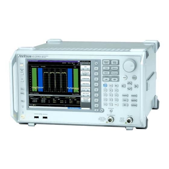
Figure 3.1.1-1 Front Panel Power Switch Press to switch between the standby state in which AC power is supplied and the Power On state in which the MS2690A/MS2691A/MS2692A is under operation. The Power lamp lights up orange in the standby state, and lights up green in the Power On state. -
Page 93: Part Names
Press to return to local operation from remote control operation through GPIB, Ethernet or USB (B), and enable panel settings. Remote lamp Lights up when the MS2690A/MS2691A/MS2692A is in a remote control state. Preset key Resets parameters to their initial settings. - Page 94 Chapter 3 Common Operations [11] Main function keys 1 Used to set or execute main functions of the MS2690A/MS2691A/ MS2692A. Executable functions vary depending on the application currently selected. Press to set parameters related to frequency. Press to set parameters related to level.
- Page 95 18 GHz or more. [17] RF output control key If the MS2690A/MS2691A/MS2692A Option 020 Vector Signal Generator is installed, pressing enables (On) or disables (Off) the RF signal output. The lamp of the RF output control key lights up orange when the...
- Page 96 Chapter 3 Common Operations [18] RF output connector (if MS2690A-020/MS2691A-020/MS2692A-020 installed) Outputs an RF signal. [19] USB connector (type A) Used to connect a USB keyboard or mouse or the USB memory supplied with the MS2690A/MS2691A/MS2692A.
- Page 97 Inputs an external reference frequency signal (10 MHz or 13 MHz). It is used for inputting reference frequency signals with accuracy higher than that of those inside the MS2690A/MS2691A/MS2692A, or for synchronizing the frequency of the MS2690A/MS2691A/MS2692A to that of other device.
- Page 98 (optional) and inputting a baseband clock reference signal of the MS2690A-020/MS2691A-020/MS2692A-020 Vector Signal Generator (optional). See Table 3.1.1-1 for the internal pin assignment of the AUX connector. GPIB connector Used when controlling the MS2690A/MS2691A/MS2692A externally via GPIB. USB connector (type B) Used when controlling the MS2690A/MS2691A/MS2692A externally via USB.
- Page 99 Part Names [12] AC inlet Used for supplying power. Table 3.1.1-1 Pin assignment of AUX connector Function Pin Number Signal Name BER_CLK BER_EN BER_DATA MARKER1 MARKER3 PULS_MOD BB_REF_CLK MARKER2 Do not connect anything to connectors not listed in Table 3.1.1-1, because they are interface connectors provided for device maintenance.
-
Page 100: Turning Power On/Off
Press the power switch. The lamp lights up green and startup begins. Turning the power On starts Windows then the MS2690A/MS2691A/ MS2692A software. The following startup screen is displayed during startup. Do not press the power switch while the startup screen is displayed. -
Page 101: Turning Power Off
A failure may have occurred in the event the power cannot be turned Off even after pressing the power switch for 4 or more seconds. Unplug the power cord from the outlet and contact an Anritsu Service and Sales office or agent. ... -
Page 102: Auto Calibration
Chapter 3 Common Operations 3.3 Auto Calibration An auto calibration function that uses an internal calibrating oscillator is provided to minimize measurement errors of the MS2690A/MS2691A/ MS2692A. CAUTION Do not input signals to RF input when calibrating. Correct calibration values cannot be obtained when the auto calibrating function is executed while signals are being input. - Page 103 Auto Calibration Page 1 Page 2 Figure 3.3-2 Cal function menu Table 3.3-1 Description of Cal function menu Menu Display Function Page 1 SIGANA Executes all calibrations (Level Cal, Band Cal, Local Leak Suppression) except Extra Band Cal. Level Executes level calibration. Band Executes analysis band calibration.
- Page 104 Chapter 3 Common Operations The auto calibration function in Page 1 includes the following four calibration functions and a function to execute functions (1) to (3) at one time. (1) Level calibration (Level Cal) Calibrates reference level errors, RBW switching errors and input attenuator switching errors to minimize level measurement errors.
- Page 105 Auto Calibration (4) Extra Band Cal Executes analysis bandwidth calibration within the current center frequency. Example: Executing analysis bandwidth calibration within the current center frequency. <Procedure> Press (Cal). Select (Extra Band Cal). When Extra Band Cal is executed, the obtained calibration value is held separately for each center frequency at the time of execution.
- Page 106 (8) to delete the values calibrated by (6) and (7). (6) SG I/Q Cal (7) SG External I/Q Cal (8) SG I/Q Cal Restore Default For details, see Section 2.9 “Auto Calibration” in MS2690A/MS2691A/MS2692A Signal Analyzer Option 020: Vector Signal Generator Operation Manual (Mainframe Operation) 3-16...
-
Page 107: Settings On Configuration Screen
Settings on Configuration Screen 3.4 Settings on Configuration Screen MS2690A/MS2691A/MS2692A system settings, and settings for system information display and common application functions can be configured in the Configuration screen. Press to display the Configuration screen. Figure 3.4-1 Configuration screen 3-17... -
Page 108: Display Description
3.4.3 “Copy Settings” Sets buzzer On/Off. System Settings 3.4.4 “System Settings” Sets loading/unloading of applications. Application Switch Settings 3.4.5 “Application Switch Settings” Displays MS2690A/MS2691A/MS2692A system System information. Information 3.4.6 “System Information” Displays options installed in the Option MS2690A/MS2691A/ MS2692A. Information 3.4.7 “Option Information”... -
Page 109: Interface Settings
Select the item to be set with the cursor, and then press (Set) to reflect the settings of that item. MS2690A/MS2691A/ Refer to Section 1.3 “Interface Settings” in the MS2692A and MS2830A/MS2840A Signal Analyzer Operation Manual (Mainframe Remote Control) for details. -
Page 110: Copy Settings
Chapter 3 Common Operations 3.4.3 Copy Settings Pressing (Copy Settings) after displays the Copy Settings screen. Screen hard copy conditions can be set in this screen. Select the item to be set with the cursor, and then press (Set) to reflect the settings of that item. -
Page 111: System Settings
Settings on Configuration Screen 3.4.4 System Settings Pressing (System Settings) after displays the System Settings screen. Select the item to be set with the cursor, and then press (Set) to reflect the settings of that item. Figure 3.4.4-1 System Settings screen Table 3.4.4-1 System Settings items Item Description... - Page 112 If using the Board Revision of IF Local Board Revision with 3 or less, and also using the 13 MHz external reference versions, contact an Anritsu Service and Sales office immediately. Contact information can be found on the last page of the printed version of this manual, and is available in a separate file on the CD version.
-
Page 113: Application Switch Settings
Settings on Configuration Screen 3.4.5 Application Switch Settings Pressing (Application Switch Settings) after displays the Application Switch Settings menu. The loading/unloading of applications can be set from this menu. Select the item to be set with the cursor, and then press (Set) to display the setting window of that item or start performing the setting. -
Page 114: System Information
3.4.6 System Information Pressing (System Information) after displays the System Information menu. The MS2690A/MS2691A/MS2692A system information can be viewed from this menu. Pressing the function key corresponding to the system information to be viewed displays the window of the selected item. - Page 115 ATT02:4dB View ATT03:8dB ATT04:10dB ATT05:16dB ATT06:20dB Displays the version of the software Software Version installed in the MS2690A/MS2691A/ View MS2692A. Displays the FPGA version for each board FPGA Version installed in the MS2690A/MS2691A/ View MS2692A. Displays the revisions of each board...
-
Page 116: Option Information
Chapter 3 Common Operations 3.4.7 Option Information Pressing (Option Information) after displays the option screen. Information on options installed in the MS2690A/MS2691A/MS2692A can be viewed in this screen. 3.4.8 File Operation Pressing (File Operation) after displays the File Operation menu. Data files can be managed from this menu. Pressing the function key corresponding to the data file to be managed displays the setting window of that item. -
Page 117: Software Install/Uninstall
2 of the System Information menu displays the Software Install menu. Software can be installed and uninstalled to/from the MS2690A/MS2691A/MS2692A from this menu. Pressing the function key corresponding to the item to be set executes the selected item. - Page 118 Chapter 3 Common Operations Pressing (Correction) on page 2 of Correction function menu after displays Correction function menu. Those functions are used to set correction factors for frequency characteristics. Figure 3.4.10-1 Correction function menu Table 3.4.10-1 Items of Correction Item Description Sets Correction to On/Off.
- Page 119 When File Name Setting is set to Data + sequential, the file is automatically named ”Corr date_sequential number”. The Save Correction Table file is in CSV format and is saved in “[Selected drive]:\Anritsu Corporation\Signal Analyzer\User Data\Corrections\”. Up to 1000 files can be saved in the folder. Close Returns to the Configuration menu.
- Page 120 Chapter 3 Common Operations Pressing (Recall Correction Table) on Correction function menu displays the Recall Correction Table function menu. Those functions are used to recall the saved level frequency characteristics. Figure 3.4.10-3 Recall Correction Table function menu Table 3.4.10-3 Items of Recall Correction Table Item Description Device...
- Page 121 Settings on Configuration Screen Describe the frequency and level to be corrected within the following range for the CSV file. Up to 4096 items of correction data can be set. [Frequency] Range –1 to 400 GHz Resolution 1 Hz Set the unit in Hz. [Level] Range –100 to 100 dB Resolution...
- Page 122 Chapter 3 Common Operations Correction factors apply to all the applications other than Signal Generator, BER Test, and RNC Simulator. In Signal Analyzer functions, the correction factors of the center frequency are applied to all the trace data in the same span. Executing the following functions initializes the correction factors.
-
Page 123: Display Annotation
Settings on Configuration Screen 3.4.11 Display Annotation When Display Annotation is OFF, the measurement target’s frequency and level included in the frequency-related settings, level-related settings, marker values, and measurement results are hidden from the application screen to avoid being seen. Press and then press . - Page 124 Chapter 3 Common Operations Table 3.4.12-1 Calibration Alert setting items Item Description Specifies the trigger conditions for alerts. None No alert occurs. Temperature An alert occurs when a temperature goes outsides the specified thresholds based on the internal temperature measured at the last automatic calibration (SIGANA All).
- Page 125 For details of remote control commands to query status, refer to “Status of Calibration Alert” in Section 4.1 “Application Common Device Messages” in the MS2690A/MS2691A/MS2692A and MS2830A/MS2840A Signal Analyzer Operation Manual (Mainframe Remote Control) 3-35...
-
Page 126: Loading, Unloading, And Switching Applications
In the event running applications are suddenly ended while operating Windows, press , turn the MS2690A/MS2691A/MS2692A power Off or shutdown Windows, and then turn the MS2690A/MS2691A/ MS2692A power On again. When many applications are running simultaneously and the measurement software calls a measurement... -
Page 127: Loading Applications
Loading, Unloading, and Switching Applications 3.5.1 Loading applications Applications can be loaded from the Configuration screen. <Procedure> After pressing , press (Application Switch Settings) to display the Application Switch Registration screen. Press (Load Application Select), select the applications to be loaded from the applications displayed in “Unloaded Applications”... - Page 128 Chapter 3 Common Operations When registered correctly, the selected applications will be displayed in “Loaded Applications” at the top part of the screen. Figure 3.5.1-2 Application Switch Registration screen Press to display the Application Switch menu. Check that the loaded application is displayed in the menu. Select the application with the function key to operate the application.
-
Page 129: Unloading Applications
Loading, Unloading, and Switching Applications 3.5.2 Unloading applications Applications can be unloaded from the Configuration screen. <Procedure> After pressing , press (Application Switch Settings) to display the Application Switch Registration screen. Press (Unload Application Select), select the application to be unloaded from the applications displayed in “Loaded Applications”... - Page 130 Chapter 3 Common Operations When ended correctly, the selected applications will be displayed in “Unloaded Applications” at the bottom part of the screen. Figure 3.5.2-2 Application Switch Settings screen 3-40...
-
Page 131: Switching Applications
Loading, Unloading, and Switching Applications 3.5.3 Switching applications Applications to be operated can be switched in the Application Switch menu. Pressing displays the Application Switch menu screen. Pressing the function key corresponding to the application to be switched switches to the selected application screen. Note: When Display Annotation is Off, only applications that support Display Annotation function are displayed in the Application Switch... -
Page 132: Changing Application Layout
Chapter 3 Common Operations 3.5.4 Changing application layout The layout of applications can be changed as desired in the Application Switch menu. Set the application layout in the Configuration screen. <Procedure> After pressing , press (Application Switch Settings) to display the Application Switch Registration screen. Press (Position Change) to display the Application Switch Function Position Edit screen. - Page 133 Loading, Unloading, and Switching Applications Select the layout position from the slots in the Function Position field with the cursor, and then press After checking that the application is placed in the selected position, press (Set). Figure 3.5.4-2 Application Switch Function Position Edit screen 3-43...
-
Page 134: Save And Recall Functions
USB memory (Parameter) and saving (Save) and recalling (Recall) of waveform data (Trace). Note: Use the USB memory supplied with the MS2690A/MS2691A/ MS2692A. Using other USB memories may cause malfunction due to device incompatibility. 3.6.1 Saving parameters and waveform data... - Page 135 3.4.3 “Copy Settings” Files will be saved in the following directory of the save target drive specified in (Device). \Anritsu Corporation\Signal Analyzer\User Data\Trace Data The maximum number of files in one folder is: Signal Analyzer: 1000 Spectrum Analyzer: 100 3-45...
-
Page 136: Recalling Parameters
Chapter 3 Common Operations 3.6.2 Recalling parameters With the MS2690A/MS2691A/MS2692A, settings can be restored by loading saved setting conditions from the internal hard disk or a USB memory. Recalling parameter setting conditions only of applications to be operated using Application Switch <Procedure>... - Page 137 Save and Recall Functions Figure 3.6.2-1 Recall menu 3-47...
-
Page 138: Screen Hard Copy
A sequential number from 000 to 999 will be added to the file name. Files will be saved in the following directory of the save target drive specified in (Device). \Anritsu Corporation\Signal Analyzer\User Data\Copy Files Up to 1000 files can be saved in the folder. 3-48... -
Page 139: Simple Save&Recall
Save and Recall Functions 3.6.4 Simple Save&Recall This function allows parameter setting conditions to be recalled with little operations. Enabling Simple Save&Recall: <Procedure> Press to display the Configuration screen. Press to display page 2 of the Configuration screen. Press (Save&Recall Settings) to display the Save&Recall Settings menu in Figure 3.6.4-1. - Page 140 Chapter 3 Common Operations Changing the parameter name (file name) to be saved from the default setting Pressing (Simple Save&Recall Name) in Figure 3.6.4-1 displays the Simple Save&Recall Name menu in Figure 3.6.4-2. Up to ten parameter names can be registered in Simple mode. The default parameter names are PRM_1 to PRM_10.
- Page 141 Read-only. Pressing the function key stores the parameter saving file with the parameter name displayed. \Anritsu Corporation\Signal Analyzer\User Data\Parameter Setting The parameter settings can be saved in Standard mode on Open Save Menu. 3.6.1 “Saving parameters and waveform data”...
- Page 142 Chapter 3 Common Operations Simple Recall function Pressing the image of Recall button in Simple mode displays the Simple Recall menu in Figure 3.6.4-4. Figure 3.6.4-4 Simple Recall menu Parameter names set with the Simple Save&Recall Name menu are displayed on the function keys. The last saved date and time of the parameter saving file is displayed in the second line.
-
Page 143: Initializing
Initializing 3.7 Initializing This section describes how to initialize settings. 3.7.1 Preset Preset is a function for initializing application settings. Configuration screen settings are not initialized using this function. Similarly, there is no effect on user data saved to the internal hard disk. <Procedure>... -
Page 144: System Reset
Press (System Information) and then press to display page 2 of the System Information menu. Press (System Reset) to execute System Reset. The MS2690A/MS2691A/MS2692A restarts automatically when System Reset is completed. Figure 3.7.2-1 System Information menu (2 of 2) 3-54... -
Page 145: Installing And Uninstalling
(e.g., “E:\” when the USB memory is drive E). Click [OK] to copy the installation data into the USB memory. The installation data is copied into the “E:\Anritsu Corporation\Signal Analyzer\Install” folder, when the USB memory is drive E. - Page 146 Chapter 3 Common Operations Installing software <Procedure> Remove the peripheral devices from the USB ports of the MS2690A/MS2691A/MS2692A, other than mouse and keyboard. Press to display the Configuration screen, and then press (Software Install) from page 2 of the Configuration menu.
- Page 147 Installing and Uninstalling Figure 3.8.1-1 Software Install menu 3-57...
- Page 148 When pressing (Install), a message box asking "Do you install the selected application software license?" is displayed. Press Yes to start installation. The license becomes valid when the MS2690A/MS2691A/MS2692A is restarted after installation is completed. Figure 3.8.1-2 Software Install menu 3-58...
- Page 149 (Install), a message box asking "Do you install the selected SG Waveform license?" is displayed. Press Yes to start installation. The license will be valid when the MS2690A/MS2691A/MS2692A is restarted after installation is completed. Figure 3.8.1-3 Software Install menu 3-59...
-
Page 150: Uninstalling Software
Chapter 3 Common Operations 3.8.2 Uninstalling software The Install screen must be displayed in order to uninstall software or license files from the MS2690A/MS2691A/MS2692A. Uninstalling software <Procedure> Press to display the Configuration screen, and then press (Software Install) from page 2 of the Configuration menu. - Page 151 Installing and Uninstalling Uninstalling software licenses <Procedure> Press to display the Configuration screen, and then press (Software Install) from page 2 of the Configuration menu. The Software Install menu shown in Figure 3.8.2-2 is displayed. Press (Uninstall). The installation selection menu is displayed. Press (Software License).
- Page 152 Chapter 3 Common Operations Uninstalling waveform pattern licenses <Procedure> Press to display the Configuration screen, and then press (Software Install) from page 2 of the Configuration menu. The Software Install menu shown in Figure 3.8.2-3 is displayed. Press (Uninstall). The installation selection menu is displayed. Press (SG Wave License).
-
Page 153: Chapter 4 Tutorial
Chapter 4 Tutorial This chapter describes the waveform display of the signal analyzer and spectrum analyzer. Spectrum Analysis Using Signal Analyzer ....4-2 4.1.1 Spectrum analysis ..........4-2 Spectrum Analysis Using Spectrum Analyzer ....4-7 4.2.1 Spectrum Analysis ..........4-7... -
Page 154: Spectrum Analysis Using Signal Analyzer
Chapter 4 Tutorial 4.1 Spectrum Analysis Using Signal Analyzer 4.1.1 Spectrum analysis The section describes the operation procedure for outputting input signal waveforms to the application screen of the signal analyzer. Input signal Figure 4.1.1-1 Front panel Example: Input Signal: Frequency: 1 GHz (CW) Level: 10 dBm... - Page 155 Spectrum Analysis Using Signal Analyzer <Procedure> Connect the input signal to the RF Input (N-type connector) on the front panel of the MS2690A/MS2691A/MS2692A. Press then (Application Switch Settings) to display the Application Switch Settings menu. Press (Load Application Select) to select within the “Unload Applications”...
- Page 156 Chapter 4 Tutorial Table 4.1.1-1 Display items for Signal Analyzer Item Description This is the main function key of the signal analyzer. Basic parameter settings of the signal analyzer are configured here. Signal Analyzer Function Operation 2.1 “Display Description” Displays signal waveforms. Displays the center frequency, frequency span and other frequency parameters.
- Page 157 Spectrum Analysis Using Signal Analyzer Enter the center frequency then select the unit, from GHz, MHz, kHz, and Hz. Example: To set 1 GHz for the center frequency, press and then (GHz). The waveform of the input signal is now displayed on the screen (see Figure 4.1.1-5).
- Page 158 Chapter 4 Tutorial Figure 4.1.1-5 Waveform display using Signal Analyzer Refer to the MS2690A/MS2691A/MS2692A Signal Analyzer Operation Manual (Signal Analyzer Function Operation) for how to use the Signal Analyzer.
-
Page 159: Spectrum Analysis Using Spectrum Analyzer
Spectrum Analysis Using Spectrum Analyzer 4.2 Spectrum Analysis Using Spectrum Analyzer 4.2.1 Spectrum Analysis This section describes the operation procedure for outputting input signal waveforms to the application screen of the spectrum analyzer. Input signal Figure 4.2.1-1 Front panel Example: Input Signal: Frequency: 1 GHz (CW) Level: 10 dBm... - Page 160 Chapter 4 Tutorial <Procedure> Connect the input signal to the RF Input (N-type connector) on the front panel of the MS2690A/MS2691A/MS2692A. Press then (Application Switch Settings) to display the Application Switch Settings menu. Press (Load Application Select) to select within the “Unload Applications”...
- Page 161 Spectrum Analysis Using Spectrum Analyzer Table 4.2.1-1 Display items for Spectrum Analyzer Item Description This is the main function key of the spectrum analyzer. Basic parameter settings of the spectrum analyzer are configured here. Spectrum Analyzer Function Operation 2.1 “Display Description” Displays signal waveforms.
- Page 162 Chapter 4 Tutorial Enter the center frequency then select the unit, from GHz, MHz, kHz, and Hz. Example: To set 1 GHz for the center frequency, press and then (GHz). Figure 4.2.1-4 Spectrum analyzer main function menu 4-10...
- Page 163 11. Enter the frequency bandwidth then select the unit of the value. The waveform of the input signal is now displayed on the screen (see Figure 4.2.1-5). Figure 4.2.1-5 Waveform display using Spectrum Analyzer MS2690A/MS2691A/MS2692A Signal Analyzer Operation Refer to the Manual (Spectrum Analyzer Function Operation) for how to use the Spectrum Analyzer.
- Page 164 Chapter 4 Tutorial 4-12.
-
Page 165: Chapter 5 System
Chapter 5 System The MS2690A/MS2691A/MS2692A uses Microsoft Windows (hereinafter, referred to as “Windows”) as the operating system. Settings for Windows and the system can be operated by connecting a mouse and a keyboard. This chapter describes how to perform operations on Windows installed to the MS2690A/MS2691A/MS2692A and general notes. -
Page 166: Setting Windows
Chapter 5 System 5.1 Setting Windows The MS2690A/MS2691A/MS2692A is set to default settings at factory shipment so as to perform optimal measurements. Changing the Windows settings is outside the scope of operation warranty. In addition, performance may drop or functions may not operate correctly when Windows settings are changed. -
Page 167: Displaying Windows Desktop
Windows Taskbar. Mouse Click the “Minimize” button located in the upper right corner of the application window of the MS2690A/MS2691A/MS2692A. Minimizing all applications displays the Desktop. Keyboard Pressing the [Windows] key + [D] key minimizes all windows and... -
Page 168: Setting Control Panel
• Anritsu does not warrant operations of MS2690A/MS2691A/MS2692A when programs not guaranteed are installed. Windows Update • Automatic updating of Windows is turned off at the factory. Anritsu does not warrant operations of MS2690A/MS2691A/MS2692A when the setting is changed. Network Connection •... - Page 169 On, Windows Firewall displays a dialog box asking if you want to block the applications of MS2690A/MS2691A/MS2692A at the next startup time. Be sure to click Unblock. • Antivirus software is not installed at the factory. Anritsu strongly recommends installing antivirus software when connecting MS2690A/MS2691A/MS2692A to a network. However, MS2690A/MS2691A/MS2692A may not be remote-controlled through Ethernet if the function blocking external communications works.
-
Page 170: Using External Display
5.1.3 Using external display An external display can be connected to the VGA connector on the rear side of the MS2690A/MS2691A/MS2692A, to display screens of the MS2690A/MS2691A/MS2692A and show multiple displays. The following describes the operation procedure for this function. - Page 171 Setting Windows When the OS on MS2690A/MS2691A/MS2692A is Windows Embedded Standard 7 <Procedure> Connect the display to the VGA connector on the rear of MS2690A/MS2691A/MS2692A. Open the Intel Graphics and Media Control Panel by one of the following methods: •...
-
Page 172: General Notes
Install antivirus software and execute virus scan. • Enable or operate a Windows program service that is disabled or stopped at factory. e.g.) Transfer files by FTP while the MS2690A/MS2691A/MS2692A is running. In addition to the above, note the below. -
Page 173: Storage Device Configuration
• Do not change the partition configuration. Doing so may affect system operation. • Do not format the hard disk of the MS2690A/MS2691A/MS2692A. Besides the above, data for system recovery is stored within this hard disk. Recovery may become inoperable when the hard disk is formatted. -
Page 174: System Recovery Functions
Connect the keyboard and mouse to the mainframe, and then turn the MS2690A/MS2691A/MS2692A power On. The BIOS screen will appear in a few seconds after (The message “Press F2 for System Utilities” appears at the bottom part of the screen). - Page 175 System Recovery Functions CAUTION To execute these functions, understand the following items for their use. • All applications and updates added after factory shipment will be lost. Additionally, all data recorded to Volume C will be restored to the factory shipment status. Backup important data before executing these functions.
- Page 176 “Phoenix Recover Pro”. Restore System drive (partition) only This function restores only Volume C, in which Windows, application software, and files required for operations of the MS2690A/MS2691A /MS2692A are stored, to the factory shipment status. Restore entire hard disk This function restores Volume C and Volume D to the factory shipment status.
- Page 177 “Paragon Drive Backup”. Type: Partition This function restores only Volume C, in which Windows, application software, and files required for operations of the MS2690A/MS2691A /MS2692A are stored, to the factory shipment status. Type: Disk This function restores Volume C and Volume D to the factory shipment status.
- Page 178 Chapter 5 System When the completion screen appears, click [Finish] to return to the menu screen described in Step 5. Click [Reboot the computer] to reboot the MS2690A/MS2691A/MS2692A, or click [Power off] to turn the power Off. 5-14.
-
Page 179: Chapter 6 Performance Test
Chapter 6 Performance Test This chapter describes measurement devices, setup methods, and performance test procedures required for performing performance tests as preventive maintenance of the MS2690A/MS2691A/MS2692A. Overview of Performance Test ........6-2 6.1.1 Performance test ..........6-2 6.1.2 Performance test items and instruments used . 6-3 Performance Test Items .......... -
Page 180: Overview Of Performance Test
If items that do not meet the required level are detected during performance testing, contact an Anritsu Service and Sales office. Contact information is available in a separate file (for the PDF version), and on the last page of this manual (for the printed version). -
Page 181: Performance Test Items And Instruments Used
1 Hz resolution available Display frequency accuracy MG3692C is also available Output level range: 20 to 0 dBm for MS2690A and MS2691A. 0.1 dB resolution available With Option 004 or 005. Frequency range: 3,000 to 23,850 MHz Signal generator... - Page 182 Chapter 6 Performance Test Table 6.1.2-1 List of measuring instruments for performance test (Cont’d) Name of Recommended Test Items Required Performance Device (Model Name) Signal generator (MG3710A) Less than 6 GHz Frequency range: 250 kHz to 13.5 GHz 1 Hz resolution available Signal generator (MG3693C/94C) ...
-
Page 183: Performance Test Items
Performance Test Items 6.2 Performance Test Items Warm up the subject testing device and measuring instruments for at least 30 minutes except where directed, in order to stabilize them sufficiently before running performance tests. Demonstrating maximum measurement accuracy requires, in addition to the above, conducting performance tests under ambient temperatures, little AC power supply voltage fluctuations, as well as the absence of noise, vibrations, dust, humidity or other problems. -
Page 184: Display Frequency Accuracy
6.2.1 Display frequency accuracy The known frequency which is the reference for the display frequency, is added to the MS2690A/MS2691A/MS2692A as shown in (3) then the center frequency and frequency span are set from the front panel. The difference between the read value of the marker display frequency (bold... - Page 185 Set the frequency span (10 kHz) and the resolution bandwidth (300 Hz) corresponding to the center frequency (500 MHz) shown in the Display Frequency Accuracy table of Appendix A to the MS2690A/ MS2691A/MS2692A. Read the marker frequency value (MKR value) shown on the screen,...
-
Page 186: Frequency Span Display Accuracy
(1) Test target standards MS2690A/MS2691A/MS2692A Frequency span accuracy: 0.2% (2) Measuring instrument for tests Signal generator (MG3693C/94C) (MG3692C is also available for MS2690A and MS2691A) (3) Setup Frequency measured with SG Buffer Out Ref Input MS2690A/MS2691A/ 10 MHz... - Page 187 (4) Notes on test Although the output level of the MG3693C/94C is not specified, set normally to 10 to 0 dBm. (5) Test procedure Press of the MS2690A/MS2691A/MS2692A then select the Spectrum Analyzer. Press of the MS2690A/MS2691A/MS2692A. Press (Preset) to perform Preset.
-
Page 188: Single Sideband Noise Level
Chapter 6 Performance Test 6.2.3 Single sideband noise level Set the resolution bandwidth to a specific value then input a signal with a single sideband noise level far smaller than the subject test device. Test how far the dB drops from the peak point for a noise level which is distanced by a specific frequency from the spectrum waveform peak point at this time. - Page 189 Set as follows for the MS2690A/MS2691A/MS2692A: Reference level 0 dBm Attenuator 0 dB Span frequency 0 Hz VBW mode Power Det mode Sample 100 Hz 1 Hz Sweep time Trace points 1001 Set the center frequency of the MS2690A/MS2691A/MS2692A to 2 GHz. 6-11...
- Page 190 [p0]. Start time 0.1 s Stop time 0.9 s For the MS2690A/MS2691A/MS2692A, set the center frequency (2.0001 GHz) corresponding to the offset frequency (100 kHz) shown in the Single Sideband Noise Level table of Appendix A. Also, set RBW to 10 kHz according to this table.
-
Page 191: Rf Frequency Characteristics
MS2690A Frequency characteristics After CAL execution, at input attenuator = 10 dB, 18 to 28C (Without MS2690A-008 or Preamplifier=OFF) 0.35 dB (9 kHz frequency 6 GHz, Frequency Band Mode: Normal) (With MS2690A-008 and Preamplifier=ON) 0.65 dB (100 kHz frequency 6 GHz, Frequency Band Mode: Normal) ... - Page 192 (13.5 GHz frequency 26.5 GHz) (2) Measuring instrument for tests Signal generator (MG3710A) [Less than 6 GHz] Signal generator (MG3693C/MG3694C) [6 GHz or more] (MG3692C is also available for MS2690A and MS2691A) Power meter (ML2488A) Power sensor (MA2421D) [Less than 6 GHz] ...
- Page 193 Performance Test Items (3) Setup Buffer Out Ref Input 10 MHz 10 MHz MS2690A/MS2691A/ MG3710A or MG3693C/94C MS2692A RF Output RF Input Attenuator Attenuator (3 dB) (3 dB) Power meter (ML2488A) Anritsu MS2487A Power sensor (MA2421D or MA2444D) At initial setup, connect the MG3710A and MA2421D.
- Page 194 MG3710A (MG3693C/94C) and the indicated value (calibration value) on the power meter. Measuring RF frequency characteristics Connect the MG3710A (MG3693C/94C) RF output to the RF input of the MS2690A/MS2691A/MS2692A using the coaxial cable. Start the application Spectrum Analyzer of the MS2690A/MS2691A/MS2692A.
- Page 195 RF Frequency Characteristics table of Appendix A. 10. Calculate the RF frequency characteristics, using the calibration value of the MG3710A (MG3693C/94C) and the indicated value on the MS2690A/MS2691A/MS2692A. RF frequency characteristics = Indicated value on MS2690A/MS2691A/MS2692A – calibration value (indicated value on power meter) 11.
-
Page 196: Display Average Noise Level
155 dBm/Hz (30 MHz frequency 2.4 GHz) 153 dBm/Hz (2.4 GHz frequency 4 GHz) 152 dBm/Hz (4 GHz frequency 6 GHz) (With MS2690A-008 or Preamplifier=ON) 150 dBm/Hz (100 kHz) 159 dBm/Hz (1 MHz) ... - Page 197 Performance Test Items (With MS2691A-008 or Preamplifier=ON) 150 dBm/Hz (100 kHz) 159 dBm/Hz (1 MHz) 166 dBm/Hz (30 MHz frequency 2.4 GHz) 165 dBm/Hz (2.4 GHz frequency 3 GHz) 164 dBm/Hz (3 GHz frequency 4 GHz) ...
- Page 198 Chapter 6 Performance Test 151 dBm/Hz (3 GHz frequency 4 GHz) 150 dBm/Hz (4 GHz frequency 5 GHz) 149 dBm/Hz (5 GHz frequency < 6 GHz) 151 dBm/Hz (6 GHz frequency < 10 GHz) ...
- Page 199 Performance Test Items (3) Setup Standard Terminator (Terminates RF Input) Figure 6.2.5-1 Display average noise level (4) Notes on test Perform the test at an ambient temperature of 18 to 28C and after warming up for at least 30 minutes. 6-21...
- Page 200 Chapter 6 Performance Test (5) Test procedure Start the application Spectrum Analyzer of the MS2690A/MS2691A/ MS2692A. Press of the MS2690A/MS2691A/MS2692A. Press (Preset). Press and then (SIGANA All). Terminate the RF input with the standard terminator. Set as follows for the MS2690A/MS2691A/MS2692A (time domain mode).
-
Page 201: Second Harmonic Wave Distortion
In the event a low distortion signal source cannot be obtained, apply a low distortion signal to the MS2690A/ MS2691A/MS2692A after passing through LPF. (1) Test Target Standards ... - Page 202 (4) Notes on test Perform the test at an ambient temperature of 18 to 28C and after warming up for at least 30 minutes. (5) Test procedure Start the application Spectrum Analyzer of the MS2690A/MS2691A/ MS2692A. Press of the MS2690A/MS2691A/MS2692A.
- Page 203 Performance Test Items Adjust the output level of the signal generator so as to get the peak point of the spectrum waveform into the range of 20 dBm 0.06 dB. 10. Press to perform a peak search. Set so as to include the signal trace peak point to the zone marker.
- Page 204 Chapter 6 Performance Test 12. In order to display the second harmonic wave on the screen, set twice as much frequency as the center frequency. Delta marker level reading indicates the level difference between the fundamental wave and the second harmonic wave. In the event the level difference is 80 dB or higher, set the reference level to 50 dBm.
-
Page 205: Chapter 7 Power Meter
Chapter 7 Power Meter This chapter describes basic operations of the power meter functions. Power Meter ..............7-2 Display Description ............7-3 Function Menu .............. 7-5 7.3.1 Setting the frequency........7-6 7.3.2 Level setting ............. 7-7 7.3.3 Measure ............7-9 7.3.4 Accessory ............ -
Page 206: Power Meter
Section 3.8 “Installing and Uninstalling” and Section 3.5 “Loading, Unloading, and Switching Applications.” The MS2690A/MS2691A/MS2692A can accept any USB power sensor in the following table, automatically recognize its model name, and automatically set the COM Port regardless of the USB Port to which the USB power sensor is connected. -
Page 207: Display Description
Display Description 7.2 Display Description Press to display the Application Switch function menu. Then, select the Power Meter, and you can display the power meter application main screen and the function menu. Figure 7.2-1 Power meter application main screen... -
Page 208: Display Description
Chapter 7 Power Meter Table 7.2-1 Parameters on the power meter application main screen Display Description Application software name Power Meter The name of the synchronizing application is displayed in parentheses. COM Port number (xx) to which the USB COMxx power sensor is connected. -
Page 209: Function Menu
Function Menu 7.3 Function Menu Press when the Power Meter function to display the Power Meter function menu. Table 7.3-1 Power Meter function menu Function Menu Display Function Opens the Frequency function menu. Frequency 7.3.1 “Setting the frequency” Opens the Amplitude function menu. Amplitude 7.3.2 “Level setting”... -
Page 210: Function Menu
Chapter 7 Power Meter 7.3.1 Setting the frequency In the Frequency function menu, you can set the calibration factor frequency of the USB power sensor. Press (Frequency) in the Power Meter function menu to display the Frequency function menu. Table 7.3.1-1 Frequency function menu Function Menu Display Function... -
Page 211: Level Setting
Function Menu 7.3.2 Level setting Press (Amplitude) or in the Power Meter function menu to display the Amplitude function menu. Table 7.3.2-1 Amplitude function menu Function Menu Display Function Range Opens the Range function menu. Offset Turns on and off the level offset function. (On/Off) Offset Value Sets the level offset value. - Page 212 When this function is used, the displayed power sensor value is offset with the value specified in the Offset Value dialog box. It is used when the path loss or gain from the MS2690A/MS2691A/MS2692A to DUT is corrected. [Power sensor reading after offset]...
-
Page 213: Measure
Function Menu 7.3.3 Measure Press (Measure) or in the Power Meter function menu to display the Measure function menu. The Measure function menu items depend on whether the Power Meter application synchronizes with the other application or not. When not synchronizing with any applications Table 7.3.3-1 Measure function menu Function Menu Display... -
Page 214: Accessory
Chapter 7 Power Meter 7.3.4 Accessory Press (Accessory) in the Power Meter function menu to display the Accessory function menu. Table 7.3.4-1 Accessory function menu Function Menu Display Function Title Sets the title character string. Turns on and off the title character Title (On/Off) string display. -
Page 215: Power Meter
Function Menu 7.3.5 Power Meter Press (Power Meter) in the Measure function menu. In the Power Meter menu, you can set the measurement that is performed by using the USB power sensor. Table 7.3.5-1 Power Meter function menu Function Menu Display Function Turns on and off the function of averaging the Average... - Page 216 (Zero Sensor) in the Power Meter function menu to execute the zeroing. When you execute the function, a progress dialog box appears. Please do not operate the MS2690A/MS2691A/MS2692A during the zeroing. Figure 7.3.5-1 “Power Meter zeroing” dialog box (Progress) If the zeroing fails, the following dialog box appears.
- Page 217 <Procedure> 1. Plug in the USB power sensor connector to the USB port of the MS2690A/MS2691A/MS2692A Signal Analyzer. Turn off the RF output of DUT (device under test) in advance. Connect the RF Input connector of the power sensor to the RF output terminal of DUT.
-
Page 218: Aperture Setting
Chapter 7 Power Meter 7.3.6 Aperture Setting Press (Aperture Setting) in the Power Meter function menu to display the Aperture Setting menu. Refer to the “Aperture Time” section and the “Measurement Considerations” section of your power sensor chapter in “USB Power Sensors MA241xxA and PowerXpert User Guide”... -
Page 219: Initialization
Initialization 7.4 Initialization 7.4.1 Preset Power Meter function is a kind of application. For the presetting procedure, refer to Section 3.7.1 “Preset.” 7.4.2 Default value list This section lists the default values of the Power Meter function. Frequency 1 GHz Level Offset State Level Offset Value 0.00 dB... -
Page 220: Installing The Driver Software
7.5 Installing the Driver Software The Found New Hardware Wizard appears when you first connect a USB power sensor to the MS2690A/MS2691A/MS2692A, when the driver software for the connected USB power sensor is not installed, or when you connect the USB power sensor to a different port. - Page 221 Installing the Driver Software Select “Install the software automatically (Recommended),” and click [Next]. “Anritsu MA24108A” in the following example shows the model name of the connected power sensor. Figure 7.5-2 Found New Hardware Wizard-2 Click [Continue Anyway] in the Hardware Installation dialog box.
- Page 222 Chapter 7 Power Meter Click [Finish] to complete the installation. “Anritsu MA24104A” in the following example shows the model name of the connected power sensor. Figure 7.5-4 Found New Hardware Wizard-3 7-18.
-
Page 223: Chapter 8 Maintenance
Chapter 8 Maintenance This chapter describes cautions related to daily maintenance, storage, and shipping of the MS2690A/MS2691A/MS2692A, as well as the calibration procedure to be used as preventive maintenance. Daily Maintenance and Storage ........8-2 8.1.1 Daily maintenance ..........8-2 8.1.2 Cautions on storage MS2690A/MS2691A/MS2692A... -
Page 224: Daily Maintenance And Storage
Panel surface dirt When surface dirt is noticeable, after the MS2690A/MS2691A/MS2692A has been used in a dusty environment, or when the MS2690A/MS2691A/ MS2692A has not been used for an extended period of time, wipe its surface with a cloth moistened in detergent and wrung enough. -
Page 225: Cautions On Storage Ms2690A/Ms2691A/Ms2692A For Extended Period
90% or higher Recommended storage conditions It is recommended that the MS2690A/MS2691A/MS2692A be stored in a place that meets the ambient conditions suggested above, plus the following conditions, if it is not to be used for a long period of time: ... -
Page 226: Storing Usb Memory Stick
Chapter 8 Maintenance 8.1.3 Storing USB memory stick Store the USB memory stick at temperatures between 4°C and 53°C and relative humidity between 8% and 90% (no condensation). Avoid storing the USB memory stick in places that are: Dusty or damp ... -
Page 227: Repackaging And Transporting When Returning Product
Repackaging and transporting when returning product 8.2 Repackaging and transporting when returning product The following describes cautions on transporting the MS2690A/MS2691A/MS2692A. Front panel guard Carrying belt Figure 8.2-1 Guard and Carrying Belt When carrying the unit, hold tightly the carrying belts on both sides. Do not use the front panel guard for moving. -
Page 228: Repackaging
Procure a corrugated cardboard, wooden, or aluminum box large enough to pack in cushioning material around the MS2690A/MS2691A/MS2692A. Place the MS2690A/MS2691A/MS2692A into the box. Then, pack in the cushioning material around the MS2690A/MS2691A/ MS2692A so that the MS2690A/MS2691A/MS2692A does not move around in the box. -
Page 229: Calibration
MS2690A/MS2691A/MS2692A’s performance from becoming degraded. Even if the MS2690A/MS2691A/MS2692A is functioning normally, calibrate it periodically to maintain its performance. Calibrating the MS2690A/MS2691A/MS2692A once or twice a year is recommended. If the MS2690A/MS2691A/MS2692A fails to meet specifications after calibration, contact an Anritsu Service and Sales office. -
Page 230: Calibrating Frequencies Using Frequency Counter
Use a frequency standard radio signal (signal synchronized with a standard radio signal or with a rubidium atom standard device) offering enough accuracy higher than the reference oscillator installed in the MS2690A/MS2691A/MS2692A. Table 8.3.3-1 Calibration specifications Reference Oscillator Aging Rate... - Page 231 (Reference In) of frequency counter. Connect the reference signal output (Buffer Out) located on the rear panel of the MS2690A/MS2691A/MS2692A to the reference signal input connector (Reference In) of Signal Generator. Connect the RF output connector 1 of signal generator to input 1 connector of the frequency counter.
- Page 232 Chapter 8 Maintenance Figure 8.3.3-2 Signal analyzer function menu 8-10.
-
Page 233: Appendix A Performance Test Result Form
Appendix A Performance Test Result Form Performance Test Result Form Test Report No. Location Date Test person in charge Equipment Name: MS2690A/MS2691A/MS2692A Signal Analyzer Serial No. Ambient °C temperature Power Relative frequency humidity Remarks... - Page 234 Appendix A Performance Test Result Form Display Frequency Accuracy MS2690A display frequency accuracy test Setting for MS2690A Minimum Reading Maximum Frequency Resolution Frequency [Hz] Frequency [Hz] Span Bandwidth [Hz] [Hz] [Hz] 1.5 G 10 k 1499999962 1500000038 200 k...
- Page 235 Appendix A Performance Test Result Form MS2692A display frequency accuracy test Setting for MS2690A Minimum Reading Maximum Frequency Resolution Frequency [Hz] Frequency [Hz] Span Bandwidth [Hz] [Hz] [Hz] 1.5 G 10 k 1499999962 1500000038 200 k 1499999420 1500000580 30 k...
- Page 236 Appendix A Performance Test Result Form Frequency Span Display Accuracy Frequency span frequency display verification test Settings for MS2690A/MS2691A/MS2692A Measurement Results Signal Generator Minimum Maximum Frequency Frequency ′ − f ′ )/0.8 Span [Hz] [Hz] [Hz] /SPAN × 100 [Hz] −...
- Page 237 Appendix A Performance Test Result Form RF Frequency Characteristics Frequency Band Mode: Normal (MS2690A/MS2691A/MS2692A) Without Preamplifier or Preamplifier=OFF Measurement Results Calibration Measured Frequency Minimum Maximum Uncertainty Value Value Measured Value- [Hz] [dB] [dB] [dB] [dBm] [dBm] Calibration Value [dB] –0.35...
- Page 238 Appendix A Performance Test Result Form Frequency Band Mode: Normal (only for MS2691A/MS2692A) Measurement Results Calibration Measured Frequency Minimum Maximum Uncertainty Value Value Measured Value- [Hz] [dB] [dB] [dB] [dBm] [dBm] Calibration Value [dB] 6.01 G –1.50 +1.50 ±0.30 –1.50 +1.50 ±0.30 10 G...
- Page 239 13499 M 13501 M 16999 M –147 19999 M 20001 M 22999 M –143 26499 M Note: 9 kHz to 5999 MHz for the MS2690A 9 kHz to 13500 MHz for the MS2691A 9 kHz to 26500 MHz for the MS2692A...
- Page 240 1999 M 2399 M 2999 M –165 3999 M –164 4999 M –161 6000 M –159 Note: 100 kHz to 6000 MHz for the MS2690A 100 kHz to 6000 MHz for the MS2691A 100 kHz to 6000 MHz for the MS2692A...
- Page 241 13499 M 13501 M 16999 M –147 19999 M 20001 M 22999 M –143 26499 M Note: 9 kHz to 5999 MHz for the MS2690A 9 kHz to 13500 MHz for the MS2691A 9 kHz to 26500 MHz for the MS2692A...
- Page 242 Appendix A Performance Test Result Form Frequency Band Mode: Spurious (Only when Option 003 is installed) Center Frequency Display Average Noise Specification Value [Hz] Level (dBm/Hz) 100 k –135 –145 30 M 99 M 999 M –155 1999 M 2399 M 2999 M –153 3001 M...
- Page 243 Appendix A Performance Test Result Form Second Harmonic Wave Distortion Second harmonic wave measurement Without Preamplifier Measurement Settings for MS2690A/MS2691A/MS2692A Results Maximum [dBc] Uncertaint [dBc] (Mixer Input Level= − 30 dBm) [dB] Frequency Ref_Level Applicable [MHz] [dBm] –10 SLP-10.7 +1.5...
- Page 244 Appendix A Performance Test Result Form A-12.
-
Page 245: Appendix B Panel Keys And Keyboard Operations
Appendix B Panel Keys and Keyboard Operations Table B-1 Correspondences between panel keys and keyboard operations Panel Key USB Keyboard [Preset] [Ctrl]+[Shift]+[R] [Top] [Ctrl]+[Shift]+[↑] [F1] [F1] [F2] [F2] [F3] [F3] [F4] [F4] [F5] [F5] [F6] [F6] [F7] [F7] [F8] [F8] [Back] [Ctrl]+[Shift]+[←] [More]... - Page 246 Appendix B Panel Keys and Keyboard Operations Table B-1 Correspondences between panel keys and keyboard operations (Cont’d) Panel Key USB Keyboard [ . ] [ . ] [+/-] [ - ] [Shift] [Shift]+ [Cancel] [Esc] [BS] [Back Space] [Single] [Ctrl]+[Shift]+[F1] [Continuous] [Ctrl]+[Shift]+[F2] [Frequency]...
- Page 247 Index References are to page numbers. Symbol and Numbers Elapsed Time ..........3-34 Enter key ............3-5 AC inlet............. 3-9 Ethernet ..........3-3, 3-19 Accessory ............7-10 Ethernet connector ........... 3-8 Alert Mode ............3-34 External display ..........5-6 Amplitude ............7-7 Extra Band Cal ........
- Page 248 Index SG External I/Q Cal ........3-13 SG I/Q Cal ............3-13 Main function keys .......... 3-4 SG Wave License ........3-59, 3-62 Monitor Out connector........3-8 SG Wave License View ........3-25 Shift key ............3-5 SIGANA All ............. 3-13 Numeric keypad ..........
-
Page 249: Index
Index Zeroing ............7-12 Index-3... - Page 250 Index Index-4.
Need help?
Do you have a question about the MS2690A and is the answer not in the manual?
Questions and answers