Table of Contents
Advertisement
Quick Links
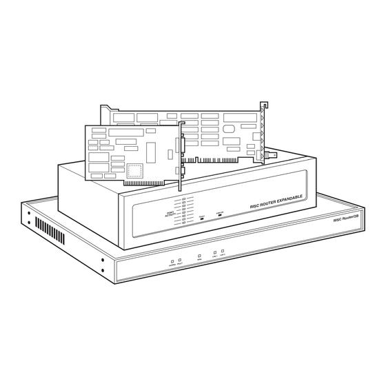
RISC Router Expandable
CUSTOMER
SUPPORT
INFORMATION
P O R T
IT Y
A C T IV
Order toll-free in the U.S.: Call 877-877-BBOX (outside U.S. call 724-746-5500)
FREE technical support 24 hours a day, 7 days a week: Call 724-746-5500 or fax 724-746-0746
Mailing address: Black Box Corporation, 1000 Park Drive, Lawrence, PA 15055-1018
Web site: www.blackbox.com • E-mail: info@blackbox.com
1
2
R I S C
3
4
O N
5
P W R
6
F A U LT
7
8
DECEMBER 1993
E
D A B L
X P A N
E R E
R O U T
LR5000A
Advertisement
Table of Contents

Related Manuals for Black Box LR5000A


Summary of Contents for Black Box LR5000A
- Page 1 Order toll-free in the U.S.: Call 877-877-BBOX (outside U.S. call 724-746-5500) SUPPORT FREE technical support 24 hours a day, 7 days a week: Call 724-746-5500 or fax 724-746-0746 INFORMATION Mailing address: Black Box Corporation, 1000 Park Drive, Lawrence, PA 15055-1018 Web site: www.blackbox.com • E-mail: info@blackbox.com...
- Page 3 FCC AND IC RFI STATEMENT FEDERAL COMMUNICATIONS COMMISSION INDUSTRY CANADA RADIO FREQUENCY INTERFERENCE STATEMENTS This equipment generates, uses, and can radiate radio frequency energy and if not installed and used properly, that is, in strict accordance with the manufacturer’s instructions, may cause interference to radio communication. It has been tested and found to comply with the limits for a Class A computing device in accordance with the specifications in Subpart J of Part 15 of FCC rules, which are designed to provide reasonable protection against such interference when the equipment is...
-
Page 4: Table Of Contents
RISC ROUTER EXPANDABLE Contents 1.0 SPECIFICATIONS ..................3 2.0 INTRODUCTION..................4 General Description................4 Front-Panel Components ...............6 Back-Panel Components..............7 RISC Bridge/E Expansion Card ..........10 3.0 INSTALLATION..................12 Unpacking Instructions ..............12 Mounting Instructions..............13 3.2.1 Mounting in a Rack ............13 3.2.2 Table Mounting ...............14 Network Cables ................14 3.3.1 DTE (AUI) Interface ............14 3.3.2... -
Page 5: Specifications
CHAPTER 1: Specifications 1.0 Specifications Processor — AMD 29000 Clocking Rate — 20 MHz Line Rate — 10 Mbps Data Rate — 20 Megabytes per second Buffer Memory — 1/2 to 2 MB Ethernet LAN Interface — 1-8 IEEE 802.3; Ports configured as: DTE (AUI): Female DB15;... -
Page 6: Introduction
RISC ROUTER EXPANDABLE 2.0 Introduction This chapter describes the RISC Router Expandable inter-networking platform, and contains information on the following: • Major components • Connectors (with pin assignments) • Cables (with pin assignments) • Hardware specifications 2.1 General Description The RISC Router Expandable is a state-of-the-art RISC-based intelligent bridge/router, employing the AMD 29000 microprocessor. - Page 7 CHAPTER 2: Introduction The RISC Router Expandable currently supports the following wide-area network protocols: • X.25 • Frame Relay • Point-to-point • HDLC raw The RISC Router Expandable is equipped with 1 CPU board, 1 PROM card, and up to eight expansion cards. A network control port is standard and supports a user-interface via any VT100™...
-
Page 8: Front-Panel Components
RISC ROUTER EXPANDABLE 2.2 Front-Panel Components This section describes the front panel of the RISC Router Expandable. The numbers in Figure 2-1 correspond to the numbered descriptions below: 1. Port Activity LEDs — The Port Activity LEDs (green) indicate traffic on the ports of the RISC Router Expandable. -
Page 9: Back-Panel Components
CHAPTER 2: Introduction 2.3 Back-Panel Components This section describes the back panel components of the RISC Router Expandable. The numbers in Figure 2-2 correspond to the numbered descriptions below: 1. AC Power Port — The AC power port is a three-pronged grounded AC input port for the RISC Router Expandable. - Page 10 RISC ROUTER EXPANDABLE Table 2-1. Pin Assignments for the Wide Area Network Port. RS-449 EIA-530 RS-232 V.35 Circuit Shield — — Signaling Rate — — — Spare Send Data (D) Send Timing (A) Receive Data (A) Request To Send Receive Timing (A) Clear To Send (A) —...
- Page 11 CHAPTER 2: Introduction Table 2-2. Pin Assignments for the RS-232 Port. Contact Circuit Shield Transmitted Data Received Data Request To Send Clear To Send DCE Ready Signal Ground Received Line Signal Detector Reserved For Testing Reserved For Testing Not Used Not Used Not Used Transmitted Signal Element Timing (DCE Source)
-
Page 12: Risc Bridge/E Expansion Card
RISC ROUTER EXPANDABLE 2.4 RISC Bridge/E Expansion Card The RISC Bridge/E Expansion Card (LB521C) has three interface ports: A Media Attachment Unit (MAU) interface, a Data Terminal Equipment (DTE) interface and a Thin Net (BNC) interface. The interface you choose is automatically configured when you connect a cable to it. - Page 13 CHAPTER 2: Introduction Figure 2-3. RISC Bridge/E Expansion Card Components. Table 2-3. Port Pin Assignments for the DTE/MAU. Contact Circuit DO-A Data Out Circuit A DO-B Data Out Circuit B DO-S Data Out Circuit Shield DI-A Data In Circuit A DI-B Data In Circuit B DI-S...
-
Page 14: Installation
RISC ROUTER EXPANDABLE 3.0 Installation This chapter describes the installation of the RISC Router Expandable. Information included in this chapter is listed below: • Unpacking Instructions • Mounting Instructions • Network Cabling • Network Installation NOTE Cables and transceivers are not provided with the RISC Router Expandable. -
Page 15: Mounting Instructions
CHAPTER 3: Installation 3.2 Mounting Instructions 3.2.1 M OUNTING IN A You will need an ⁄ -inch nut driver to install the RISC Router Expandable in a rack. Follow these steps: 1. Remove the bezel (front panel) from the front of the RISC Router Expandable. -
Page 16: Network Cables
RISC ROUTER EXPANDABLE 3.2.2 T ABLE OUNTING Follow these steps to table-mount your RISC Router Expandable: 1. Set your RISC Router Expandable on a safe, clean, static-free surface. 2. Make sure that the vents and fans are not blocked. Do not place anything on top of the RISC Router Expandable. -
Page 17: Thin Net (Bnc) Interface
CHAPTER 3: Installation The female connector and cable, shown in Figure 3-3, connects to the male MAU interface of the RISC Router Expandable. This cable is identified by the locking slide clip. This connector must conform to the IEEE 802.3 specification, and the AUI electrical and hardware specification. -
Page 18: Rs-232 Interface
RISC ROUTER EXPANDABLE 3.3.3 RS-232 I NTERFACE The female RS-232 connector and cable, shown in Figure 3-5, connects to the male RS-232 connector on the RISC Router Expandable. The connector must conform to the RS-232 EIA specification. See Table 2-2 for pin assignments. 3.3.4 RS-449 I NTERFACE The Wide Area Network port on the RISC Router Expandable is configured... -
Page 19: Network Installation
CHAPTER 3: Installation 3.4 Network Installation Determine the configuration of your network and the type of interfaces your users require. The installation procedures are based on the type of interface. Refer to the appropriate section for the type of interface ou are using. The RISC Router Expandable automatically configures to the type of interface. -
Page 20: Dte (Aui) Connection
RISC ROUTER EXPANDABLE 3.4.2 DTE (AUI) C ONNECTION The DTE (AUI) interface is the top connector of a the RISC Bridge/E Expansion Card (see Figure 3-7). This interface is a 10BASE5 Thick Ethernet Attachment Unit Interface (AUI). Follow these steps to make the DTE connection: 1. -
Page 21: Mau Connection
CHAPTER 3: Installation BNC Interface BNC Terminator RS-232 Interface Figure 3-8. BNC Connection. 3.4.4 MAU C ONNECTION The MAU interface is the bottom connector of a RISC Bridge/E Expansion Card (see Figure 3-8). This interface is a 10BASE5 connector that has a built-in transceiver for a direct-connect to a workstation. -
Page 22: Wide-Area Network Connection
RISC ROUTER EXPANDABLE 3.4.5 W ETWORK ONNECTION The Wide-Area Network (WAN) interfaces are located in the left-hand center of the back panel of the RISC Router Expandable. Each interface is configurable for RS-449, RS-232, EIA-530, or V.35. Each interace has jumper settings for the interface type. - Page 23 CHAPTER 3: Installation WAN Connection Jumpers There is one jumper block for the both WAN ports, but you set each port independently. WAN port 1 is set by moving the jumpers on pins W5 through W8. WAN port 2 is set by moving the jumpers on pins W1 through W4. Refer to the illustrations below.
- Page 24 RISC ROUTER EXPANDABLE WAN Connectors The WAN ports are initially configured for RS-449 and are compatible with the RS-422/423 electrical standard. 1. Locate the two WAN interfaces on the back panel of the RISC Router Expandable. The interfaces are labeled “WAN #1” and “WAN #2.” 2.
-
Page 25: Ac Connection
CHAPTER 3: Installation WAN V.35 Connection The RISC Router Expandable supports a V.35-compatible connection on the WAN interface. You must use a specially configured cable that attaches between the DB37 interface on the RISC Router Expandable and a V.35 M-block connector on the V.35 device. 3.5 AC Connection After you have installed the network cables, attach the AC plug to the RISC Router Expandable. -
Page 26: Upgrades
RISC ROUTER EXPANADABLE 4.0 Upgrades This chapter describes how to install additional expansion cards and PROM card updates in the RISC Router Expandable. 4.1 PROM Card Installation The removable PROM card may be replaced to accomodate revised firmware of the RISC Router Expandable. WARNING Be sure to disconnect the power cord from the back panel of the RISC Router Expandable. - Page 27 CHAPTER 4: Upgrades 4. Remove the two screws on the front of the PROM Card. The screws are quarter-turn locking screws and are permanently attached to the PROM card. Do not remove them. 5. Grasp the old PROM card holding plate by the edges and pull it forward. 6.
-
Page 28: Expansion Card Installation
RISC ROUTER EXPANADABLE 4.2 Expansion Card Installation The RISC Bridge/E Expansion Card is a three-port expansion card with one AUI, one BNC, and one MAU port. The card supports one interface at a time. WARNING Be sure to disconnect the power-cord from the RISC Router Expandable. High voltage may be present when you remove the front bezel. - Page 29 CHAPTER 4: Upgrades 4. Slide the top cover toward the back of the unit and remove it. 5. Lift the card-holder bracket from the top of the Ethernet cards and place it toward the back of the unit. See Figure 4-4. 6.
- Page 30 RISC ROUTER EXPANADABLE 8. Install the expansion card in the next available slot on the motherboard. Press firmly on the board until it is properly seated. 9. Tighten the thumbscrew (clockwise) on the bottom of the expansion card. 10. Secure the card-holder bracket. 11.
-
Page 31: Troubleshooting
CHAPTER 5: Troubleshooting 5.0 Troubleshooting This chapter explains basic steps to take in the event of a problem with the installation or operation of the RISC Router Expandable. If your problem is not solved after these steps refer to the RISC Router Network Control Guide. 5.1 Troubleshooting Steps Check for the problems with your RISC Router Expandable. - Page 32 © Copyright 1993. Black Box Corporation. All rights reserved. 1000 Park Drive • Lawrence, PA 15055-1018 • 724-746-5500 • Fax 724-746-0746...
Need help?
Do you have a question about the LR5000A and is the answer not in the manual?
Questions and answers