Table of Contents
Advertisement
Quick Links
9800 Martel Road
Lenoir City, TN 37772
www.ps-engineering.com
PMA6000B
Audio Selector Panel with Intercom System
and
Marker Beacon Receiver
Installation and Operation Manual
Flying never sounded so good™
FAA-Approved TSO C35d TSO C50c
EASA ETSO 2C35d, ETSO C50c
Document P/N 200-066-0200
Rev 6, February 2013
Patent No. 5,903,227 & 6,160,496
PS Engineering, Inc. 2013 ©
Copyright Notice
Any reproduction or retransmittal of this publication, or any portion thereof, without the expressed written
permission of PS Engineering, Inc. is strictly prohibited. For further information contact the Publications
Manager at PS Engineering, Inc., 9800 Martel Road, Lenoir City, TN 37772. Phone (865) 988-9800
Advertisement
Table of Contents

Subscribe to Our Youtube Channel
Related Manuals for PS Engineering PMA6000B


Summary of Contents for PS Engineering PMA6000B
- Page 1 Any reproduction or retransmittal of this publication, or any portion thereof, without the expressed written permission of PS Engineering, Inc. is strictly prohibited. For further information contact the Publications Manager at PS Engineering, Inc., 9800 Martel Road, Lenoir City, TN 37772. Phone (865) 988-9800...
-
Page 2: Table Of Contents
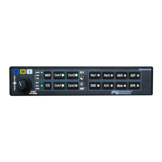
PS Engineering PMA6000B Audio Selector Panel and Intercom System Installation Manual Table of Contents Section I GENERAL INFORMATION..................... 1-1 INTRODUCTION........................1-1 SCOPE ............................. 1-1 EQUIPMENT DESCRIPTION ....................1-1 APPROVAL BASIS - FAA...................... 1-2 SPECIFICATIONS ........................1-2 EQUIPMENT SUPPLIED ....................... 1-3 EQUIPMENT REQUIRED BUT NOT SUPPLIED .............. - Page 3 Figure 1-1 PMA6000B ..........................1-1 Figure 2-1 Screw Locations......................... 2-6 Figure 2-4 Backlight selection jumper location ................... 2-6 Figure 2-3 Adjustments ..........................2-7 Figure 3-1 PMA6000B without Marker (-0100) ..................3-1 Figure 3-2 PMA6000B with Marker (-0300) ....................3-1 Revision History Date...
-
Page 4: Section I General Information
Dual concentric knobs control intercom volume and intercom squelch. A 3-light Marker Beacon receiver is integral to the PMA6000B (without option 2). This provides the neces- sary Marker Beacon light and audio indications necessary for an Instrument Landing System (ILS) ap- proach. -
Page 5: Approval Basis - Faa
PS Engineering PMA6000B Audio Selector Panel and Intercom System Installation Manual APPROVAL BASIS – FAA & EASA TSO/ETSO Approval. The PMA6000-series are FAA approved under TSO C50c (Audio Amplifiers) and TSO C35d (Marker Beacon Receivers). The PMA6000-Series is EASA Approved under ETSO C50c and ETSO 2C35d, ref EASA.IM.210.10028565... -
Page 6: Equipment Supplied
PS Engineering PMA6000B Audio Selector Panel and Intercom System Installation Manual Mic Freq. Response, ±3 dB: 350 Hz - 6000 Hz Music Freq. Response, ±3 dB 200 Hz - 15 kHz Frequency: 75 MHz Crystal Controlled Sensitivity: 450 Volts (Hard) Factory adjusted to 1400V (Soft) 160 Volts (Hard) -
Page 7: Section Ii -Installation
If the PMA6000B is installed in a 27.5 VDC aircraft system, a 15 , 15 Watt dropping resistor (p/n 701- 015-1501) should be installed. Failure to do so will generate unnecessary heat inside the unit and may void PS Engineering's warranty. -
Page 8: Mounting Requirements
2.3.2 Mounting Requirements The PMA6000B must be rigidly mounted to the instrument panel of the aircraft structure and within view and reach of the pilot position(s). Installation must comply with FAA Advisory Circular AC 43.13-2B. The unit may be mounted in any area where adequate clearance for the unit and associated wiring bundle exist. -
Page 9: Entertainment Input
There must be at least 13.8 VDC present at the bottom connector, pin 43, of the PMA6000B for the power supply to work in its designed regulation. Otherwise, it cannot adequately attenuate power line noise. Shielding can reduce or prevent radiated noise (i.e., beacon, electric gyros, switching power supplies, etc.) However, installation combinations can occur where interfer-... -
Page 10: Pma6000B Pin Assignments
Only the person who presses their PTT switch will be heard over the ra- dio. If the pilot and copilot both use the PTT, the copilot position has access to the radio. The pilot position will have PTT control regardless of the copilot when the PMA6000B is in the F mode. -
Page 11: Transmit Interlock
2.4.8.1 Backlighting As shipped from the factory, the PMA6000B is configured for 14V dimmer systems. For 28V dimmer sys- tems remove jumper J9. NOTE: Take precautions to prevent ESD damage prior to servicing unit Remove qty. -
Page 12: Middle Marker Sense
The MM Sense output Pin 27, is connected to certain specific autopilots, and goes high only when a middle marker signal is received, not in test. 2.4.10 Unswitched Inputs The PMA6000B has two unswitched inputs. pin 7 and pin 22 are unswitched/unmated inputs that are heard by the crew and over the cockpit speaker at all times. 200-066-0200 Page 2-6 Rev 6, Feb. -
Page 13: 2.4.11 Intercom
All mic and headphone jacks must have insulating washers, the cable must be Teflon coated, twisted- shielded wire, and the shield must only be connected to the ground return wire only at the intercom con- nector. Note: A custom wiring harness is available from PS Engineering, along with 4-place jack kits. Visit www.ps-engineering.com Adjustments The PMA6000 is factory adjusted to accommodate the typical requirements for most aircraft configurations. -
Page 14: Unit Installation
Split Mode. Unit Installation To install the PMA6000B, gently slide the unit into the mounting rack until the hold-down screw is en- gaged. While applying gentle pressure to the face of the unit, tighten the 3/32" hex-head screw next to the copilot control shaft until the unit is secure. -
Page 15: Marker Checkout
PS Engineering PMA6000B Audio Selector Panel and Intercom System Installation Manual 11. Press and hold the Com 1 Xmt button. While holding the Com 1 button, press the Com 2 Xmt button. This places the unit in “Split Mode;” Verify that the pilot can transmit and receive on Com 1, while the copilot transmits and receives on Com 2. -
Page 16: Section Iii Operation
Panel/Intercom Systems. Please read it carefully before using the equipment so that you can take full ad- vantage of its capabilities. This guide is divided into sections covering the basic operating areas of the PMA6000B systems. They are: Audio Selector, Audio Selection, Intercom, and Marker Beacon Receiver (if equipped). -
Page 17: Volume Control (2)
Only the person who presses their Push-To-Talk (PTT), will be heard over the aircraft radio. The PMA6000B-Series has an automatic selector mode. Audio from the selected transceiver is automatical- ly heard in the headsets and speaker (when selected). You can check this function by switching from C to C 2 and watch the selected audio light on the selector change from Com 1 to Com 2. -
Page 18: Split Mode
3.7.1 Adjusting the VOX-Squelch control (6) The PMA6000B provides a single VOX squelch control for the pilot, copilot and the passengers, although each microphone has it’s own squelch circuit, and only a microphone spoken into will be open. Since the number of microphones open at any one time is reduced, the amount of background noise is diminished. -
Page 19: Soft Mute
They may also listen to Entertainment 1. Passengers can continue to communicate with themselves without interrupting the Crew and also may listen to Entertainment 2. Anytime the PMA6000B is in "Split Mode" the pilot and copilot do not have any intercom function. The passengers will maintain intercommunications. - Page 20 PS Engineering PMA6000B Audio Selector Panel and Intercom System Installation Manual sensitivity to give you a more accurate location of the Outer Marker. The momentary down switch position is labeled "T " and illuminates all three lamps simultaneously to assure the lamps are in working order.
-
Page 21: Section Iv- Warranty And Service
PS Engineering, Inc. warrants this product to be free from defect in material and workmanship for a period of one (1) year from the date of sale. During this one-year warranty period, PS Engineering, Inc., at its op- tion, will send a replacement unit at our expense if the unit should be determined to be defective after con- sultation with a factory technician. -
Page 22: Appendix A External Ptt Hook Up
PTT switch is depressed. A simple modification can be performed to allow proper intercom operation. NOTE: This mod does not alter normal operation. Below are some examples of typical modifications. Contact PS Engineering or the PTT manufacturer for more details if necessary. -
Page 23: Appendix B- Installation Drawing (Not To Scale)
PS Engineering PMA6000B Audio Selector Panel and Intercom System Installation Manual Appendix B- Installation Drawing (not to scale) 431-891-0100 Retaining Block 44-pin connector 475-440-0007 (4 ea) Ø0.20 in 8 plcs Ø0.50 in 2 plcs 475-440-1038 ( 2) Rack back plate... - Page 24 6. 28V installations require 15 ohm, 15W dropping resistor. Not required for 14v aircraft. Nav 2 Audio Hi VHF Nav 2 7. For PMA6000B without marker, marker audio can be Nav 2 Low interfaced through pin 39 (aux), and will ADF Audio Hi ADF Receiver appear when MKR button pushed.
-
Page 25: Appendix F -Instructions For Continuing Airworthiness And Faa Form 337
Powerplant, Propeller, or Appliance) In the case of the PM6000B audio panel you may use the fol- lowing text as a guide. Installed 4-place intercom/audio selector panel, PS Engineering PMA6000B, part number 6000B in center stack instrument panel location designated for panel mounted avionics at station Installed per AC43.13-2B, Chapter 2. - Page 26 PS Engineering PMA6000B Audio Selector Panel and Intercom System Installation Manual Appendix E RTCA DO160B Environmental Qualification Form Audio Selector Panel/Intercom/Marker Beacon Receiver Part Number: 6000 FAA TSO Number: C50c, C35b Class A EASA ETSO C50c, 2C35d EASA.IM.210.10028565 Manufacturer: PS Engineering Incorporated 9800 Martel Road...
Need help?
Do you have a question about the PMA6000B and is the answer not in the manual?
Questions and answers