
Related Manuals for Xtralis XCC-010


Summary of Contents for Xtralis XCC-010
- Page 1 Xtralis Class C (XCC) Product Guide XCC-010 XCC-01000-MRN May 2011 D/N: 14159_07 P/N: 29185...
- Page 3 You acknowledge that you have not relied on any oral or written information, representation or advice given by or on behalf of Xtralis or its representatives.
- Page 4 XCC Product Guide Xtralis Pty Ltd Document Conventions The following typographic conventions are used in this document: Convention Description Bold Used to denote: emphasis Used for names of menus, menu options, toolbar buttons Italics Used to denote: references to other parts of this document or other documents.
- Page 5 This Xtralis product incorporates a laser device and is classified as a Class 1 laser product that complies with FDA regulations 21 CFR 1040.10. The laser is housed in a sealed detector chamber and contains no serviceable parts.
- Page 6 XCC Product Guide Xtralis Pty Ltd This page is intentionally left blank. www.xtralis.com...
-
Page 7: Table Of Contents
Xtralis Pty Ltd XCC Product Guide Table of Contents Introduction Features Pipe Networks XCC-010 with Drilled Holes XCC-010 with Capillaries Wiring Connections Termination Card Relay Terminals Relay settings and conditions to change states Auxiliary / GPI Terminals Programming Socket Typical Wiring to a Fire Panel with an EOL Resistor... - Page 8 XCC Product Guide Xtralis Pty Ltd This page is intentionally left blank. www.xtralis.com...
-
Page 9: Introduction
XCC Product Guide Introduction The Xtralis Class C (XCC) detector is an Air-sampling Smoke Detector designed to protect commercial facilities of up to 800m² to EN 54-20 Class C sensitivity levels. The detector monitors the environment for conditions that indicate the presence or potential of a fire and annunciates via indicators and relay outputs. -
Page 10: Features
The XCC features make it an ideal smoke detection apparatus for protecting a wide range of Class C environments. The features include: The XCC-010 detector can cover an area of up to 800 m² (8000 sq. ft.) Multiple Fire-Alarm threshold settings for specified pipe networks... -
Page 11: Pipe Networks
Xtralis Pty Ltd XCC Product Guide Pipe Networks Note: To achieve EN 54-20 Class C compliance you must use the pre-engineered pipe networks described in this section. These pre-engineered pipe networks provide installations which have a sensitivity better than 8% obscuration/m and transport time better than 90 sec. -
Page 12: Xcc-010 With Drilled Holes
For the given pipe lengths and number of holes, use hole sizes as defined in Table 2-1 or Table 2-2. All holes to be evenly spaced along the pipe (+/- 20%). Table 2-1: Pre-engineered pipe networks for XCC-010 with drilled holes - single pipe Pipe... -
Page 13: Xcc-010 With Capillaries
The internal diameter of the capillary tube must be 8mm. Each capillary must be capped and drilled to the holes sizes specified below. Capillary lengths may be in the range 0.25m to 4m. Table 2-3: Pre-engineered pipe networks for XCC-010 with capillaries - single pipe Pipe Length... - Page 14 XCC Product Guide Xtralis Pty Ltd This page is intentionally left blank. www.xtralis.com...
-
Page 15: Wiring Connections
Xtralis Pty Ltd XCC Product Guide Wiring Connections Termination Card The Termination Card acts as the interface for PC configuration, Power Supply Terminals and Relay Terminals. Terminal A Terminal B FIRE-ALARM Bias (-) (GND) (NO) FIRE-ALARM (C) Reset (-) (GPI) -
Page 16: Auxiliary / Gpi Terminals
The Reset (GPI) terminals are used for either Reset, Mains OK or Standby functions (refer to Table 3-2). Note that Xtralis VSC configuration is required to select the required GPI function. There are two connection methods available for the GPI input: Method 1: Use the Bias terminals which provide 10 VDC supply to initiate the required GPI function (Figure 3-2). -
Page 17: Programming Socket
The 9 pin programming socket on the termination card provides the communication interface between the detector and a PC running Xtralis VSC. Connect the PC to the detector using a RS232 data cable directly to the 9 pin programming socket. -
Page 18: Power Source
XCC Product Guide Xtralis Pty Ltd Power Source The power terminals on the termination card connect to a 24VDC power supply. The four power terminals enable power to be brought into the detector and looped out to another device. The detector has reverse polarity protection to minimize the risk of reverse power connection to the detector. -
Page 19: Installation
Xtralis Pty Ltd XCC Product Guide Installation Mounting the Detector The XCC detector can be mounted onto the wall using the mounting bracket on any suitable secure surface. Note: The detector can only be mounted using the mounting bracket included with the packaging. -
Page 20: Connection To Pipe Network
XCC Product Guide Xtralis Pty Ltd Connection to Pipe Network 4.2.1 Inlet Pipes To connect the detector to the Pipe Network: 1. Ensure a minimum length of 500 mm (20 in.) of straight pipe before terminating the pipe at the air inlet port of the detector. -
Page 21: Battery Backup
Xtralis Pty Ltd XCC Product Guide Battery Backup The power supply for the XCC detector may be switched to a back up battery in the event of the supply being disrupted. The size of the battery back up is determined by local standards and codes, the total power required by the system, back up time required, allowance for reduction in capacity with age and expected temperature variations. -
Page 22: Commissioning
Xtralis Pty Ltd Commissioning Commissioning follows installation and power-up of the detector and involves the following steps: 1. Use Xtralis VSC to: Accept factory default configurations. Check that the fire-alarm threshold setting is appropriate to the pre-engineered design used. Select appropriate air flow threshold setting. -
Page 23: Installation Checklist
Xtralis Pty Ltd XCC Product Guide Installation Checklist Site Name Address Detector Serial Number(s) and Date of Manufacture Name of Installer Signature Date Perform the following checks listed below to ensure that all the necessary items are completed before handing over to a commissioning engineer. - Page 24 XCC Product Guide Xtralis Pty Ltd This page is intentionally left blank. www.xtralis.com...
-
Page 25: Operation
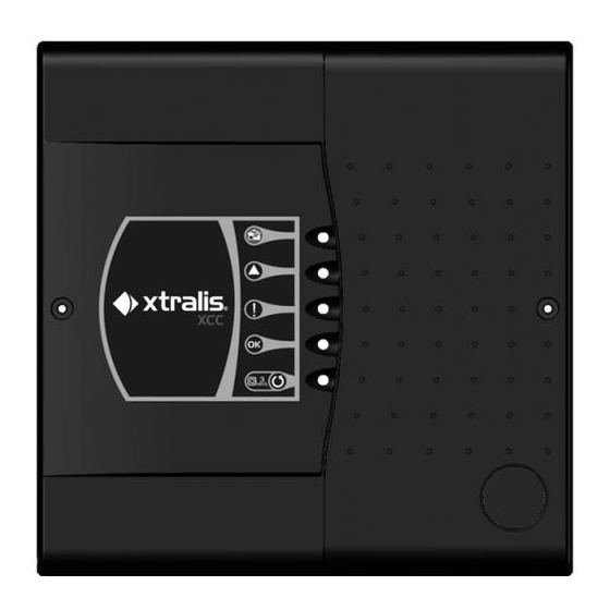
Xtralis Pty Ltd XCC Product Guide Operation Display Fire-Alarm This LED is illuminated when the unit detects a fire. Pre-Alarm This Pre-Alarm LED is illuminated when the unit detects a potential fire event developing. Fault This LED is illuminated when a fault is detected. - Page 26 XCC Product Guide Xtralis Pty Ltd This page is intentionally left blank. www.xtralis.com...
-
Page 27: Maintenance And Servicing
Xtralis Pty Ltd XCC Product Guide Maintenance and Servicing To maintain the XCC detector at its peak performance the maintenance schedule given below should be followed. Maintenance can be conducted by the original installer, a distributor, or a service contractor. -
Page 28: Opening And Closing The Detector
XCC Product Guide Xtralis Pty Ltd Opening and Closing the Detector Figure 6-2: Opening and closing the detector 6.2.1 Opening 1. Undo the two screws on front cover. 2. Open the front cover and allow cover to hang by the attached plastic strap. -
Page 29: Replacing The Filter Cartridge
5. Insert a new air filter cartridge. 6. Tighten the filter screw (B). 7. Connect to a PC with Xtralis VSC software to the programming socket via an RS232 cable. 8. Enter your user level and PIN number to log on to the detector. -
Page 30: Replacing The Aspirator
XCC Product Guide Xtralis Pty Ltd Replacing the Aspirator 1. Remove the 4 screws securing the termination card (A). 2. Disconnect the wires on the aspirator (B). 3. Gently pull out termination card (A) from the interface card (You can't see the interface card, it is con- nected to the back of the termination card). -
Page 31: Product Information
Xtralis Pty Ltd XCC Product Guide Product Information Specifications Table 7-1: XCC detector specifications Model XCC-010 Supply Voltage 18 to 30 VDC Power Consumption 5.4 W quiescent, 5.9 W with alarm Current Consumption 225 mA at 24 VDC normal operation, 245 mA with alarm Fuse Rating 1.6A... -
Page 32: Dimensions
XCC Product Guide Xtralis Pty Ltd Dimensions Figure 7-1: Dimensions of the XCC detector in mm. (in.) www.xtralis.com... - Page 33 Xtralis Pty Ltd XCC Product Guide Figure 7-2: XCC detector dimensions - rear view www.xtralis.com...
-
Page 34: Default Settings
XCC Product Guide Xtralis Pty Ltd Default Settings Table 7-2: Default values for the XCC detector Parameter Default Range Minimum Value Access Minimum Maximum Fire-Alarm Threshold Level I Level I Level IV (highest (lowest sensitivity, sensitivity, lowest highest threshold) threshold) -
Page 35: Index
Xtralis Pty Ltd XCC Product Guide Index EN54-20 iii, 3, 5 Exhaust Pipe end-cap Exhaust Port Filter Cartridge 21, 23, 28 Exhaust 13-14, 17 Hose External Devices inlet port 14, 17, 21 Air Flow 4, 9, 16, 19, 28 FACP... - Page 36 XCC Product Guide Xtralis Pty Ltd RS232 LED Terminals Load Sensitivity 3, 28 Loop Module Serial Number Service 21, 28 Simultaneous Alarm Delays Mains OK Spare Parts Maintenance 3-4, 21 Standby 10, 15, 19 Mounting Startup Mounting Bracket 13, 17...
Need help?
Do you have a question about the XCC-010 and is the answer not in the manual?
Questions and answers