Table of Contents
Advertisement
Integrated Instruction Manual
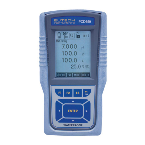
WP 600 Series Meters
pH 600 / 610 / 620, COND 600 / 610, DO 600,
PC 650, PD 650, CD 650, PCD 650
68X415307
Rev. 4 June 2010
Technology Made Easy ...
Part of Thermo Fisher Scientific
99 Washington Street
Melrose, MA 02176
Phone 781-665-1400
Toll Free 1-800-517-8431
Visit us at www.TestEquipmentDepot.com
Advertisement
Table of Contents


Need help?
Do you have a question about the pH 600 and is the answer not in the manual?
Questions and answers