Table of Contents
Advertisement
Quick Links
89 BIF/BAF
Chemical Free Iron Filter
1. Read all instructions carefully before operation.
2. Avoid pinched o-rings during installation by applying (providedwith install kit) NSF certified lubricant to all seals.
3. This system is not intended for treating water that is microbiologically unsafe or of unknown quality without adequate disinfection before or after
the system.
Canada West
655 Park St.
7503 35th St. SE
Regina, SK S4N 5N1
Calgary, AB T2C 1V3
Canada East
U.S.A.
490 Pinebush Rd., Unit 1
193 Osborne Rd.
Cambridge, ON N1T 0A5
Fridley, MN 55432
9760 Mayflower Park Drive,
4655 McDowell Rd. W
Suite 110
Phoenix, AZ 85035
Carmel, IN 46032
Advertisement
Table of Contents

Related Manuals for Hydrotech 89 BIF


Summary of Contents for Hydrotech 89 BIF
- Page 1 89 BIF/BAF Chemical Free Iron Filter 1. Read all instructions carefully before operation. 2. Avoid pinched o-rings during installation by applying (providedwith install kit) NSF certified lubricant to all seals. 3. This system is not intended for treating water that is microbiologically unsafe or of unknown quality without adequate disinfection before or after the system.
-
Page 3: Table Of Contents
READ THIS MANUAL FIRST SPECIFICATION SYSTEM DIMENSIONS HOW DOES THE CHEMICAL FREE BIF/BAF IRON FILTER WORK? CONTAMINANTS FOUND IN WATER UNPACKING INSPECTION BEFORE INSTALLATION INSTALLATION INSTALLATION STEPS PREPARATIONS STARTUP INSTRUCTIONS SYSTEM CHECK LIST DURING REGENERATION PLUMBING SYSTEM CLEAN-UP WATER BYPASS OPERATING CONDITIONS MAINTENANCE INSTRUCTIONS / BACKWASHING INSTRUCTIONS SERVICING 89 VALVE... -
Page 4: Read This Manual First
READ THIS MANUAL FIRST Read this manual thoroughly to become familiar with the device and its capabilities before installing or operating your Water Filter. Failure to follow instructions in this manual could result in personal injury or property damage. This manual will also help you to get the most out of your filter. This system and its installation must comply with state and local regulations. -
Page 5: Specification
SPECIFICATION BIF-100 BIF-150 BIF-200 BIF-300 BIF-400 Specifications BAF-100 BAF-150 BAF-200 BAF-300 BAF-400 Specifications Typical Service Flow Rate 3.0 gpm 4.0 gpm 5.0 gpm 6.0 gpm 7.0 gpm BIFMN-100 BIFMN-150 BIFMN-200 BIFMN-300 BIFMN-400 Peak Flow Rate 6.0 gpm 10.0 gpm 12.0 gpm 14.0 gpm 16.0 gpm Typical Service Flow Rate 3.0 gpm... -
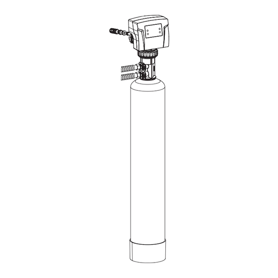
Page 6: System Dimensions
SYSTEM DIMENSIONS Models A (Inches) B (Inches) C (Inches) BXX-75 57.5" 13" 20" BXX-100 62.5" 15" 21" BXX-150 67.5" 16" 22" BXX-200 65.5" 17" 24" BXX-300 77.5" 18" 26" BXX-400 77.5" 19" 28" HOW DOES THE CHEMICAL FREE BIF IRON FILTER WORK? This filter works by adding oxygen to the incoming water by passing it through a bubble of compressed air. - Page 7 Carbon Filter (BIFC Models) Cont... common treatment method in terms of volume of water treated annually because it’s inexpensive, easy to maintain and doesn’t produce potentially harmful reaction products such as tri-halo-methanes (THMs). Another method is the use of catalytic carbon to sulfide reduction through oxidation of sulfides with dissolved oxygen present in the water. Reduction of sulfides with catalytic activated carbon first involves adsorption of the sulfide species and then catalytic oxidation.
-
Page 8: Contaminants Found In Water
CONTAMINANTS FOUND IN WATER IRON (Fe) Iron concentrations as low as 0.3 ppm will cause staining. The iron concentration, together with the flow rate demand and the consumption rate of the water determines the basic size filter system. The higher these factors are, the larger the required system. The filter system is capable of filtering out the three main types of iron found in water supplies: Soluble iron (also known as “clear water”... -
Page 9: Unpacking
UNPACKING / INSPECTION Be sure to check the entire unit for any shipping damage or parts loss. Also note damage to the shipping cartons. Contact the transportation company for all damage and loss claims. The manufacturer is not responsible for damages in transit. Small parts, needed to install the filter, are in a parts box. - Page 10 For Models BXX20, BXX30 and BXX40, the media and Control Valve is packaged separately in carton and bags What is included with BXX, 20, 30 and 40 models? There are 7 Red clips. 1. Tank 1 c/w Parallel Adaptor Please check to make 2.
- Page 11 Check Valve Type and Valve Serial # Check to make sure Valve Type if Downflow (DF) (left Sticker shown below). The right Sticker shows the serial # of the control valve. The middle Sticker is dataplate which provides information of Serial # and Date of Manufacture of complete system. Both Serial # labels are important for troubleshooting. Complete System Serial # Item # Desc...
-
Page 12: Before Installation
BEFORE INSTALLATION Contact your local distributor to use Canature WaterGroup™ laboratory for complete water analysis free of cost and no obligation to you. The laboratory addresses can be found on the front page of the manual. All government codes and regulations governing the installation of these devices must be observed. - Page 13 NOTE: If your pumping rate is inadequate, do not install your filter until the problem is solved. Tools Required for Installation: Two adjustable wrenches Additional tools may be required if modification to home plumbing is required. Plastic inlet and outlet fittings are included with the filter. To maintain full valve flow, 3/4” or 1” pipes to and from the filter fittings are recommended. You should maintain the same, or larger, pipe size as the water supply pipe, up to the filter inlet and outlet.
-
Page 14: Installation
INSTALLATION Proper installation sequence of water conditioning equipment is very important. Refer to the diagrams following for your particular water supply. NOTE: The Braukman air vent is not approved for use in the State of Wisconsin. An approved air to water tank and/or air vent should be used with this application in the State of Wisconsin. -
Page 15: Installation Steps
Installation of the Flow Control Switch (Mascontrol) as Power Source 1. Used when pressure switch and air pump are in alternate locations. Also used on constant pressure or variable speed pump systems. 2. Mascontrol acts as a flow control detecting flow. 3. -
Page 16: Preparations
PREPARATIONS Media Installation (When Necessary). Models including and higher than (BXX20, BXX30, BXX40) of media are shipped with separate media in pails or boxes. Models lower than 1.5 CF of media come loaded with media and this step can be skipped for new installation. CAUTION! The unit should be de-pressurized before installing or replacing media Plug Riser... - Page 17 NOTE: Some medias like those used in BIF/BIFMN Models are sacrificial and deplete faster depending on inlet water conditions and usage. The media replenishment is more frequent in high water usage and more acidic water cases. The dome hole models are avail- able and supplied in which the dome hole is available for a quick addition or replenish- ment of media in the tank...
- Page 18 3. Outside faucets used to water lawns and gardens should not supply untreated water. A new water line is often required to be connected to supply untreated water to the inlet of the water filter and to the outside faucets. Cut the water line between where it enters the house and before any lines that branch off to feed the hot water heater or other fixtures in the house and as near the desired location of the water filter as possible.
- Page 19 6. Connect Filter to the house plumbing. Any solder joints near the valve must be done before connecting any piping to the valve. Always leave at least 6” (152 mm) between the valve and joints when soldering pipes that are connected to the valve. Failure to do this could cause damage to the valve. Correct Installation of the Check Valve: Install 1”...
-
Page 20: Startup Instructions
STARTUP INSTRUCTIONS Familiarize with Button Configuration: 1. Connect the transformer to the valve. Plug the 12-volt transformer into a 120 VAC 60 Hz outlet. Date and Time 18-Apr-2016 10:35AM MENU Days to Regen 3 The controller will show the following on the screen - Time, Date and number of Days Remaining for Regeneration Key Pad Configuration:... - Page 21 4a. (CARBON UNITS – Model BIFCXX) Open the inlet on the bypass valve slightly and very slowly allow water to enter the unit. (If the water enters too quickly it will push the media or carbon up into the control valve and get plugged). Once the unit has filled sufficiently that water is at least equal to the height of the top of the media shut down the water for 15 –...
-
Page 22: System Check List
SYSTEM CHECK LIST More than 90% of problems affecting the efficiency of a chemical iron free filter system can be identified in 9 minutes or less by following this diagnostic schedule. Start with Step 1, then follow each step in sequence to ensure proper diagnostic procedures. 1. -
Page 23: Water Bypass
3. Close main water supply valve or turn power off to pump and proceed with filter installation. During time required to install filter system, iron- fouled softener resin will be chemically cleaned. 3. After filter installation is completed and final adjustments are made with the water turned on and brine draw tube reconnected, manually reposition timer on softener to backwash position. -
Page 24: Maintenance Instructions / Backwashing Instructions
MAINTENANCE INSTRUCTIONS Your chem free iron filter requires some minor maintenance to ensure optimum performance and years of trouble-free clean water. The following steps should be performed once or twice a year (more often under harsh conditions): 1. Verify the pumping rate of the system - do not refer to a pumping curve for this data. Follow the instructions found on page 7. If the measured pumping rate is less than the backwash rate of the filter, see page 39, Trouble Shooting. -
Page 25: Servicing 89 Valve
PEOPLE IRON CONTENT (PPM) 1. Locate the box intersected by the number of people in your family and FAMILY the parts per million (ppm) of iron in your water (if your ppm is between two numbers on the guide, use the higher number). 2. -
Page 26: Timer Replacement
TIMER REPLACEMENT 4 X Screws Meter Cable Front Cover 1. Disconnect the meter cable? from the meter. (If flow 2. Remove four screws from the back of the valve cover 3. Remove the front cover of the valve. meter is attached) Piston Screw Washer 2 X Screws from Powerhead... -
Page 27: Meter Assembly Replacement
METER ASSEMBLY REPLACEMENT (For Models Manufactured after Valve Serial # Date of November 2015) Meter Cable 2X Clips 1. Disconnect the meter cable from the meter. 4. Remove the meter support and then the impeller out from the coupling and 2. -
Page 28: Meter Assembly Replacement (For Models Manufactured Before Valve Serial # Date Of November 2015)
METER ASSEMBLY REPLACEMENT (For Models Manufactured before Valve Serial # Date of November 2015) Remove Meter Cable screws Meter Support 2X Clips Special Tool Impeller 1. Disconnect the meter cable from the meter. 4. Remove six screws and pull out the meter support and impeller. 2. -
Page 29: Circuit Board Replacement
CIRCUIT BOARD REPLACEMENT Circuit Board Screws Wire connections to Circuit Board 1. Remove the screws from the back of the valve and pull the front 2. Remove all connections from the circuit board cover 3. Remove the fours screws from the circuit board and pull it out SERVICING OF PARALLEL ADAPTOR Tank and Valve Connection Parts A. -
Page 30: Parts Breakdown
PARTS BREAKDOWN Part # Part # Screen Part # 60010244 60010009 60020267 Part # 121780 (1” Brass or Control Valve Part # Stainless Steel Check Valve 60010067 Part # 80070013 (1” PVC Part # Check Valve Check Valve) 60010012 (3/8SCV) Tank 2 Tank 1 Part # 60010021... - Page 31 PARTS BREAKDOWN Controller assembly parts list Part # Part Description 60010570 Controller front cover assembly 92388 89 PCB 60010571 PCB absorb shock foam 60010572 PCB fix screws 60010573 85HE mounting plate 60010574 Screws 92389 85 drive gear 60010099 Connect screw 92391 85HE main gear 60010575...
- Page 32 PARTS BREAKDOWN Parts list of Standard connection assembly Part # Part Qty No. Part # Part Description Description 60010258 Big O-ring of 92387 89 secure clip Adaptor coupling 60010585 Adaptor coupling of 89 60010589 89 valve control valve connector 60010586 Small O-ring of 60010590 Connector O-ring...
- Page 33 PARTS BREAKDOWN Parts list of control valve body: Part # Part Description 89 valve body 60010227 95 secure clip See next DLFC assembly: optional section 1S, 2S, 3S, 4S, 1#, 3#, 4#, 5#, 6# 60010211 Drain elbow O-ring 92397 Drain elbow: 1/2” 60010233 3/4”...
- Page 34 PARTS BREAKDOWN DLFC PART # for 89 VALVE BLFC PART # for 89 VALVE Part # Part Description Part # Part Description 60095720 BNT95DLFC-0(4.0 GPM) 60010128 BNT95BLFC (0.2 GPM) 60010143 BNT95DLFC-1(7.0GPM) 12053 BNT95BLFC-1(2.0 GPM) 60010144 BNT95DLFC-2(11.0GPM) 60010162 BNT95 BLFC-7(1.35 GPM) 60010145 BNT95DLFC-3(14.0GPM) 60010146...
-
Page 35: Trouble Shooting Guide (89Bif/Baf)
TROUBLE SHOOTING GUIDE (89 BIF/BAF) 1. Water is clear when drawn, turns red upon standing (stain producing) a) Insufficient air drawn by the valve- Check Air Draw time b) Bypass open or leaking - Close bypass valve and/or repair as necessary... - Page 36 MASTER PROGRAMMING GUIDE (89BIF/BAF) The controller will show the following on the screen - Time, Date and number of Days Remaining for Regeneration: = Initial Setup Interface = = Initial Setup Interface = = Initial Setup Interface = = Initial Setup Interface = Language Language Language...
- Page 37 MASTER PROGRAMMING GUIDE (89BIF/BAF) PRESS “MENU” KEY AND SCROLL TO “MAIN MENU”. THEN PRESS “SET” TILL IT BEEPS. SCROLL TO ADVANCED MENU Press “Menu” key . Press - to advance to Advanced Menu Press and hold “SET” 5 seconds or until you hear a beep. Press “+” or “-”...
-
Page 38: Diagnostic Screen
DIAGNOSTIC SCREEN PRESS “MENU” KEY AND SCROLL TO “MAIN MENU”. THEN PRESS “SET” TILL IT BEEPS. SCROLL TO ADVANCED MENU Press - to advance to History Values Press “Menu” key . Press - to advance to Main Menu Press“SET” or until you hear a beep. Press “SET”... -
Page 39: How To Set Date And Time, Manual Regeneration And Dealer Information
HOW TO SET DATE AND TIME, MANUAL REGENERATION AND DEALER INFORMATION PRESS “MENU” KEY AND SCROLL TO “MAIN MENU”. THEN PRESS “SET” TILL IT BEEPS. Press “Menu” key Press “+” or “-” to change menu option. Press “SET” to enter. Press “+”... -
Page 40: Warranty
Canature WaterGroup™ guarantees that your new water conditioner is built of quality material and workmanship. When properly installed and maintained, it will give years of trouble free service. Seven Year Warranty on 89 Control Valve Canature WaterGroup™ will repair or replace the failed control valve with reburbished valve for 7 years provided the failure is due to a defect in material or workmanship and not the result of damage from any conditions described in the general conditions of this warranty.
Need help?
Do you have a question about the 89 BIF and is the answer not in the manual?
Questions and answers