Yaesu FT-65R Operating Manual
144/430 mhz dual band transceiver
Hide thumbs
Also See for FT-65R:
- Quick start manual ,
- Advance manual (39 pages) ,
- Instruction manual (22 pages)
Table of Contents
Advertisement
Quick Links
Advertisement
Table of Contents

Related Manuals for Yaesu FT-65R


Summary of Contents for Yaesu FT-65R
- Page 1 144/430 MHz DUAL BAND TRANSCEIVER FT-65 FT-65 Operating Manual...
-
Page 2: Table Of Contents
Contents General Description ..........1 Automatic Repeater Shift (ARS) ....26 Features of the FT-65R/E ........ 1 Manual Repeater Shift Setting ...... 27 About this manual ..........2 Tone Calling (1750 Hz) ........28 Downloading the “Advance Manual” ....3 Memory Mode ............ -
Page 3: General Description
General Description Features of the FT-65R/E FT-65R/E is a dual band FM transceiver, ruggedly constructed to meet com- mercial specifications. It is packed with the following popular and valuable features demanded by Amateur Radio operators around the world. Long-Life Battery Supplied 7.4 V 1,950 mAh lithium ion battery. -
Page 4: About This Manual
This icon indicates other pages containing relevant informa- tion. This icon refers users to the FT-65R/E Advance Manual on the YAESU Website containing relevant information. • The settings of the transceiver at the time of purchase are referred to as the “default”... -
Page 5: Downloading The "Advance Manual
Downloading the “Advance Manual” The Advance Manual provides detail information and features beyond the scope and descriptions in this manual. Download the FT-65R/E Advance Manual from the YAESU website and refer to it along with this Operating Manual. http://www.yaesu.com/ The features described in the FT-65R/E Advance Manual are below. -
Page 6: Accessories & Options
This product is designed to perform optimally when used with genuine Yaesu accessories. Yaesu shall not be liable for any damage to this product and/or accidents such as fire, leakage or explosion of a battery pack, etc., caused by the malfunction of non-Yaesu accessories. -
Page 7: Safety Precautions
Yaesu is not liable for failures and other problems caused due to misuse or use of this product by you or a third party. Also, Yaesu is not liable for damages caused through use of this product by you or a third party except in the case where ordered to pay for damages under the laws. - Page 8 In such a diately turn off this product and case, consult the doctor immedi- disconnect the external anten- ately. na from it. A fire, electrical shock, or damage may result. FT-65R/FT-65E Operating Manual...
- Page 9 Do not use any battery charger Do not disassemble or make which is not specified by Yaesu. any alteration A fire or failure can result. to this product. An injury, electric shock, or failure When transmitting, keep the can result.
- Page 10 FT- 65R/E may fall or drop, result- used for an extended period, ing in an injury or damage. turn it off and remove the bat- tery pack for safety. Do not drop, strike, or throw the transceiver. A failure or damage may result. FT-65R/FT-65E Operating Manual...
- Page 11 TV, or the Noise generated by an onboard radio. electrical device (inverter, etc.) can disrupt the normal operation of the transceiver. Do not use any products other than the specified options and accessories. A failure can result. FT-65R/FT-65E Operating Manual...
-
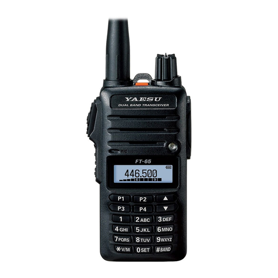
Page 12: Control & Connections (Top & Front Panel)
† Microphone ................The internal microphone is located here. ‡ LED Flash-Light ˆ LCD (Liquid Crystal Display) ..........The display shows current operating condition. ‰ Keypad .................. These 18 keys select the important operating functions of the FT-65R/E. FT-65R/FT-65E Operating Manual... -
Page 13: Controls & Connections (Side Panel)
Press and hold this key to enter the Set Mode. „ SP Jack This three-conductor miniature jack provides connection for an external speaker. … MIC Jack This three-conductor miniature jack provides connections for microphone audio, earphone audio, PTT, and ground. FT-65R/FT-65E Operating Manual... -
Page 14: Controls & Connections (Lcd)
21 3 Battery Indicator ....2 Operating Frequency ..20 4 VFO-A / VFO-B ………… The Set Mode and Preference Mode display Set Mode Preferred Operating Mode Preferred Operating Mode Menu .. 5 Set Mode Menu ....22 6 ..........FT-65R/FT-65E Operating Manual... -
Page 15: Display Of Features And Settings
40 25 ..........15 Keypad Lock ....24 26 Selecting ICON indicator Memory (BANK) Channel Num- 16 VOX Feature ....42 27 Automatic Power-Off Feature ..........* This feature is displayed depending on the transceiver version. FT-65R/FT-65E Operating Manual... -
Page 16: Controls & Connections (Keypad)
*1 : When entering a frequency from the keypad, there is a short-cut for frequencies ending in zero - after the last non-zero digit, press and hold the [0/SET] key to enter all the zeros at once. FT-65R/FT-65E Operating Manual... -
Page 17: Installation Of Accessories
1. Insert the battery pack into the bat- tery compartment on the back of the transceiver( ). 2. Push the battery in until the battery latch on the lower back side of the transceiver clicks securely( ‚ ). FT-65R/FT-65E Operating Manual... -
Page 18: Removing The Battery Pack
Attaching the Belt Clip Attach the belt clip on the back of transceiver using the supplied screws (two). FT-65R/FT-65E Operating Manual... -
Page 19: Charging The Battery Pack
Charging the Battery Pack If the battery has never been used, or its charge is depleted, it may be charged by placing the FT-65R/E in the SBH-22 Rapid Charger desktop cra- dle, connected with the SAD-20B/C/U/G AC adapter. AC line outlet... -
Page 20: Low Battery Indication
144 MHz band Approx. 10.0 hours Approx. 12.5 hours Amateur Band 430 MHz band Approx. 9.0 hours Approx. 11.5 hours FM Broadcast Band Approx. 11.0 hours Approx. 15.0 hours Transmit 6 seconds; Receive 6 seconds; Stand by 48 seconds. FT-65R/FT-65E Operating Manual... -
Page 21: Basic Operation
Frequency ranges are shown in the table. Frequency Range USA model 136-174 MHz 144-148 MHz 400-480 MHz 430-450 MHz European 136-174 MHz 144-146 MHz 400-480 MHz 430-440 MHz model Asian model 136-174 MHz 136-174 MHz 400-480 MHz 400-480 MHz FT-65R/FT-65E Operating Manual... -
Page 22: Frequency Navigation
Basic Operation Frequency Navigation The FT-65R/E will initially be operating in the “VFO” mode. The VFO permits free tuning throughout the currently-selected operating band in designated frequency steps (operating channels). Three basic frequency navigation methods are provided on the FT-65R/E. -
Page 23: Transmission
Basic Operation The direction of the scan may not reverse while FT-65R/E is scanning. For more details on the scanning, see page 35. Transmission • To transmit, press the PTT switch, and speak into the front panel micro- phone (located in the lower left-hand corner of the speaker grille) in a nor- mal voice level. -
Page 24: Activating The Set Mode
3. Press and hold the [P1], [P2], [P3] or [P4] key to assign the Set Mode Item to the Quick Recall Key. 4. Press the [P1], [P2], [P3] or [P4] key to recall the assigned Set Mode Item. FT-65R/FT-65E Operating Manual... -
Page 25: Settings To A Quick Recall Key (Quick Memory Feature)
3. When the LCD backlight comes on, release the MONI/T.CALL key and PTT switch. 4. Referring to the above table, press the [▲] or [▼] key to select the desired operating mode. 5. Press the F key momentarily to activate the selected operating mode. FT-65R/FT-65E Operating Manual... -
Page 26: Advanced Operation
Advanced Operation After becoming familiar with the basic operations of the FT-65R/E, you will want to learn about some of the really handy operating and convenience fea- tures. Turning the Keylock Feature ON and OFF The FT-65R/E keypad may be locked to prevent accidental frequency change or inadvertent transmissions, 1. -
Page 27: Disabling The Keypad And Scan Stop Beeper
6. Press the PTT switch to save the new setting and return to normal oper- ation. 7. To turn the beep back on again, select “KEY” or “KEY+SC (Default setting)” in step 4 above. FT-65R/FT-65E Operating Manual... -
Page 28: Repeater Operation
Repeater stations are often located on mountaintops or other high locations, and provide a dramatic extension of the communication range for low-pow- ered hand-held or mobile transceivers. The FT-65R/E includes a number of features which make repeater operation simple and enjoyable. -
Page 29: Manual Repeater Shift Setting
6. Press the F key to enable adjustment of this Item. 7. Press the [▲] or [▼] key to select the repeater shift magnitude (0.05 MHz ~ 99.95 MHz). 8. Press the PTT switch to save the new setting and return to normal oper- ation. FT-65R/FT-65E Operating Manual... -
Page 30: Tone Calling (1750 Hz)
T.CALL key for the time duration specified by the repeater owner/operator. The transmitter will automatically be activated, and the 1750-Hz audio tone will be superimposed on the carrier. Once the repeater is accessed, release the MONI/T.CALL key and use the PTT switch to activate the transmitter thereafter. FT-65R/FT-65E Operating Manual... -
Page 31: Memory Mode
Memory Mode The FT-65R/E provides a wide variety of memory system resources. These include: • 200 “Standard” memory channels, numbered “001” through “200”. • 3 “Home” channels, providing storage and quick recall of one prime fre- quency on each operating band. -
Page 32: Memory Storage
5. Press and hold the [ V/M] key to store the frequency and settings into the selected memory channel. “MEM-IN” on the display will blink twice and the tone will sound to com- plete the memory setting. FT-65R/FT-65E Operating Manual... -
Page 33: Memory Recall
• To correct a mistake, press the [▼] key repeatedly until the cursor returns to the character position. For more details on character/symbol input, see page 38. 6. Press the PTT switch to save the new setting and return to the memory channel. FT-65R/FT-65E Operating Manual... -
Page 34: Home Channel Memory Recall
“VFO” mode. 1. Recall the memory channel. 2. Press the [#BAND] key to activate the “Mem- ory Channel Tuning” feature. The Memory Channel number on the LCD display will be replaced by “tun”. FT-65R/FT-65E Operating Manual... -
Page 35: Deleting Memories
4. Press the [▲] or [▼] key to select the memo- ry channel to be “deleted”. 5. Press the F key to delete the selected mem- ory channel. 6. Press the PTT switch to return to normal operation. FT-65R/FT-65E Operating Manual... -
Page 36: Weather Broadcast Channels
In the event of extreme weather disturbances, such as severe thunderstorms and hurricanes, the NOAA (National Oceanic and Atmospheric Administra- tion) sends a weather alert accompanied by a 1050 Hz tone and subsequent weather report on one of the NOAA weather channels. FT-65R/FT-65E Operating Manual... -
Page 37: Scanning
Scanning The FT-65R/E makes available scanning of the stored memory channels, or scanning of the entire operating band, or scanning of a programmable sub band portion. Scanning will halt when signals are encountered, and commu- nication may be initiated on that frequency. -
Page 38: Vfo Scanning
Scanning VFO Scanning The FT-65R/E provides two VFO scanning functions: “Manual VFO Scan- ning” and “Programmed Mode (VFO) Scanning.” Manual VFO Scan 1. If necessary, press the [ V/M] key to change to the VFO mode. 2. Press and hold the [▲] or [▼] key to initiate upward or downward scanning, respectively. - Page 39 “Pause” condition. 6. The scanner will then resume according to the Scan-Resume mode select- ed in the “RESUME” setting. 7. To cancel scanning, press the PTT switch, [▲] or [▼ ] key. FT-65R/FT-65E Operating Manual...
-
Page 40: Input Character/Symbol List
9 W X Y Z w x y z 4 G H I g h i 0 (blank character) Û + - , . / : ; @ (blank character) 5 J K L j k l 6 M N O m n o FT-65R/FT-65E Operating Manual... -
Page 41: Set (Menu) Mode
Set (Menu) Mode The FT-65R/E Set Mode, already partially described in the previous chap- ters, may be activated to select or change various transceiver functions. Many of the useful parameter configurations have not been fully detailed in this manual. Refer to the chart below for a list of the Set Mode Items and their various parameters. - Page 42 19 MON/T-CL Selects the MONI MONITOR / T-CALL1750 MONITOR (*) or (MON/T-CALL) or T.CALL switch / T-CALL2100 / T-CALL1750 (*) function. T-CALL1000 / T-CALL1450 20 NAME TAG Renames Alpha- Numeric “Tags” for the − − Memory channels. FT-65R/FT-65E Operating Manual...
- Page 43 20 / 25 / 50 / 100 kHz, or AUTO 31 TOT Setting of the TOT 1 min - 30 min (per 1 3min time. min) or OFF 32 TX PWR Selects TX Power HI(5W) / MID(2.5W) / HI(5W) LOW(0.5W) FT-65R/FT-65E Operating Manual...
- Page 44 Narrow (±2.5 kHz) TX Deviation. 38 WX ALERT Enables/Disables the ALT.OFF / ALT. ON ALT.OFF Weather Alert Scan feature. Inversion scrambling SCRB.OFF/SCRB.ON SCRB.OFF SCRAMBLE(*) (Encryption) ) : This function may be displayed, depending on the transceiver ver- sion. FT-65R/FT-65E Operating Manual...
-
Page 45: Troubleshooting
Check the remaining charge on the battery pack. In addition, using an inadequate power supply where voltage drops during transmission will prevent the FT-65R/E from operating at full capability. The keys or DIAL do not respond. • Is the Keypad Lock or PTT Lock on? -
Page 46: The Battery Pack Cannot Be Charged Or Battery Power Depletes Immediately After Charging
The battery pack cannot be charged or battery power depletes immediately after charging. • Is the battery pack being charged with a charger specified by Yaesu? Charge the battery pack using the accessory battery charger (SAD-20B/ C/U/G) or the rapid charge cradle (SBH-22). -
Page 47: Specifications
(@ 7.4 V with SBR-25LI) Modulation Type: Variable Reactance F2D, F3E Maximum Deviation: ±5.0 kHz (F2D, F3E) Spurious Emission: At least 60 dB down (@ High and Middle power) At least 40 dB down (@ Low power) Microphone Impedance: 2 kOhms FT-65R/FT-65E Operating Manual... -
Page 48: Receiver
Asian/European Version Frequency Range Frequency Range Mode Step Mode Step (MHz) (MHz) 136.000-160.600 12.5 kHz 400.000-430.000 12.5 kHz 160.600-162.025 25 kHz 430.000-440.000 25 kHz 162.025-174.000 12.5 kHz 440.000-470.000 12.5 kHz 470.000-480.000 50k Hz 65.000-108.000(RX 100 kHz only) FT-65R/FT-65E Operating Manual... - Page 49 Note FT-65R/FT-65E Operating Manual...
- Page 50 1. Changes or modifications to this device that are not expressly approved by YAESU MUSEN could void the user’s authorization to operate this device. 2. This device complies with part 15 of the FCC Rules. Operation is subject to the following two conditions: (1) This device may...
-
Page 51: Declaration Of Conformity
Declaration of Conformity We, Yaesu UK Ltd. certify and declare under our sole responsibility that the following equipment complies with the essential requirements of the Directive 1999/5/EC and 2011/65/EU. Type of Equipment: Dual Band Transceiver Brand Name: YAESU Model Number:... - Page 52 Copyright 2016 YAESU MUSEN CO., LTD. All rights reserved. No portion of this manual may be reproduced without the permission of YAESU MUSEN CO., LTD. YAESU MUSEN CO., LTD. Tennozu Parkside Building 2-5-8 Higashi-Shinagawa, Shinagawa-ku, Tokyo 140-0002 Japan YAESU USA Printed in China 6125 Phyllis Drive, Cypress, CA 90630, U.S.A.
Need help?
Do you have a question about the FT-65R and is the answer not in the manual?
Questions and answers