Table of Contents
Advertisement
Application for FCC / IC
FCC ID: K6620665X20 / IC: 511B-20665X20
VHF/UHF
DUAL BAND TRANSCEIVER
FT-65R/E
O
M
perating
anual
YAESU MUSEN CO., LTD.
Tennozu Parkside Building
2-5-8 Higashi-Shinagawa, Shinagawa-ku, Tokyo 140-0002 Japan
YAESU USA
6125 Phyllis Drive, Cypress, CA 90630, U.S.A.
YAESU UK
Unit 12, Sun Valley Business Park, Winnall Close
Winchester, Hampshire, SO23 0LB, U.K.
Advertisement
Table of Contents

Subscribe to Our Youtube Channel
Related Manuals for Yaesu FT-65R/E


Summary of Contents for Yaesu FT-65R/E
- Page 1 FCC ID: K6620665X20 / IC: 511B-20665X20 VHF/UHF DUAL BAND TRANSCEIVER FT-65R/E perating anual YAESU MUSEN CO., LTD. Tennozu Parkside Building 2-5-8 Higashi-Shinagawa, Shinagawa-ku, Tokyo 140-0002 Japan YAESU USA 6125 Phyllis Drive, Cypress, CA 90630, U.S.A. YAESU UK Unit 12, Sun Valley Business Park, Winnall Close...
-
Page 2: Table Of Contents
Application for FCC / IC FCC ID: K6620665X20 / IC: 511B-20665X20 Ontents Accessories & Options ............................. 1 Supplied Accessories ............................. 1 Available Options ............................1 Control & Connections (Top & Front Panel) ....................2 Control & Connections (Side Panel) ......................3 Installation of Accessories .......................... -
Page 3: Accessories & Options
This product is designed to perform optimally when used with genuine Yaesu accessories. Yaesu shall not be liable for any damage to this product and/or accidents such as fire, leakage or explosion of a battery pack, etc., caused by the malfunction of non-Yaesu accessories. -
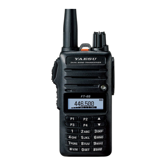
Page 4: Control & Connections (Top & Front Panel)
The internal microphone is located here. LED Flash-Light LCD (Liquid Crystal Display) The display shows current operating condition. Keypad These 18 keys select many of most important operating features on the FT- 65R/E. FT-65R/E Operating Manual... -
Page 5: Control & Connections (Side Panel)
MIC Jack … This three-conduc- t o r m i n i a t u r e j a c k provides connection points for microphone audio, earphone au- dio, PTT, and ground. FT-65R/E Operating Manual... -
Page 6: Installation Of Accessories
To remove the battery, turn the radio off and remove any protective cases. Open the Battery Pack Latch on the bottom of the radio, then slide the battery downward and out from the radio while tilting the Belt Clip out of the way. FT-65R/E Operating Manual... -
Page 7: Battery Charging
If the battery has never been used, or its charge is depleted, it may be charged by connecting the SAD-20 AC adapter to the SBH-22 desktop charger, and place the FT-65R/E in the desktop charger cradle. AC line outlet FT-65R/E / SBH-22 with SAD-20 A fully-discharged pack will be charged completely in 10 hours. -
Page 8: Operation
(or scanning) per the discussion in the next chapter. Frequency Range USA model 136-174 MHz 144-148 MHz 400-480 MHz 430-450 MHz EU model 136-174 MHz 144-146 MHz 400-480 MHz 430-440 MHz EXP model 136-174 MHz 136-174 MHz 400-480 MHz 400-470 MHz FT-65R/E Operating Manual... -
Page 9: Frequency Navigation
If you wish to reverse the direction of the scan (i.e. toward a lower frequency, instead of a higher frequency), just push the [ ] key while the FT-65R/E is scanning. The scanning direction will be reversed. To revert to scanning toward a higher frequency once more, push the [ ... -
Page 10: Transmission
Once you have set up an appropriate frequency inside one of the 144 MHz or 430 MHz Amateur bands on which the FT-65R/E can transmit, you’re ready to go on the air! These are the most basic steps; more advanced aspects of transmitter operation will be discussed later. -
Page 11: Advanced Operation
OCking In order to prevent accidental frequency change or inadvertent transmission, various aspects of the FT-65R/E’s keypad may be locked out. The possible lock- out combinations are: Operation Display Just the front panel keypad is locked out... -
Page 12: Repeater Operation
Repeater stations, usually located on mountaintops or other high locations, pro- vide a dramatic extension of the communication range for low-powered hand- held or mobile transceivers. The FT-65R/E includes a number of features which make repeater operation simple and enjoyable. - Page 13 8. Press the [] or [] key to set the SHIFT frequency, then press the F/W key. 7. When you have made your selection, press the F/W key, then press the PTT switch to save the new setting and return to normal operation. FT-65R/E Operating Manual...
-
Page 14: Ctcss/Dcs Operation
This tone system, called “CTCSS” (Continuous Tone Coded Squelch Sys- tem), is included in your FT-65R/E, and is very easy to activate. 1. Press the F/W key, then press the [ 1 ] or [ 0] key to enable selection of the CTCSS/DCS mode. -
Page 15: Dcs Operation
Another form of tone access control is Digital Code Squelch, or DCS. It is a newer, more advanced tone system which generally provides more immunity from false paging than does CTCSS. The DCS Encoder/Decoder is built into your FT-65R/E, and operation is very similar to that just described for CTCSS. Your repeater system may be configured for DCS; if not, DCS is frequently quite useful in Simplex operation if your friend(s) use transceivers equipped with this advanced feature. -
Page 16: Memory Mode
Application for FCC / IC FCC ID: K6620665X20 / IC: 511B-20665X20 eMOry The FT-65R/E provides a wide variety of memory system resources. These in- clude: 200 “Standard” memory channels, numbered “001” through “200.” 2 “Home” channels, providing storage and quick recall of one prime frequen- cy on each operating band. -
Page 17: Memory Storage
You may also recall the Memory Channel #000 and Programmable Memory channels (“L1/U1” through “L10/U10.”) using the following numbers: Memory Channel #000 = “200,” Programmable Memory channels #L1 = “201,” U1 = “202,” L50 = “209,” and U50 = “210.” FT-65R/E Operating Manual... -
Page 18: Home Channel Memory Recall
165.525 MHz 162.475 MHz 161.650 MHz When the SCAN pauses on a station, 162.425 MHz 161.775 MHz press the PTT Switch once to stop the 162.450 MHz 163.275 MHz scan, or press it again to restart the scan. FT-65R/E Operating Manual... -
Page 19: Fm Broadcast Receiving
1. Press F/W key and then press [0 SET] key to enter the Set mode. 2. Press [▲] or [▼] key to select the “37: WFM RCV”, then press F/W key 3. Set the WFM mode ON/OFF by pressing the [▲] or [▼] key. WFM ON Enable FM Broadcast Radio to input on VFO-B WFM OFF Not Receiving the FM Broadcast Radio and inputting WFM in VFO-B. FT-65R/E Operating Manual... -
Page 20: Scanning
FCC ID: K6620665X20 / IC: 511B-20665X20 Canning The FT-65R/E allows you to scan just the memory channels, the entire operat- ing band, or a portion of that band. It will halt on signals encountered, so you can talk to the station(s) on that frequency, if you like. -
Page 21: Memory Scanning
Broadcast station will seriously impede scanner operation if you are using the “Carrier Drop” Scan-Resume mode, as the incoming signal will not pause long enough for the transceiver to resume scanning. Such channels may be “Skipped” during scanning, if you like: FT-65R/E Operating Manual... -
Page 22: Preferential Memory Scan
MR mode, whether or not it is locked out of the scanning loop). Preferential Memory Scan The FT-65R/E also allows you to set up a “Preferential Scan List” of channels which you can “flag” within the memory system. These channels are designated by a blinking “” icon when you have selected them, one by one, for the Prefer- ential Scan List. -
Page 23: Weather Alert Scan
NOAA Alert Tone while operating using VFO scan or Memo- ry channel scan. When the Weather Alert Scan feature is engaged, the FT-65R/E will check the Weather Broadcast Memory Channels for activity every five seconds while scan- ning. If you watch the display carefully, you’ll observe the scanner periodically... - Page 24 3. Press the F/W key momentarily to enable adjustment of this Set Mode Item. 4. Press [▲] [▼] key to select the “ALT.ON”. 5. When you have made your selection, press the [PTT] switch to save the set- ting and exit to normal operation. 6. To disable the Weather Alert Scan feature, select “ALT.OFF” in step 4 above. FT-65R/E Operating Manual...
-
Page 25: Miscellaneous Settings
5/6.25/10/12.5/15/20/25/50/100 kHz per step, as well as an automatic step selection based on the current operating frequency (“AUTO”), any number of which may be important to your operating requirements. The FT-65R/E is set up at the factory in the “AUTO” configuration, which probably is satisfactory for most operation. -
Page 26: Reset Procedures
F6 VHF-ONLY Operation on the VHF Band only. F7 UHF-ONLY Operation on the UHF Band only. F8 FM-ONLY Operation on the FM-RADIO only. F9 CLONE Clone mode. 4. Press the F/W key momentarily to complete the reset procedure. FT-65R/E Operating Manual... -
Page 27: Set (Menu) Mode
Application for FCC / IC FCC ID: K6620665X20 / IC: 511B-20665X20 The FT-65R/E Set Mode, already described in parts of many previous chapters, is easy to activate and set. It may be used for configuration of a wide variety of transceiver parameters, some of which have not been detailed previously. Use the following procedure to activate the Set Mode: 1. - Page 28 Broadband FM Radio(WFM) WFM.ON / WFM.OFF / WFM.OLY WFM.ON function Enables/Disables WIDE/NAR Select Wide (±5 kHz) or Narrow WIDE / NARROW WIDE (±2.5 kHz) TX Deviation. WX ALERT Enables/Disables the Weather ALT.OFF / ALT. ON ALT.OFF Alert Scan feature. FT-65R/E Operating Manual...
-
Page 29: Specifications
400 mW @ 8 W for 10 % THD (@ 7.5 V) Specifications are subject to change without notice, and are guaranteed within the 144 and 430 MHz amateur bands only. Frequency ranges will vary according to transceiver version; check with your dealer. FT-65R/E Operating Manual... - Page 30 The Scanner receiver is not a digital scanner and is incapable of being converted or modified to a digital scanner receiver by any user. WARNING: MODIFICATION OF THIS DEVICE TO RECEIVE CELLULAR RADIOTELEPHONE SERVICE SIGNALS IS PROHIBITED UNDER FCC RULES AND FEDERAL LAW. FT-65R/E Operating Manual...
- Page 31 Application for FCC / IC FCC ID: K6620665X20 / IC: 511B-20665X20 Copyright 2016 1609x-XX YAESU MUSEN CO., LTD. All rights reserved. Printed in Japan No portion of this manual may be reproduced without the permission of YAESU MUSEN CO., LTD.
Need help?
Do you have a question about the FT-65R/E and is the answer not in the manual?
Questions and answers