
Related Manuals for Bender cme420


Summary of Contents for Bender cme420
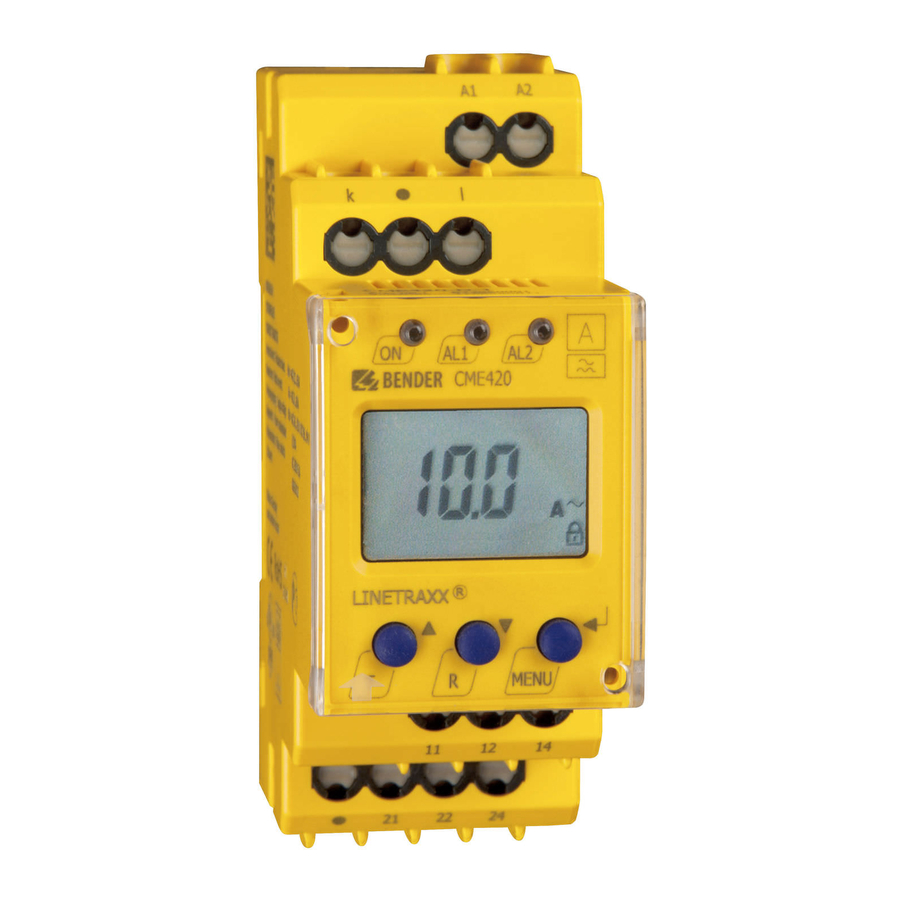
- Page 1 Manual CME420 Multi-functional current relay, AC, overcurrent/undercurrent/ window discriminator function CME420_D00034_00_M_XXEN/07.2013...
- Page 2 Bender GmbH & Co. KG Londorfer Str. 65 • 35305 Gruenberg • Germany Postfach 1161 • 35301 Gruenberg • Germany Tel.: +49 6401 807-0 Fax: +49 6401 807-259 E-Mail: info@bender-de.com Web: http://www.bender-de.com © Bender GmbH & Co. KG All rights reserved.
-
Page 3: Table Of Contents
Table of Contents 1. How to use this documentation effectively ..........5 How to use this manual ................. 5 Symbols ....................... 5 Intended use ...................... 6 Information about factory setting ............. 6 2. Safety information ................... 7 Safety instructions ................... 7 Work activities on electrical installations .......... - Page 4 Table of Contents Menu structure ....................17 Display in standard mode ................. 18 Display in menu mode ................19 5.5.1 Parameter query and setting: overview ..........19 5.5.2 Switching over from overcurrent to undercurrent operation or to window operation ..................21 5.5.3 Response value setting for overcurrent: ..........
-
Page 5: How To Use This Documentation Effectively
1.1 How to use this manual This manual is intended for experts in electrical engineering and elec- tronics! This manual describes the multi-functional current relay CME420. It must be kept ready for referencing in the immediate vicinity of the device. 1.2 Symbols... -
Page 6: Intended Use
How to use this documentation effectively 1.3 Intended use The current monitor is designed to monitor the threshold values of AC cur- rents for overcurrent and undercurrent conditions. In case of direct measure- ment, currents up to 16 A (screw-type terminals) resp. 12 A (push-wire terminals) can be continuously monitored. -
Page 7: Safety Information
2. Safety information 2.1 Safety instructions In addition to this data sheet, the documentation of the device includes a sheet entitled "Important safety instructions for BENDER products“. 2.2 Work activities on electrical installations. Danger of electric shock! Touching live parts will cause danger of electric shock with fatal consequences. - Page 8 Safety information CME420_D00034_00_M_XXEN/07.2013...
-
Page 9: Function
3. Function 3.1 Device features Undercurrent or overcurrent monitoring in AC systems, < I or > I and current monitoring with window discriminator function Indirect current monitoring by means of a current transformer, suitable for transformation ratio factor 1…2000 Adjustable switching hysteresis ... -
Page 10: Automatic Self Test
Function the adjusted delay on release (response value plus hysteresis) after the alarm relays have switched, the delay on release starts "t ". After the expiry of "t “ the alarm relays switch back to their initial position. With activated fault mem- ory, the alarm relays do not change their actual state until the reset button R is pressed. -
Page 11: Specify The Number Of Reload Cycles
Function If the fault continues to exist, please contact the Bender Service. 3.2.4 Specify the number of reload cycles If faults occur only temporarily, but recurrently, in the system being moni- tored, with deactivated fault memory M, the alarm relays would switch syn- chronously to the error status. -
Page 12: Time Delays T, Ton And Toff
Function 3.2.8 Time delays , The times t, t and t described below delay the output of alarms via LEDs and relays. Starting delay After connection to the supply voltage U , the alarm indication is delayed by the preset time t (0…300 s). Response delay on1/2 If the current value exceeds or falls below the threshold value, the current... -
Page 13: Installation And Connection
4. Installation and connection Ensure safe isolation from supply in the installation area. Observe the installation rules for live working! Dimension diagram and drawing for screw fixing The front plate cover is easy to open at the lower part identified by an arrow. CME420_D00034_00_M_XXEN/07.2013... - Page 14 Installation and connection 1. DIN rail mounting: Snap the rear mounting clip of the device into place in such a way that a safe and tight fit is ensured. Screw fixing: Use a tool to move the rear mounting clips (a second mounting clip required, see ordering information) to a position that it projects over the enclosure.
-
Page 15: Operation And Setting
5. Operation and setting 5.1 Used display elements A detailed description of the meaning of the display elements is given in the table below. Elemen Used display elements Function Reload function with memory = off (L = I.) Transformation ratio factor for external current transformer <I Undercurrent... -
Page 16: Function Of The Operating Elements
Operation and setting 5.2 Function of the operating elements Elemen Device front Function Power On LED, green AL1, LED Alarm 1 lights (yellow): Response value 1 reached LED Alarm 2 lights (yellow): Response value 2 reached 1,6 A, I = 1.6 A flow via the terminals k and l, Fault memory active Test button (>... -
Page 17: Menu Structure
Operation and setting 5.3 Menu structure All adjustable parameters are listed in the columns menu item and adjustable parameters. A display-like representation is used to illustrate the parameters in the column menu item. Different alarm categories can be assigned to the alarm relays K1, K2 via the submenus r1, r2. -
Page 18: Display In Standard Mode
Operation and setting Menu Menu Activation Adjustable parameter menu item Setting ranges: I 12 High, window function, Transformation ratio factor external current transformer (device con- trol) Parameter setting via password Re-establish factory settings Function blocked Display hard / software version History memory for the first alarm value, erasa- Display in standard mode... -
Page 19: Display In Menu Mode
Operation and setting 5.5 Display in menu mode 5.5.1 Parameter query and setting: overview Menu Adjustable parameter item Response values query and setting: – Alarm I2 (AL2), (undercurrent, overcurrent or window function can be set in the SEt/I menu) – Prewarning I1 (AL1), (50 % of I2) –... - Page 20 Operation and setting Menu structure CME420_D00034_00_M_XXEN/07.2013...
-
Page 21: Switching Over From Overcurrent To Undercurrent Operation Or To Window Operation
Operation and setting Parameter settings An example is given below on how to change the alarm response value for overcurrent > I1. It is presumed that the option overcurrent (HI) has been se- lected in the SEt/I menu (factory setting). Proceed as follows: 1. -
Page 22: Response Value Setting For Overcurrent
Operation and setting 5.5.3 Response value setting for overcurrent: - Response value I2 (overcurrent) - Response value I1 (overcurrent) - Hysteresis (Hys) of the response values I1, I2 Increasing the response value I2 (Example: overcurrent) Increasing the response value I1 (prewarning overcurrent Setting the hysteresis of the response value CME420_D00034_00_M_XXEN/07.2013... -
Page 23: Setting The Fault Memory And Operating Principle Of The Alarm
Operation and setting 5.5.4 Setting the fault memory and operating principle of the alarm relays Deactivating the fault memory Setting the alarm relay K1 to N/O operation (n.o.) Setting the number of reload cycles CME420_D00034_00_M_XXEN/07.2013... -
Page 24: Assigning Alarm Categories To The Alarm Relays
Operation and setting 5.5.5 Assigning alarm categories to the alarm relays Overcurrent, undercurrent and device-related errors of the current monitor can be assigned to the alarm relays K1 (r1, 1) and K2 (r2, 2). By default, the alarm relays K1 and K2 signal prewarning and alarm in case of overcurrent. Alarm relay K1: Deactivating the category device error Alarm relay K1: Deactivating the category response value I1 CME420_D00034_00_M_XXEN/07.2013... - Page 25 Operation and setting Alarm relay K1: Activating the category response value I2 Alarm relay K1: Deactivating the category device test When an alarm relay (K1/K2) has been deactivated in the menu, an alarm will not be signalled by the respective changeover contact! An alarm will only be indicated by the respective alarm LED (AL1/AL2)! CME420_D00034_00_M_XXEN/07.2013...
-
Page 26: Setting The Time Delays
Operation and setting 5.5.6 Setting the time delays The following delays can be specified: Response delay t (0…300 s) for K1, and t (0…300 s) for K2 Starting delay t (0…10 s) when the device is being started ... -
Page 27: Changing From Overcurrent Operation To Window Operation
Operation and setting Setting the starting delay 5.5.7 Changing from overcurrent operation to window operation Use this menu item to set whether the response values of the device apply to overcurrent (HI) or undercurrent operation (Lo). In addition, window opera- tion (In) can be selected. -
Page 28: Setting The Transformation Ratio For External Current Transformer
Operation and setting 5.5.8 Setting the transformation ratio for external current trans- former Factory setting and password protection Use this menu to activate the password protection, to change the password or to deactivate the password protection. In addition, you can reset the device to its factory settings. - Page 29 Operation and setting b) Changing the password c) Deactivating the password protection CME420_D00034_00_M_XXEN/07.2013...
-
Page 30: Re-Establishing The Factory Settings
Operation and setting 5.5.9 Re-establishing the factory settings Device information query This function is used to query the hardware (d…) and software (1.xx) versions. After activating this function, data will be displayed as a scrolling text. Once one pass is completed you can select individual data sections using the Up/ Down keys. -
Page 31: Commissioning
Operation and setting 5.6 Commissioning Prior to commissioning, check proper connection of the current relay. Danger of fire! Please note the maximum permissible measuring current continuously applied is in case of direct measurement: Push-wire terminals: 12 A Screw-type terminals: 16 A Factory setting Response value overcurrent I1 (prewarning) 5 A (50 % of I2) -
Page 32: Timing Diagram: Current Monitoring
Operation and setting 5.8 Timing diagram: Current monitoring t = Starting delay, t = Response time, t = Delay on release CME420_D00034_00_M_XXEN/07.2013... -
Page 33: Technical Data
Maximum nominal voltage of the system being monitored when the conductor being monitored is directly connected: With protective separation..........................AC 230 V Without protective separation ......................... AC 400 V Supply voltage CME420-D-1: Supply voltage ......................AC 16…72 V / DC 9.6…94 V Frequency range ........................... 42…460 Hz... - Page 34 Technical data Response values Undercurrent Undercurrent< I (alarm ), direct connection: Push-wire terminal........................AC 0.1…12 A (1 A)* Screw-type terminal........................AC 0.1…16 A (1 A)* or external current transformer Undercurrent < I (prewarning ) ..................100 %…200 % (150 %)* Overcurrent Overcurrent >...
- Page 35 Technical data Password ............................Off / 0…999 (Off)* Fault memory (M) alarm relay ......................... on / off (on)* Switching elements Number ..................2 relays, with one changeover contact each (K1, K2) Operating principle............N/C operation n.c. / N/O operation n.o. (N/C operation n.c.)* Electrical service life under rated operating conditions............
-
Page 36: Ordering Information
( )* = factory setting 6.2 Ordering information Supply voltage U Device type Response value Art. No. DC 9.6 V…94 V / CME420-D-1 0.1…12 A x n B 7306 0001 AC 42…460 Hz, 16…72 V (push-wire terminal) DC 9.6 V…94 V / CME420-D-1 0.1…16 A x n... - Page 37 INDEX LED Alarm 2 lights 16 Adjustable parameters, list 17 Automatic self test 10 Malfunction 10 Manual self test 10 Manual, target group 5 Deleting the fault alarms 16 Menu Device features 9 - AL (response values) 17 Display in standard mode 18 - HiS (history memory for the first alarm value) 18 Enter key 16...
- Page 38 - Changing from overcurrent opera- tion to window operation 27 - Deactivating the fault memory 23 - Response value setting 22 - Setting the time delay 26 Password protection 12 Release delay toff 12 Reset button 16 Response delay ton 12 Response value setting - Hysteresis 22 - Overcurrent (>...
- Page 40 D0003400MXXEN Bender GmbH & Co. KG Londorfer Str. 65 • 35305 Gruenberg • Germany Postfach 1161 • 35301 Gruenberg • Germany Tel.: +49 6401 807-0 Fax: +49 6401 807-259 E-Mail: info@bender-de.com Web: http://www.bender-de.com...
Need help?
Do you have a question about the cme420 and is the answer not in the manual?
Questions and answers