National Instruments NI 9512 Operating Instructions Manual
Stepper drive interface module with encoder feedback
Hide thumbs
Also See for NI 9512:
- Operating instructions and specifications (45 pages) ,
- User manual (72 pages) ,
- Getting started (36 pages)
Table of Contents
Advertisement
Quick Links
Download this manual
See also:
User Manual
Advertisement
Table of Contents

Related Manuals for National Instruments NI 9512


Summary of Contents for National Instruments NI 9512
- Page 1 OPERATING INSTRUCTIONS AND SPECIFICATIONS NI 9512 Stepper Drive Interface Module with Encoder Feedback Français Deutsch ni.com/manuals...
-
Page 2: Safety Guidelines
Refer to the documentation for each component in the system to determine the safety ratings and specifications for the entire system. Safety Guidelines Operate the NI 9512 only as described in these operating instructions. This icon denotes that the component may be Hot Surface hot. -
Page 3: Special Conditions For Marine Applications
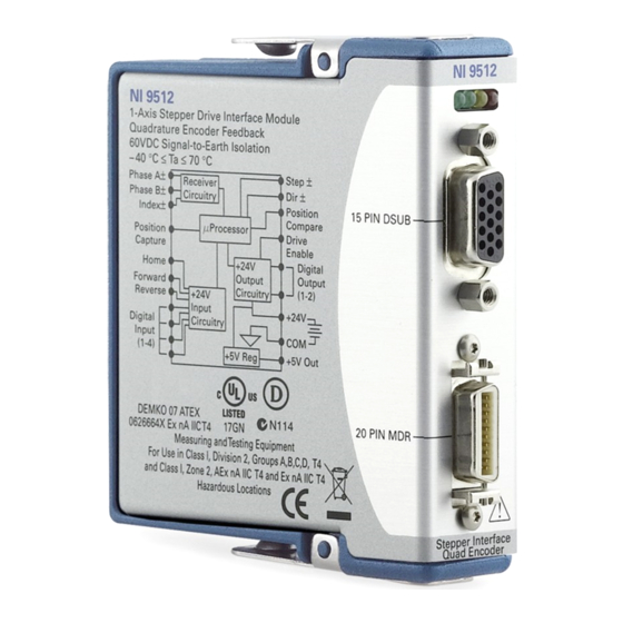
Connecting the NI 9512 The NI 9512 stepper drive interface module is part of a family of C Series motion modules. The module provides stepper drive interface signals for a single axis, a full set of motion I/O including... -
Page 4: System Connection
Working together they produce smoother motion resulting in precise stepper motion control. System Connection The NI 9512 has two connectors, a 15-pin DSUB drive interface connector and a 20-pin MDR feedback connector. The 15-pin DSUB includes command signals for interfacing with stepper drives, 0 to 30 V general-purpose digital input and output lines, and a +19 to 30 V input for power connection. - Page 5 National Instruments offers several options for connecting the NI 9512 to stepper drives. You can use the NI 9512-to-P7000 Stepper Drives Connectivity Bundle to connect the NI 9512 to the P70530 or P70360 stepper drives from NI. To connect to third-party stepper drives, you can use the NI 951x Cable and Terminal Block Bundle.
- Page 6 NI 9512-to-P7000 Stepper Drives Connectivity Bundle, the NI 951x Cable and Terminal Block Bundle, or a custom cable for direct connectivity. 3. Connect the NI 9512 module to an external power supply. Do not connect anything to pins marked Caution Reserved.
- Page 7 NI 9512 Limit and Home NI Connection Sensors Accessory/ Custom Cable Power Supply Step±/CW Direction±/CCW Drive Drive Fault Drive Enable Motor Stepper Motor Encoder (Optional) Figure 1. NI 9512 Connection Example © National Instruments Corp. NI 9512 Operating Instructions and Specifications...
- Page 8 Table 1. NI 9512 DSUB Connector Pin Assignments Connector Signal Reserved Drive Enable Digital Input 3 Digital Input 2 Digital Output 1 Reserved Digital Input 1 Direction (CCW)– Step (CW)– Digital Output 0 Direction (CCW)+ Step (CW)+ ni.com NI 9512 Operating Instructions and Specifications...
- Page 9 Encoder 0 Phase A– Encoder 0 Index– Encoder 0 Phase B+ Position Capture +5 V OUT Encoder 0 Phase B– Position Compare Figure 2. NI 9512 MDR Connector Pin Assignments © National Instruments Corp. NI 9512 Operating Instructions and Specifications...
- Page 10 Digital Input 3 Direction (CCW)+ † Direction (CCW)– † † Digital Input 2 † Step (CW)+ † Step (CW)– Shield † Indicates DSUB connector signals. Figure 3. NI 9512 37-Pin Terminal Block Pin Assignments ni.com NI 9512 Operating Instructions and Specifications...
-
Page 11: Signal Connections
Signal Connections Figure 4 shows the NI 9512 block diagram. Phase A± (0) Buffer Step ± Receiver Phase B± (0) Circuitry Index± (0) Buffer Direction ± Position Buffer Capture Position Buffer Home Compare Microprocessor Drive Forward Enable Reverse Digital Output... - Page 12 , for more information about signal connections. manuals The NI 9512 module supports both industry standards for stepper command signals—step and direction, or clockwise (CW) and counterclockwise (CCW) pulse outputs. The step and direction output circuits are software configurable for either single-ended or differential output type.
- Page 13 NI 9512 Step+ output to the negative (cathode) side of the optocoupler input, and leave the Step– output on the NI 9512 disconnected. Connect the positive (anode) side of the drive input to a supply as specified by the drive manufacturer.
- Page 14 Encoder NI 9512 Phase + +5 V Receiver Phase – Figure 7. Differential Encoder Input Circuit Encoder NI 9512 +5 V Phase+ +5 V Receiver Phase– Connection Figure 8. Single-Ended Encoder Input Circuit ni.com NI 9512 Operating Instructions and Specifications...
- Page 15 PNP (Sourcing) Output Device NI 9512 Limit, Home, or Digital Input Limit, Home, or Digital Input Configured For Sinking V– (Reference) Figure 9. Limit or Digital Input Circuit Configured for Sinking © National Instruments Corp. NI 9512 Operating Instructions and Specifications...
- Page 16 (Reference) Figure 10. Limit or Digital Input Circuit Configured for Sourcing The NI 9512 Drive Enable and Digital Output <1..2> circuits are software configurable for sinking or sourcing output type and the active state is software configurable for on or off.
- Page 17 NI 9512 Drive Enable or Drive Enable or Digital Output Digital Output Configured Sinking For Sourcing Circuit V– (Reference) Figure 11. Drive Enable or Digital Output Circuit Configured for Sourcing © National Instruments Corp. NI 9512 Operating Instructions and Specifications...
- Page 18 NI 9512 Input Device NI 9512 Sourcing Circuit Drive Enable or Digital Output Drive Enable or Digital Output Configured For Sinking V– (Reference) Figure 12. Drive Enable or Digital Output Circuit Configured for Sinking ni.com NI 9512 Operating Instructions and Specifications...
-
Page 19: Led Indicators
LED Indicators The NI 9512 has four LEDs to display status information. 1 Axis Status (Green) 3 Limit Active (Yellow) 2 Encoder Active (Green) 4 Axis Fault (Red) Axis Status The Axis Status LED (green) has three states to display axis status. -
Page 20: Encoder Active
) is connected and the module is receiving encoder pulses. The LED flash rate does not correspond to the rate Note at which the NI 9512 receives encoder pulses. • Lit—The power supply (V ) is connected but the module is not receiving encoder pulses. -
Page 21: Sleep Mode
In sleep mode, the system consumes minimal power and may dissipate less heat than it does in normal mode. Refer to the Specifications section for more information about power consumption and thermal dissipation. © National Instruments Corp. NI 9512 Operating Instructions and Specifications... -
Page 22: Specifications
Sourcing 20 mA ....3.5 V min Sourcing 12 mA ....3.7 V min Sourcing 4 mA ..... 3.9 V min Low, V Sinking 20 mA ..... 0.9 V max Sinking 12 mA ..... 0.7 V max ni.com NI 9512 Operating Instructions and Specifications... - Page 23 Drive enable output Output type......... Programmable: sinking or sourcing Voltage range......0 to 30 V input........19 to 30 V Continuous output current (I on each channel ......±100 mA max © National Instruments Corp. NI 9512 Operating Instructions and Specifications...
- Page 24 Input high range ....300 mV to 5 V Input low range ....–300 mV to –5 V Common-mode voltage ..–7 to 12 V Common-mode voltage is the average of Phase+ and Phase–. ni.com NI 9512 Operating Instructions and Specifications...
- Page 25 Input current......≥2 Input impedance ......30 kΩ ±5% Assumes the minimum filter setting. Refer to the NI SoftMotion Module book of the LabVIEW Help for more information about filter options. © National Instruments Corp. NI 9512 Operating Instructions and Specifications...
- Page 26 Sourcing 12 mA ....3.7 V min Sourcing 4 mA ..... 3.9 V min Assumes the minimum filter setting. Refer to the NI SoftMotion Module book of the LabVIEW Help for more information about filter options. ni.com NI 9512 Operating Instructions and Specifications...
- Page 27 Pulse width (programmable) Min........100 ns Max ........1.6 ms Active state ......... Programmable: high or low Digital I/O Inputs Number of inputs......4 Input type........Programmable: sinking or sourcing © National Instruments Corp. NI 9512 Operating Instructions and Specifications...
- Page 28 ......±100 mA max ) ....0.3 Ω max Output impedance (R Assumes the minimum filter setting. Refer to the NI SoftMotion Module book of the LabVIEW Help for more information about filter options. ni.com NI 9512 Operating Instructions and Specifications...
-
Page 29: Power Requirements
Active mode ....... 1.5 W max Sleep mode ......... 0.4 mW max input .......... 19 to 30 V, 375 mA max +5 V regulated output ....... 5 V ±5%, 150 mA max © National Instruments Corp. NI 9512 Operating Instructions and Specifications... -
Page 30: Physical Characteristics
Weight..........155 g (5.5 oz) Safety Safety Voltages Connect only voltages that are within the following limits. Channel-to-COM ......0 to +30 VDC max, Measurement Category I ni.com NI 9512 Operating Instructions and Specifications... - Page 31 Such voltage measurements include signal levels, special equipment, limited-energy parts of equipment, circuits powered by regulated low-voltage sources, and electronics. Do not connect the NI 9512 to signals or use for Caution measurements within Measurement Categories II, III, or IV.
-
Page 32: Electromagnetic Compatibility
• EN 55011 (CISPR 11): Group 1, Class A emissions • AS/NZS CISPR 11: Group 1, Class A emissions • FCC 47 CFR Part 15B: Class A emissions • ICES-001: Class A emissions ni.com NI 9512 Operating Instructions and Specifications... -
Page 33: Online Product Certification
To obtain product certifications and the DoC for this product, visit ni.com/ , search by module number or product line, certification and click the appropriate link in the Certification column. © National Instruments Corp. NI 9512 Operating Instructions and Specifications... -
Page 34: Shock And Vibration
18 shocks at 6 orientations Environmental National Instruments C Series modules are intended for indoor use only, but may be used outdoors if installed in a suitable enclosure. Refer to the manual for the chassis you are using for more information about meeting these specifications. -
Page 35: Environmental Management
Max altitude ........2,000 m Pollution Degree ....... 2 Environmental Management National Instruments is committed to designing and manufacturing products in an environmentally responsible manner. NI recognizes that eliminating certain hazardous substances from our products is beneficial to the environment and to NI customers. - Page 36 WEEE recycling center. For more information about WEEE recycling centers and National Instruments WEEE initiatives, visit ni.com/ environment/weee.htm National Instruments (RoHS) National Instruments RoHS (For information ni.com/environment/rohs_china about China RoHS compliance, go to ni.com/ environment/rohs_china ni.com NI 9512 Operating Instructions and Specifications...
-
Page 37: Where To Go For Support
Where to Go for Support The National Instruments Web site is your complete resource for technical support. At you have access to ni.com/support everything from troubleshooting and application development self-help resources to email and phone assistance from NI Application Engineers. - Page 38 South Africa 27 0 11 805 8197, Spain 34 91 640 0085, Sweden 46 (0) 8 587 895 00, Switzerland 41 56 2005151, Taiwan 886 02 2377 2222, Thailand 662 278 6777, Turkey 90 212 279 3031, United Kingdom 44 (0) 1635 523545 ni.com NI 9512 Operating Instructions and Specifications...
- Page 39 National Instruments, NI, ni.com, and LabVIEW are trademarks of National Instruments Corporation. Refer to the Terms of Use section on ni.com/legal for more information about National Instruments trademarks. Other product and company names mentioned herein are trademarks or trade names of their respective companies.
Need help?
Do you have a question about the NI 9512 and is the answer not in the manual?
Questions and answers