National Instruments NI 9514 Operating Instructions And Specifications
Servo drive interface module with feedback
Hide thumbs
Also See for NI 9514:
- User manual (72 pages) ,
- Getting started (35 pages) ,
- Operating instructions and specifications (42 pages)
Table of Contents
Advertisement
Quick Links
Advertisement
Table of Contents

Related Manuals for National Instruments NI 9514


Summary of Contents for National Instruments NI 9514
- Page 1 NI-9514...
- Page 2 OPERATING INSTRUCTIONS AND SPECIFICATIONS NI 9514 Servo Drive Interface Module withFeedback Français Deutsch ni.com/manuals...
-
Page 3: Related Information
This document describes how to use the National Instruments 9514 module and includes specifications and pin assignments for the NI 9514. The safety guidelines and specifications in this Note document are specific to the NI 9514. The other components in the system may not meet the same safety ratings and specifications. -
Page 4: Safety Guidelines For Hazardous Locations
Safety Guidelines for Hazardous Locations The NI 9514 is suitable for use in Class I, Division 2, Groups A, B, C, D, T4 hazardous locations; Class I, Zone 2, AEx nA IIC T4 and Ex nA IIC T4 hazardous locations; and nonhazardous locations only. -
Page 5: Special Conditions For Hazardous Locations Use In Europe And Internationally
II 3G and is suitable for use in Zone 2 hazardous locations, in ambient temperatures of –40 °C Ta 70 °C. If you are using the NI 9514 in Gas Group IIC hazardous locations, you must use the device in an NI chassis that has been evaluated as Ex nC IIC T4, Ex IIC T4, Ex nA IIC T4, or Ex nL IIC T4 equipment. -
Page 6: Electromagnetic Compatibility Guidelines
To minimize the potential for the product to cause interference to radio and television reception or to experience unacceptable performance NI 9514 Operating Instructions and Specifications | © National Instruments | 5... -
Page 7: Special Guidelines For Marine Applications
Furthermore, any changes or modifications to the product not expressly approved by National Instruments could void your authority to operate it under your local regulatory rules. To ensure compliance with the applicable... - Page 8 Connecting the NI 9514 The NI 9514 servo drive interface module is part of a family of C Series motion modules. The module provides servo drive interface signals for a single axis, a full set of motion I/O including inputs for a home switch and limit switches, incremental encoder inputs for position feedback, and 0 to 30 V digital input lines.
-
Page 9: System Connection
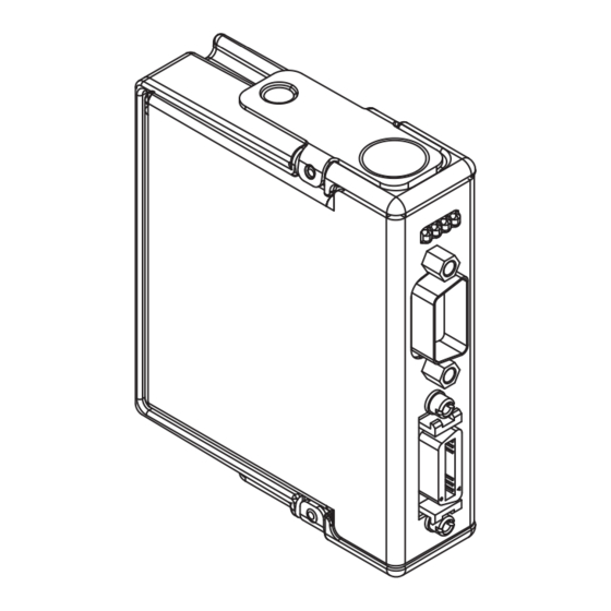
System Connection The NI 9514 has two connectors, a 15-pin DSUB drive interface connector and a 20-pin MDR feedback connector. The 15-pin DSUB includes command signals for interfacing with servo amplifiers or drives, a 0 to 30 V general-purpose digital input line, and a 19 to 30 V input for power connection. - Page 10 NI 9514 Connection Options National Instruments offers several options for connecting the NI 9514 to servo drives. You can use the NI 9514/16 to AKD cable to connect the NI 9514 to the AKD analog servo drive and AKM series servo motors from NI. To connect to third-party servo drives use the NI 951x Cable and Terminal Block Bundle.
- Page 11 LabVIEW Help for information about chassis, slot, or software restrictions. 2. Connect the module to a drive and other I/O using the NI 9514/16 to AKD cable, the NI 951x Cable and Terminal Block Bundle, or a custom cable for direct connectivity to third-party drives.
- Page 12 Forward, Reverse Limit, Home Drive Fault Vsup NI 9514 Limit and Home NI Connection Sensors Accessory/ Custom Cable Power Supply Drive Command Drive Enable Drive Drive Fault Motor Servo Motor Encoder NI 9514 Operating Instructions and Specifications | © National Instruments | 11...
- Page 13 Table 1. NI 9514 DSUB Connector Pin Assignments Connector Signal Drive Command Drive Enable Reserved Reserved Reserved Drive Command Digital Input 1 Reserved Reserved Reserved Vsup Reserved 12 | ni.com | NI 9514Operating Instructions and Specifications...
- Page 14 Encoder 0 Phase B+ Encoder 0 Phase A– Encoder 0 Index– Encoder 0 Phase A+ Encoder 0 Index+ Reserved Digital Input 0 Reserved Home Reverse Limit Forward Limit NI 9514 Operating Instructions and Specifications | © National Instruments | 13...
- Page 15 Figure 3. NI 9514 37-Pin Terminal Block Pin Assignments Reserved Forward Limit Home Reverse Limit Reserved Digital Input 0 Reserved Encoder 0 Index+ Encoder 0 Phase A+ Encoder 0 Index– Encoder 0 Phase A– Encoder 0 Phase B+ +5V OUT...
-
Page 16: Signal Connections
Input Reverse Circuitry Digital Input (0-1) +5V Reg +5V OUT This document provides a brief overview of the Note module signal connections. Refer to the NI 951x User NI 9514 Operating Instructions and Specifications | © National Instruments | 15... -
Page 17: Drive Command Output
, for more information about signal connections. Drive Command Output The NI 9514 module provides a ±10 V analog Drive Command output. Use the Drive Command COM signal instead of COM as a reference for the Drive Command Output. This reference signal helps keep digital noise separate from the analog output. -
Page 18: Limit And Digital Input Signals
You can configure the Forward Limit, Reverse Limit, and Digital Input <1..2> signals in software for sinking or sourcing output devices and set the active state of the inputs in software to NI 9514 Operating Instructions and Specifications | © National Instruments | 17... - Page 19 Figure 7 shows an example of wiring the input signals to a sourcing output device. Figure 7. Limit or Digital Input Circuit Configured for Sinking PNP (Sourcing) Output Device NI 9514 Limit, Home, or Digital Input Limit, Home, Current...
-
Page 20: Drive Enable
Do not connect the Drive Enable output to a Caution +5 V input circuit when the Drive Enable output is configured for sourcing. NI 9514 Operating Instructions and Specifications | © National Instruments | 19... - Page 21 Figure 9 shows an example of wiring the output signals to a sinking input device. Figure 9. Drive Enable Output Circuit Configured for Sourcing NPN (Sinking) NI 9514 Input Device NI 9514 Vsup Drive Enable Drive Enable Configured Sinking For Sourcing Circuit V–...
- Page 22 Figure 10. Drive Enable Output Circuit Configured for Sinking PNP (Sourcing) NI 9514 Input Device NI 9514 Vsup Sourcing Circuit Drive Enable Drive Enable Configured For Sinking V– (Reference) NI 9514 Operating Instructions and Specifications | © National Instruments | 21...
-
Page 23: Led Indicators
LED Indicators The NI 9514 has four LEDs to display status information. 1 Axis Status (Green) 3 Limit Active (Yellow) 2 Encoder Active (Green) 4 Axis Fault (Red) Axis Status The Axis Status LED (green) has three states to display axis status. -
Page 24: Encoder Active
Off—The power supply (Vsup) is not connected, or both the • limits and home input are not active. Lit—The power supply (Vsup) is connected and the forward • limit, reverse limit, or home input is active. NI 9514 Operating Instructions and Specifications | © National Instruments | 23... -
Page 25: Axis Fault
Axis Fault The Axis Fault LED (red) has two states to indicate the presence of a fault in the system. Refer to the SoftMotion Module book of the LabVIEW Help for a list of module faults and troubleshooting information. Off—No module faults. •... -
Page 26: Specifications
When using a torque loop, the control loop rate depends on the processor speed and communication bus bandwidth. Refer to the SoftMotion Module book of the LabVIEW Help for more information. NI 9514 Operating Instructions and Specifications | © National Instruments | 25... - Page 27 Drive enable output Output type......... Software-selectable: sinking or sourcing Voltage range......0 to 30 V Vsup input ........19 to 30 V Continuous output current (I on each channel ......±100 mA max ) ....0.3 Ω max Output impedance (R ) sourcing..
- Page 28 Common-mode voltage is the average of Phase+ and Phase-. Assumes the minimum filter setting. Refer to the SoftMotion Module book of the LabVIEW Help for more information about filter options. NI 9514 Operating Instructions and Specifications | © National Instruments | 27...
- Page 29 Limit or home input configured for sinking Digital logic levels, OFF state Input voltage ......≤5 V Input current......≤250 µA Digital logic levels, ON state Input voltage ......11 to 30 V Input current......≥2 mA Limit or home input configured for sourcing Digital logic levels, OFF state Input voltage ......
- Page 30 Sourcing 12 mA ....3.7 V min Sourcing 4 mA ..... 3.9 V min Low, VOL Sinking 12 mA ..... 0.7 V max Sinking 4 mA ....... 0.5 V max NI 9514 Operating Instructions and Specifications | © National Instruments | 29...
-
Page 31: Digital Inputs
Compare mode ......Software-selectable: single or periodic Compare action ......Software-selectable: set, toggle, or pulse Max compare rate (periodic) ..5 MHz Pulse width (programmable) Min........100 ns Max ........1.6 ms Active state......... Software-selectable: high or low Digital Inputs Number of inputs ...... - Page 32 MTBF ..........Contact NI for Bellcore MTBF or MIL-HDBK-217F specifications. Assumes the minimum filter setting. Refer to the SoftMotion Module book of the LabVIEW Help for more information about filter options. NI 9514 Operating Instructions and Specifications | © National Instruments | 31...
-
Page 33: Power Requirements
Thermal dissipation (at 70 °C) Active mode ....... 1.5 W max Sleep mode ......... 0.4 mW max NI 9514 Input and Output Characteristics Vsup input ........19 to 30 V, 150 mA max +5 V regulated output....5 V ±5%, 150 mA max Physical Characteristics If you need to clean the module, wipe it with a dry towel. -
Page 34: Safety Voltages
Such voltage measurements include signal levels, special equipment, limited-energy parts of equipment, circuits powered by regulated low-voltage sources, and electronics. NI 9514 Operating Instructions and Specifications | © National Instruments | 33... -
Page 35: Hazardous Locations
Do not connect the NI 9514 to signals or use for Caution measurements within Measurement Categories II, III, or IV. Hazardous Locations U.S. (UL) .......... Class I, Division 2, Groups A, B, C, D, T4; Class I, Zone 2, AEx nA IIC T4 Canada (C-UL) ......... -
Page 36: Electromagnetic Compatibility
FCC 47 CFR Part 15B: Class A emissions • ICES-001: Class A emissions For the standards applied to assess the EMC of this Note Online Product Certification product, refer to the section. NI 9514 Operating Instructions and Specifications | © National Instruments | 35... -
Page 37: Online Product Certification
For EMC compliance, operate this device with Note double-shielded cables. CE Compliance This product meets the essential requirements of applicable European Directives as follows: • 2014/35/EU; Low-Voltage Directive (safety) • 2014/30/EU; Electromagnetic Compatibility Directive (EMC) • 94/9/EC; Potentially Explosive Atmospheres (ATEX) Online Product Certification Refer to the product Declaration of Conformity (DoC) for additional regulatory compliance information. - Page 38 (IEC 60068-2-1, IEC 60068-2-2) ..-40 to 85 °C Ingress protection......IP 40 Operating humidity (IEC 60068-2-56)......10 to 90% RH, noncondensing Storage humidity (IEC 60068-2-56)......5 to 95% RH, noncondensing NI 9514 Operating Instructions and Specifications | © National Instruments | 37...
-
Page 39: Environmental Management
At the end of the product life cycle, EU Customers all products must be sent to a WEEE recycling center. For more information about WEEE recycling centers, National Instruments WEEE initiatives, and compliance with WEEE Directive 2002/96/EC on Waste and ni.com/environment/ Electronic Equipment, visit weee 38 | ni.com | NI 9514Operating Instructions and Specifications... -
Page 40: Worldwide Support And Services
NI. A Declaration of Conformity (DoC) is our claim of compliance with the Council of the European Communities using the manufacturer’s declaration of conformity. This system affords the NI 9514 Operating Instructions and Specifications | © National Instruments | 39... - Page 41 For patents covering National Instruments products/technology, refer to the appropriate location: Help»Patents in your software, the patents.txt file on your media, or the National Instruments Patent Notice at ni.com/patents . You can find information about end-user license agreements (EULAs) and third-party legal notices in the readme file for your NI product.
Need help?
Do you have a question about the NI 9514 and is the answer not in the manual?
Questions and answers