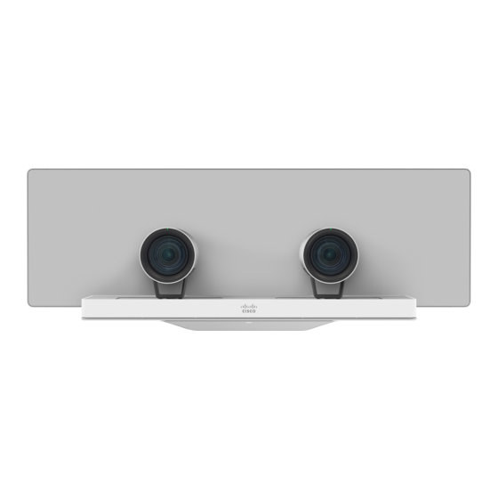
Cisco SpeakerTrack 60 Installation Manual
Telepresence
Hide thumbs
Also See for SpeakerTrack 60:
- Manual (22 pages) ,
- Installation manual (19 pages) ,
- Datasheet (3 pages)
Table of Contents
Advertisement
Quick Links
Advertisement
Table of Contents

Summary of Contents for Cisco SpeakerTrack 60
- Page 1 Cisco TelePresence SpeakerTrack 60 INSTALLATION GUIDE The SpeakerTrack 60 uses a unique dual-camera technique to quickly view a close-up of the active speaker in the meeting room. 78-100223-02E0 | OCTOBER 2016. Copyright © 2016 Cisco Systems, Inc. All rights reserved.
-
Page 2: Installation
Installation We invite you to explore the Project Workplace guide to inspire you on room design and room setup. Go to: www.cisco.com/go/projectworkplace Main box contents 1 × Cover plate 1 × Microphone panel with four biult-in microphones 2 × Precision 60 Camera 1 ×... -
Page 3: Safety Instructions
Safety instructions WARNING: Use Ethernet cable only when connecting to the Ethernet port on the camera. Do not connect a serial VISCA cable to the Ethernet port on the camera, as this will cause severe damage to the camera. NOTE •... - Page 4 Microphone range The participants should be seated within the maximum microphone range. For optimal audio tracking the SpeakerTrack 60 should be mounted at some distance from the side walls. Minimum distance to the side walls 120 cm / 47.25 in...
- Page 5 Option 1: Mount the camera on the wall The SpeakerTrack 60 can be mounted above or below the monitor. For large monitors (70” and above), we recommend mounting the SpeakerTrack 60 below the monitor. Select a mounting height for SpeakerTrack 60 that provides clear line of sight, to all four edges of the microphone panel, from all appropriate positions in the meeting room.
- Page 6 To achieve this, the recess should have slanted walls*. SpeakerTrack 60 mounted in a recess above the monitor 82 cm (32.3 in) 32 cm (12.6 in)
- Page 7 Template Page 1 Template Page 2 Template for attaching wall bracket for SpeakerTrack 60 Gabarit de fixation du support mural pour SpeakerTrack 60 Check that the unit is level. Find the center point of the Vérifiez que l’appareil est à niveau.
-
Page 8: Mount The Base Unit
Mount the base unit Place the microphone panel (B) on a clean and stable surface (for example a table) with the microphone cables headed up and the textile headed down. Use the supplied gloves (L). Remove the cover plate (A) from the base unit before this operation. - Page 9 (typically if a Touch device is connected) you will need a network switch. Connect the switch to the Ethernet port on the codec, and connect the Touch device and SpeakerTrack 60 to the switch. We recommend using a Cisco switch. Connect the short Ethernet and...
- Page 10 Mount the assembly to the wall Hold and lift the unit as illustrated. Carefully place the unit onto the wall bracket. Check that the unit is level. If not, you can adjust the unit sideways. Mount the interface plate to the cameras Place the camera (C) on a stable surface as illustrated.
-
Page 11: Connect The Camera Cables
Connect the camera cables It can be a bit cramped when you connect and secure the cameras, so you’ll probably want to inspect the camera connector panel to know where the HDMI, Ethernet and power are located. 3,0A The Ethernet and power Connect one HDMI cable cables are coming from the to each camera. - Page 12 Fasten the cameras Make sure the pins on the base plate fits the holes in the camera interface plate. Use the thumb nut (O) to attach the camera to the base. Repeat this step for the second camera. Make sure the pins on the base plate fits the holes in the camera interface plate.
-
Page 13: User Documentation And Support
Connect the power cable to the power mains. HDMI Ethernet Power HDMI left right camera camera User documentation and support User documentation for SpeakerTrack 60: http://www.cisco.com/go/telepresence/docs Navigate to: Collaboration Endpoints > Collaboration Peripherals > TelePresence Peripherals > TelePresence SpeakerTrack 60 For support, go to: http://www.cisco.com/support... - Page 14 For a list of offices, visit the Cisco website at http://www.cisco.com/go/offices Cisco and the Cisco logo are trademarks or registered trademarks of Cisco and/or its affiliates in the U.S. and other countries. To view a list of Cisco trademarks, go to this URL: www.cisco.com/go/trademarks.


Need help?
Do you have a question about the SpeakerTrack 60 and is the answer not in the manual?
Questions and answers