Table of Contents
Advertisement
Advertisement
Table of Contents

Related Manuals for Thrane&Thrane TT-6007A


Summary of Contents for Thrane&Thrane TT-6007A
- Page 1 INSTALLATION MANUAL TT-6006A and TT-6007A Message terminal...
- Page 3 TT-6006A and TT-6007A Message Terminal Installation manual Document number: 98-130088-B Release date: March 16, 2010...
- Page 4 Disclaimer Any responsibility or liability for loss or damage in connection with the use of this product and the accompanying documentation is disclaimed by Thrane & Thrane. The information in this manual is provided for information purposes only, is subject to change without notice and may contain errors or inaccuracies.
- Page 5 Safety summary The following general safety precautions must be observed during all phases of operation, service and repair of this equipment. Failure to comply with these precautions or with specific warnings elsewhere in this manual violates safety standards of design, manufacture and intended use of the equipment.
- Page 6 About the manual Intended readers This manual is an installation manual for the Message Terminal. The manual is intended for installers of the Message Terminal and service personnel. Personnel installing or servicing the system must be properly trained and authorized by Thrane & Thrane. It is important that you observe all safety requirements listed in the beginning of this manual, and install the system according to the guidelines in this manual.
-
Page 7: Table Of Contents
Table of Contents Chapter 1 Installation In this chapter ..............1 The Message Terminal ............2 Initial inspection ..............4 Installation .................5 Storage ................7 Repacking for shipment .............7 Chapter 2 Connectors and controls In this chapter ..............9 Connectors ............... 10 Buttons in the front panel ..........23 App. - Page 8 Table of Contents Glossary ..................33 Index ..................37...
-
Page 9: Chapter 1 Installation
Chapter 1 Installation In this chapter This chapter provides a short description of the two types of Message Terminal, including descriptions of: • The Message Terminal • Initial inspection • Installation • Storage and • Repacking for shipment... -
Page 10: The Message Terminal
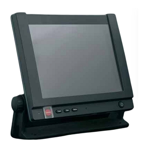
GMDSS or general purpose terminal There are two variants of the Message Terminal: The TT-6006A and the TT-6007A. The only visible difference is the Distress button on the TT-6006A, which is a GMDSS approved terminal. The next sections describe the two terminals. - Page 11 Chapter 1: Installation TT-6007A The TT-6007A Message Terminal is a general purpose maritime terminal, e.g. for fishery e-log using third party software. It provides several types of interfaces for connection to external equipment, such as a Mini-C transceiver or BGAN terminal, an ethernet switch and a printer. The Message Terminal has a touch-screen for operating the terminal.
-
Page 12: Initial Inspection
Chapter 1: Installation Initial inspection Warning! To avoid electrical shock, do not apply power to the Message Terminal if there is any sign of shipping damage to any part of the front or rear panel or the outer cover. Read the safety summary at the front of this manual before installing or operating the Message Terminal. -
Page 13: Installation
Chapter 1: Installation Installation Cable requirements All cables attached to the Message Terminal must be shielded. Every shield should have a low impedance connection to an electrical ground. For information on connectors, see Connectors on page 10. Before using the Message Terminal for the first time, check that all cables are correctly wired and fastened. - Page 14 Chapter 1: Installation Flush mount You can flush mount the Message Terminal in a console by using the 4 screw holes (A) on the back of the terminal. The holes are M4 x 10 mm. For a drawing of the Flush-mount plate with panel cut-out and mounting holes, see Outline drawing: Flush mount plate on page 31.
-
Page 15: Storage
Chapter 1: Installation Storage The Message Terminal may be stored or shipped in temperatures between -40° C and +80° C. Protect the Message Terminal from extreme temperature variation which can cause condensation. We recommend that you unpack the Message Terminal immediately on delivery. - Page 16 Chapter 1: Installation Repacking for shipment...
-
Page 17: Chapter 2 Connectors And Controls
Chapter 2 Connectors and controls In this chapter This chapter provides a description of all connectors and controls on the Message Terminal. It has the following sections: • Connectors • Buttons in the front panel... -
Page 18: Connectors
Chapter 2: Connectors and controls Connectors Overview The drawing below shows the connectors on the Message Terminal. NMEA 183 Talker Handset or Hand microphone DC Power input RS-232 4 x USB Ethernet 2 x NMEA 183 Listener Memory card Stereo audio holder SDHC output Ground... - Page 19 Chapter 2: Connectors and controls USB interface Overview There are four USB Host interface ports (USB Type A) in the rear panel of the Message Terminal and one at the bottom of the front panel. The applications for the USB ports are as follows: Front panel USB port: Temporary connection of mass storage devices •...
- Page 20 Chapter 2: Connectors and controls Pin-out The USB connectors are USB Type A. The figure and table below show the connector outline, wire colors and pin assignments. USB Type A socket Pin number Pin function Wire color White Green Black Connectors...
- Page 21 Chapter 2: Connectors and controls Ethernet interface Overview There is one Ethernet (10/100 MB) connector on the rear panel of the Message Terminal. The Ethernet interface can be used for communicating with connected equipment, such as a TT-6081A power supply or an alarm panel. Pin-out The figure and table below show the connector outline, pin assignments and wire color.
- Page 22 Chapter 2: Connectors and controls RS-232 interface (X1) overview There is one RS-232 DTE connector on the rear panel of the terminal. Pin-out The figure and table below show the connector outline and pin assignments. Pin number Pin function D-Sub, 9 pin male Not Connected RxD (Receive Data) Input TxD (Transmit Data) output...
- Page 23 Chapter 2: Connectors and controls NMEA 0183 compatible Talker interface (X2) Overview The NMEA 0183 compatible Talker interface complies to IEC 61162-1 and IEC 61162-2. You can select between two speeds: 4800 or 38400 Baud. Note The NMEA 0183 compatible Talker connector is a custom connector; a matching cable with connector is available from Thrane &...
- Page 24 Chapter 2: Connectors and controls Accessory interface (X3) Overview The Accessory interface connects to e.g. the TT-6201 Handset and the TT-6202 Hand microphone. Pin-out The figure and table below show the connector outline and pin assignments. Panel lock, 10 pin male Pin number Pin function MIC+...
- Page 25 Chapter 2: Connectors and controls DC Power input (X4) Overview The DC Power input connects to a DC supply with 12 to 24 V DC nominal (10.8 to 32 V DC). The interface also has a “remote on/off” function and an “on/off control”...
- Page 26 Chapter 2: Connectors and controls Connecting DC power Connect DC+ (red wire) to DC out + from your DC supply. Connect DC- (black wire) to DC out - from your DC supply. Do not connect the white wire nor the blue wire in the power cable, unless you want to use the Remote on/off function or the On/off control function.
- Page 27 Chapter 2: Connectors and controls CAN-bus interface (X5) Overview The CAN-bus interface in the Message Terminal supports bidirectional communication. Note The CAN-bus connector is a custom connector; a matching cable with connector is available from Thrane & Thrane. Pin-out The figure and table below show the connector outline, pin assignments and standard wire colors.
- Page 28 Chapter 2: Connectors and controls NMEA 0183 compatible Listener interface (X6 and X7) Overview The Message Terminal has two NMEA 0183 compatible Listener interfaces, one high speed (X6: 4800/38400 Baud) and one low speed (X7: 4800 Baud). Note The NMEA 0183 compatible Listener connector is a custom connector;...
- Page 29 Chapter 2: Connectors and controls Memory card holder, SDHC Overview The Message Terminal has a slot where you can insert a memory card of the type SDHC (Secure Digital High Capacity). The memory card slot is located at the bottom of the terminal next to the front USB connector. Connectors...
- Page 30 Chapter 2: Connectors and controls Ground stud Important You must connect the Ground stud to ship ground. The ground stud is located in the connector panel and is used to connect a ground wire for grounding the Message Terminal. To connect the Message Terminal to ship ground, do as follows: 1.
-
Page 31: Buttons In The Front Panel
Chapter 2: Connectors and controls Buttons in the front panel Overview The drawing below shows the buttons on the Message Terminal. Note Only TT-6006A has a Distress button. It is not available on TT-6007A. Distress Test Mute Power button button... - Page 32 Chapter 2: Connectors and controls Functions of the buttons The buttons in the front panel have the following functions: Control Function Distress (only The Distress button on the TT-6006A Message Terminal on TT-6006A) is used in safety systems to send a distress message through a connected transceiver.
-
Page 33: In This Chapter
Appendix A Specifications In this chapter This chapter provides general specifications for the Message Terminal. General specifications Item Specifications • Intel atom based CPU • SSD (Solid State Drive) for operating system (GNU/Linux or Windows XP embedded), application software and data storage. - Page 34 Appendix A: Specifications Item Specifications • 4 USB Host interface ports - one for printer, one for keyboard Interfaces and 2 for general use (all up to 480 MB). • 1 USB port (front) for external storage (up to 12 MB). •...
-
Page 35: In This Chapter
Appendix B Mechanical outlines In this chapter This chapter shows outline drawings with the dimensions and weight of the Message Terminal. -
Page 36: Outline Drawing: Bottom, Front And Top
Appendix B: Mechanical outlines Outline drawing: Bottom, front and top 268.8 299.6 NOTE: Distress button only on TT-6006A Outline drawing: Bottom, front and top... -
Page 37: Outline Drawing: Rear
Appendix B: Mechanical outlines Outline drawing: Rear 251.2 Weight: 2.0 kg without mounting bracket and wheel knobs Total weight: 2.2 kg A: 4 pcs. M4 x 10 All units are in millimeters Outline drawing: Rear... -
Page 38: Outline Drawing: Side And Perspective View
Appendix B: Mechanical outlines Outline drawing: Side and perspective view 59.9 Outline drawing: Side and perspective view... -
Page 39: Outline Drawing: Flush Mount Plate
Appendix B: Mechanical outlines Outline drawing: Flush mount plate 251.2 All units are in millimeters Outline drawing: Flush mount plate... -
Page 40: Outline Drawing: Cable Relief Plate
Appendix B: Mechanical outlines Outline drawing: Cable Relief Plate Outline drawing: Cable Relief Plate... - Page 41 Glossary Glossary BGAN Broadband Global Area Network. A satellite network based on geostationary satellites, delivering data rates of up to 492 kbps to virtually any part of the earth, with full UMTS (3G) compatibility. Controller-Area Network. A vehicle bus standard designed to allow microcontrollers and devices to communicate with each other within a vehicle without a host computer.
- Page 42 Glossary A computer operating system composed entirely of free software. Its name is a recursive acronym for “GNU’s Not Unix!” This name was chosen because GNU’s design is Unix-like, but differs from Unix by being free software and containing no Unix code. High Frequency.
- Page 43 Glossary Medium Frequency. Radio frequencies (RF) in the range of 300 kHz to 3 MHz. Navtex, which is part of the current Global Maritime Distress Safety System occupies 518 kHz and 490 kHz for important digital text broadcasts. NMEA National Marine Electronics Association (standard). A combined electrical and data specification for communication between marine electronic devices such as echo sounder, sonars, anemometer (wind speed and direction), gyrocompass, autopilot,...
- Page 44 Glossary Thin Film Transistor. A thin film transistor liquid crystal display (TFT-LCD) is a variant of liquid crystal display (LCD) which uses thin-film transistor (TFT) technology to improve image quality (e.g., addressability, contrast). Universal Serial Bus. A specification to establish communication between devices and a host controller (usually personal computers).
- Page 45 Index Index desktop mounting, 6 Dim button, 24 Accessory connector, 16 Distress button, 24 document number this manual, i drawings outline, 27 buttons in front panel, 23 Dim, 24 Distress, 24 Mute, 24 Power, 24 Ethernet connector, 13 Test, 24 flush mount, 6 cable relief front panel buttons, 23...
- Page 46 2 types of, 2 Test button, 24 mounting TT-6006A description, 2 cable relief plate, 5 TT-6007A description, 3 flush mount, 6 types of Message Terminal, 2 on wall or desktop, 6 Mute button, 24 unpacking, 4 USB connectors, 11...
- Page 48 98-130088-B Thrane & Thrane A/S info@thrane.com www.thrane.com • •...
Need help?
Do you have a question about the TT-6007A and is the answer not in the manual?
Questions and answers