Table of Contents
Advertisement
Advertisement
Table of Contents

Related Manuals for Thrane&Thrane TT-3606E


Summary of Contents for Thrane&Thrane TT-3606E
- Page 1 Message Terminal TT-3606E Installation and Service Manual...
- Page 3 Thrane & Thrane Message Terminal TT-3606E Installation and Service Manual Copyright © Thrane & Thrane A/S ALL RIGHTS RESERVED...
- Page 4 Information in this document is subject to change without notice and does not represent a commitment on the part of Thrane & Thrane A/S. © 2007 Thrane & Thrane A/S. All right reserved. Printed in Denmark. Document Number TT98-109638-B. Release Date: 19 March 2007...
- Page 5 DO NOT SUBSTITUTE PARTS OR MODIFY EQUIPMENT Because of the danger of introducing additional hazards, do not substitute parts or perform any unauthorized modification to the equipment. COMPASS SAFE DISTANCE Minimum safety distance of 50 cm from the TT-3606E Message Terminal...
- Page 6 This page is intentionally left blank...
-
Page 7: Table Of Contents
3 Service....................3-1 3.1 Disassembling................3-1 3.2 Configuration ................3-3 4 Technical description................4-1 4.1 Detailed specification ............. 4-1 4.2 Special I/O................4-3 5 Mechanical outlines ................5-1 5.1 TT-3606E ................5-1 5.2 Flush mount................5-3 5.3 Mounting bracket..............5-4 19Mar07 Page i... - Page 8 Table of Contents This page is intentionally left blank Page ii 19Mar07...
-
Page 9: Installation
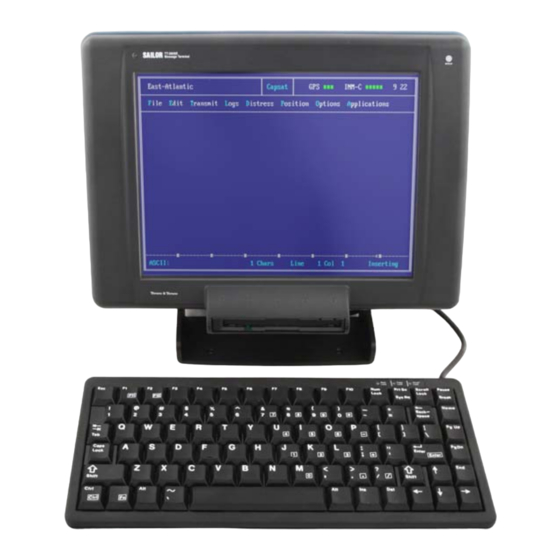
Quick system connect and checkout Installation 1 Installation This chapter provides specific information about installation of the TT-3606E Message Terminal information about initial inspection, storage and repacking for shipment. Figure 1 TT-3606E Message Terminal 19Mar07 Page 1-1... -
Page 10: Quick System Connect And Checkout
Installation Quick system connect and checkout 1.1 Quick system connect and checkout The following brief outline may be used to get the TT-3606E Message terminal up and running • Unpack system components • Connect the keyboard to the TT-3606E •... -
Page 11: Initial Inspection
Initial inspection Installation 1.2 Initial inspection WARNING To avoid hazardous electrical shock, do not perform electrical tests if there is any sign of shipping damage to any portion of the front or rear panel or the outer cover. Read the safety summary at the front of this manual before installing or operating the 3606E Message Terminal. -
Page 12: Storage
Installation Storage 1.3 Storage The 3606E may be stored or shipped in temperatures within the limits -40° C to +80° C. It is advisable to protect 3606E from extreme temperature variation which can cause excessive condensation. It is recommended that the 3606E is unpacked immediately on delivery. Page 1-4 19Mar07... -
Page 13: Repacking For Shipment
Repacking for shipment Installation 1.4 Repacking for shipment The shipping carton for the 3606E has been carefully designed to protect the Message Terminal and its accessories during shipment. This carton and its associated packing material should be used when repacking for shipment. Attach a tag indicating the type of service required, return address, model number and full serial number. -
Page 14: Cabling
Before using the TT-3606E Message Terminal for the first time check out that all cables are correctly wired and fastened. Please notice that the DC-input range applies to the DC voltage measured at the pin's on the power connector on the 3606E. -
Page 15: Mounting
Message Terminal it is important that the small indications on the cylinders are in-line with the indications on the rear of TT-3606E Message Terminal. When installing the TT-3606E on a vertical surface it is necessary to mount the mounting bracket opposite the way it is mounted for horizontal installation. - Page 16 Installation Mounting This page is intentionally left blank Page 1-8 19Mar07...
-
Page 17: Description
Mounting Description 2 Description This chapter describes the TT-3606E Message Terminal. This encompasses specifications as well as provides specific information about the available features and interfaces. 19Mar07 Page 2-1... -
Page 18: Specifications
ISO/R 694, Method B) Dimensions H x W x D 221x 297 x 114.5 mm w/o bracket 256 x 297 x 114.5 mm w bracket at vertical position Weight 3.1 kg (including mounting bracket) Table 1 TT-3606E Message Terminal Page 2-2 19Mar07... -
Page 19: Connectors
Connectors Description 2.2 Connectors This section describes the functions and pin assignments of connectors found on the rear of the TT-3606E. Figure 2 shows the connector part of the TT-3606E Message Terminal. Figure 2 Rear connectors 2.2.1 Keyboard connector The figure below indicates the pin assignment of the keyboard connector as seen from the rear of the TT-3606E Message Terminal. -
Page 20: Power Connector
2.2.2 Power connector The power input connector is a standard 15 pin SubD male connector, located on the rear panel of the TT-3606E and the pin assignments are as indicated below. The Remote ON/OFF input makes it possible to place an eventual on/off switch at any location. -
Page 21: Parallel Printer Port
Connectors Description 2.2.3 Parallel printer port The parallel printer port is a standard 25 pin SubD female connector, located on the rear panel of the TT-3606E and the pin assignments are as indicated below. Name Signal Description STRB Strobe DAT0... -
Page 22: Serial Ports
Description Connectors 2.2.4 Serial ports The serial ports are standard 9 pin SubD male connectors, located on the rear panel of the TT-3606E and the pin assignments are as indicated below. Name Direction Signal Description input Data Carrier Detect input... -
Page 23: Service
This chapter describes how to disassemble and to service to a level of changing boards/parts. 3.1 Disassembling If you have to disassemble the TT-3606E Message Terminal it is important, that you follow the procedure described in this section. Otherwise you will find it very difficult and you risk to permanently damage the Message Terminal. - Page 24 Service Disassembling To get access to the main PCB, backlight PCB (piggy bag on the main PCB) and computer board the following steps should be followed: WARNING To avoid hazardous electrical shock, do not touch the two high voltage outputs of the backlight inverter.
-
Page 25: Configuration
Configuration Service 3.2 Configuration The main PCB, which is shown in figure 4, contains the following jumpers, measurement points and adjustment possibilities: Reference Factory setting or Function value/range Open If closed the computer is reset Closed Connecting/disconnecting power supply from rest of circuitry 120 kHz, ±... - Page 26 Service Configuration W2 pin Function + 12 V DC, ± 20 % Ground + 5 V DC, ± 10 % No Connection Table 6 Jumper W2 The CMOS-setup in the computer may be reset to default by moving the jumper marked “CLEAR CMOS” on the computer board from position 1-2 to position 2-3 and then back to position 1-2.
- Page 27 Configuration Service Figure 4 Main PCB 19Mar07 Page 3-5...
- Page 28 Service Configuration This page is intentionally left blank Page 3-6 19Mar07...
-
Page 29: Technical Description
Detailed specification Technical description 4 Technical description This chapter gives a detailed description of the TT-3606E Message Terminal. 4.1 Detailed specification The hardware platform of TT-3606E Message Terminal is PC - compatible. The table below gives a more detailed specification of the computer part. - Page 30 Technical description Detailed specification Figure 5 shows the physical outline of the computer board: Figure 5 Computer board Page 4-2 19Mar07...
-
Page 31: Special I/O
Special I/O Technical description 4.2 Special I/O Special I/O ports have been implemented in the TT-3606E Message Terminal in order to be able to support some extra features compared to a standard PC. These are • Disk change signal from floppy •... - Page 32 Technical description Special I/O The “disk change signal “ is a hardware signal from the floppy drive which during access to the floppy indicates (goes to 0) whether or not the floppy has been changed. Can be used in the application software to only read the FAT-table, when the floppy has actual changed.
- Page 33 Special I/O Technical description The reset possibility of the external keyboard can be used by the application software for keyboard surveillance purposes. The display backlight is controlled using electronic potentiometers controlled using three signals: CS : Chip Select /INC: Increment /DWN: Up/down selection If CS is “1”...
- Page 34 Technical description Special I/O In order to completely turn off the backlight it is necessary to use the display backlight on/off bit and set it to 1. A way to cope with the display backlight characteristic is to have two display setups/styles: one used during daylight (bright colors, but not red) and one used during night (red characters and graphics on a black background).
- Page 35 Special I/O Technical description This page is intentionally left blank 19Mar07 Page 4-7...
-
Page 37: Mechanical Outlines
This chapter shows the dimensions of the TT-3606E Message Terminal as well as the mounting stencils for the different ways of mounting the TT-3606E Message Terminal. 5.1 TT-3606E Figure 6 and 7 shows the dimensions of the TT-3606E Message Terminal. Figure 6 TT-3606E Message Terminal... - Page 38 Mechanical outlines Figure 7 TT-3606E Message Terminal Page 5-2 19Mar07...
-
Page 39: Flush Mount
Index 5.2 Flush mount Figure 8 indicates the dimension of the panel cut-out and position of mounting holes when mounting the TT-3606E Message Terminal in a consol. Figure 8 TT-3606E Message Terminal 19Mar07 Page 5-3... -
Page 40: Mounting Bracket
Mechanical outlines 5.3 Mounting bracket Figure 9 indicates the position of the mounting holes for the mounting bracket. Figure 9 TT-3606E Message Terminal Page 5-4 19Mar07...
Need help?
Do you have a question about the TT-3606E and is the answer not in the manual?
Questions and answers
The message "SPI Loader version 1.06,5-Ferruary-2010 Loading A ......" are displayed on the Sailor TT-3606EE message terminal' screen, cannot return to Capsat desktop
The message "SPI Loader version 1.06, 5-February-2010 Loading A ......" on the Thrane&Thrane Sailor TT-3606E terminal screen indicates that the terminal is in bootloader mode, attempting to load firmware.
To resolve this and return to the Capsat desktop, a firmware reload is usually required. This involves connecting the terminal to a PC and using the appropriate software tools to reinstall the correct firmware. If the issue persists, the terminal may need service or repair.
This answer is automatically generated