Table of Contents
Advertisement
Quick Links
Advertisement
Table of Contents

Related Manuals for Adamson S-SERIES


Summary of Contents for Adamson S-SERIES
- Page 2 Directive 2006/42/EC: Machinery Directive 973-0003 S10 973-0004 S10i 994-0002 S119 994-0004 S119i 930-0020 S-Series Support Frame 930-0024 S-Series Install Support Frame 930-0021 S-Series Extended Beam 931-0010 S10 Underhang 938-0019 S10 Dolly 938-0021 S119 Dolly 938-0014 Dolly Stacking Legs E-Series | Declaration of Conformity...
- Page 3 INSTRUCTIONS AT TENTION It is compulsory to read this manual before using the S-Series system. Supervision and competency are the responsibility of the system owners and operators. All intersections, joints and rigging hard- ware must be inspected regularly. Operators must not assume rigging has been inspected prior to use by someone else.
-
Page 4: S-Series | Safety Precautions
Schützen Sie die Lautsprecherkabel davor gequetscht oder geknickt • Utilice solamente los Rigging Frames y accesorios especificados zu werden. por Adamson o que vengan con el equipo original de Adamson. • Verwenden Sie ausschließlich das von Adamson für dieses •... -
Page 5: Table Of Contents
3.3 Setting Angles 3.4 Attaching the Rigging Frame 3.5 Extender Beam 3.6 Single Point Rigging 3.7 Ground Stacking 3.8 Lowering the Array 3.9 Rigging the S119 3.10 Installation Rigging Accessories 4.0 Ground Stacking Legs S-Series | Table of Contents Page 5... -
Page 6: Introduction & Product Details
This manual is designed to give the S-Series user the necessary information to accurately fly or stack S-Series loudspeakers in all the available configurations, as well as the proper deployment and use of S-Series loudspeakers. Safe step by step rigging procedures will be outlined, as well as example system configurations, correct wiring and amplification and transport. -
Page 7: Predictive Software
Blueprint AV is a 2D & 3D modeling suite which offers a fast and intuitive work-flow, without sacrificing precision. The S-Series is included, along with all of Adamson’s other Line Array products. Design is simple and easy, yet complex simulation options are at your finger tips. -
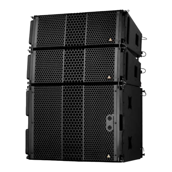
Page 8: S10 Spec Sheet
Maximum Peak SPL ** 141.3 dB Components LF 2x ND10-LM 10” Kevlar Neodymium Driver Components HF Adamson NH4TA2 4” Diaphragm / 1.5” Exit Compression Driver Nominal Impedance LF 2 x 16 Ω (8 Ω) 737 mm / 29 in Nominal Impedance HF 8 Ω... -
Page 9: S119 Spec Sheet
The S119 Subwoofer is the companion subwoofer to the S10. The enclosure is loaded with a light weight, long excursion, 19” ND19 Kevlar Neodymium driver utilizing Adamson’s Advanced Cone Architecture and a 5” voice coil for exceptional power handling. It is mounted in an ultra-efficient front-loaded enclosure, designed to reproduce clean, musical low frequency information. -
Page 10: Cardioid Subs
Introduction & Product Details 1.7 Cardioid Subs Every Adamson subwoofer has specifically designed cardioid presets. Adamson utilizes three configurations ranging from a minimal footprint and minimized rear rejection to larger setups that eliminate virtually all audio energy behind the array. Please refer to the Lake Preset Loading Manual for further instructions. -
Page 11: System Configuration
• Up to three Lab.gruppen PLM 12K44 amplifiers (8 and 12-Channel versions available) • Adamson Audio Panel • Adamson AC Panel, 120 V or 230 V (region specific) • Cisco SG300-20 managed switch • Includes one Personal License per rack... -
Page 12: E-Rack Overview
System Configuration 2.1 E-Rack Overview Adamson has developed a unified rack solution configured to interface seamlessly with our line of Loudspeaker products. For more information on the E-Rack, please refer to the E-Rack brochure available on the Adamson Systems website. -
Page 13: Configuration Example
System Configuration 2.2 Configuration Example This example configuration demonstrates the efficiency of the system. For further information re- garding configurations, please refer to the Adamson Document S-Series Configuration Brochure. PUSH PUSH PUSH PUSH PUSH PUSH PUSH PUSH PUSH PUSH PUSH... -
Page 14: Wiring Diagrams
LMF - 2x 10” ND10-LM[940-0025], HF - 1x 4”NH4TA2 [140-0020] SlideLock™ rigging system PARALLEL INPUTS ORANGE THRU PURPLE ORANGE THRU PURPLE YELLOW BLUE BLACK S119 Subwoofer [994-0002] LF - 1x 19” ND19, SlideLock™ rigging system S-Series | Wiring Diagrams Page 14... -
Page 15: Pin Swap Cable
System Configuration 2.4 Pin Swap Cable A single PLM + amplifier can drive up to 8x S10 enclosures, so long as the NL803 Pin Swap Cable (920-0024) is utilized. This cable is marked with red heat shrink to distinguish it from other NL8 links in a user’s inventory. - Page 16 System Configuration 2.4 Pin Swap Cable Below is a description of how to cable subwoofers when using all four channels of the PLM + am- plifier as subwoofer channels. E-Rack to Parallel Output to Output to Parallel Parallel PUSH PUSH PUSH PUSH PUSH...
-
Page 17: Rigging
There is a tip hazard when transporting a 4 stack on uneven ground or on a ramp. To avoid tipping the dolly, It should always travel with sides of the cabinet to the front or back. *On the 4 stack dolly, the bottom cabinet is held in place by the rear, blue push-pin.. S-Series | Rigging Page 17... -
Page 18: Rigging Overview
(Fig. 2) The following rigging positions are equal to the following degrees for the S10 (Fig. 1) 0° 1° 2° 3° 4° 5° 6° 6.9° 10° Storage in enclosure Fig. 1 Fig. 2 S-Series | Rigging Page 18... - Page 19 ATTENTION IMPORTANT OPERATING INSTRUCTIONS The S-Series Support Frame is designed for use with all S-Series enclosures. It consists of a steel frame and can be paired with the S-Series Extender Beam. Always refer to Blueprint AV™ for correct rigging instructions.
- Page 20 3.1 Rigging Overview ATTENTION IMPORTANT OPERATING INSTRUCTIONS For arrays with little to no incline, the S-Series Extender Beam centered will usually provide the best weight dispersion. For arrays with negative incline, the S-Series Extender Beam positioned towards the back of the frame will provide the best weight dispersion.
-
Page 21: Rigging Sticker Legend
* The S-Series Stacking Pin is to be used when needing to maintain rigid angles either with a ground-stacked array, or an array with a high amount of positive tilt. To engage the Stacking Pin, bring the enclosure to its intended rigging position limit, press the Stacking Pin in and turn clockwise. -
Page 22: Setting Angles
Blueprint AV design. (Fig. 2) Fig. 2 3. Place the angle pin in the coloured slot that corresponds to the sliding knob position. (Fig. 3) Fig. 3 4. Repeat for all enclosures. (Fig. 4) Fig. 4 S-Series | Rigging Page 22... -
Page 23: Attaching The Rigging Frame
PERSONAL INJURY The S-Series Support Frame contains 4 link points, all of which need to be attached to the top enclosure in your array. The system ideally uses 2 motors: one in front, one in back of the frame for easy adjustment once the array has been flown. - Page 24 (Fig. 6) Fig. 6 7. Place the rear link pin to affix the S-Series Support Frame (Fig. 7) Fig. 7 8. The S-Series Support Frame is now attached and ready for plate configuration.
-
Page 25: Extender Beam
PAY SPECIAL ATTENTION PERSONAL INJURY When using a highly curved or steeply tilted array, using the S-Series Extender Beam is necessary. Below are the steps needed to attach the Beam to the S-Series Support Frame. 1. Remove the Lifting Plates from the S-Series Support Frame and pin in place the Extender Beam Plates at either end of the support frame.(Fig. -
Page 26: Single Point Rigging
PERSONAL INJURY If only one motor is available, moderately curved and tilted arrays can be lifted using only the S-Series Support frame. The same procedure can be implemented using the Extender Beam for arrays with a greater angular and tilt characteristics. -
Page 27: Ground Stacking
3. Remove the bottom link pin from the S10 to be ground stacked. (Fig. 3) Fig. 3 4. Place the bottom link pin back in the S10 to maintain the rigging piece’s rigidity. (Fig. 4) Fig. 4 S-Series | Rigging Page 27... - Page 28 Fig. 6 7. Secure the front rigging pieces with the S119 top front link pins. (Fig. 7) Fig. 7 8. Secure the rear rigging pieces with the S10 bottom back link pins. (Fig. 8) Fig. 8 S-Series | Rigging Page 28...
- Page 29 (Fig. 10) Fig. 10 11. With the stacking pins engaged, the array will maintain the intended angles. (Fig. 11) Fig. 11 12. Repeat as needed to reach the desired enclosure count. (Fig. 12) Fig. 12 S-Series | Rigging Page 29...
-
Page 30: Lowering The Array
5. Remove all connecting link pins. Fig. 5 6. Lift the array above the 4 stack (Fig. 5) 7. Wheel 4 stack out of the way Repeat procedure until done. (Fig. 6) Fig. 6 S-Series | Rigging S-Series | Rigging Page 30... -
Page 31: Rigging The S119
The S119 can be rigged in the same array as the S10 without the use of any adapter rigging pieces. Affixing the S-Series Support Frame to the S119 is completed in the same manner as described in section 3.4, by using rigging position 4 on the top S10 cabinet in the stack. - Page 32 Rigging 3.9 Rigging the S119 PINCH POINT WARNING CAN CAUSE SEVERE SAFETY RISK PAY SPECIAL ATTENTION PERSONAL INJURY 5. Keep lowering the S119 until the S10 rear rigging pieces slide into the S119 rear rigging channels. (Fig. 5) Fig. 5 6.
-
Page 33: Installation Rigging
PAY SPECIAL ATTENTION PERSONAL INJURY The S-Series Install Frame is designed for use with all S-Series Installation enclosures. It is the same frame as the standard frame, but with the addition of two rear rigging links. It consists of a steel frame and can be paired with the S-Series Extender Beam. - Page 34 Rigging 3.10 Installation Rigging PINCH POINT WARNING CAN CAUSE SEVERE SAFETY RISK PAY SPECIAL ATTENTION PERSONAL INJURY The S10i rear rigging consists of a positioning system and a rigging link. (Fig. 1) An alpha- numerical chart is printed on the positioning sticker to determine rigging position.
- Page 35 Rigging 3.10 Installation Rigging PINCH POINT WARNING CAN CAUSE SEVERE SAFETY RISK PAY SPECIAL ATTENTION PERSONAL INJURY Correct position of the front rigging link The S10i front rigging utilizes a front rigging link. The link consists of three connection points, two on the top and one on the bottom.
-
Page 36: Accessories
7. If a negative inclination is desired, tighten the back two stacking legs until desired incline is achieved. 8. If a positive inclination is desired, tighten the front two stacking legs until desired incline is achieved. Fig. 2 Fig. 3 Fig. 4 S-Series | Ground Stacking Configuration Page 36...
Need help?
Do you have a question about the S-SERIES and is the answer not in the manual?
Questions and answers