Table of Contents
Advertisement
Operator's Manual
™
Fleet
500
Register your machine:
www.lincolnelectric.com/register
Authorized Service and Distributor Locator:
www.lincolnelectric.com/locator
Save for future reference
Date Purchased
Code: (ex: 10859)
Serial: (ex: U1060512345)
IM10349
| Issue D ate Feb-16
© Lincoln Global, Inc. All Rights Reserved.
For use with machines having Code Numbers:
12511
Need Help? Call 1.888.935.3877
to talk to a Service Representative
Hours of Operation:
8:00 AM to 6:00 PM (ET) Mon. thru Fri.
After hours?
Use "Ask the Experts" at lincolnelectric.com
A Lincoln Service Representative will contact you
no later than the following business day.
For Service outside the USA:
Email: globalservice@lincolnelectric.com
Advertisement
Table of Contents

Related Manuals for Lincoln Electric Fleet 500


Summary of Contents for Lincoln Electric Fleet 500
- Page 1 Operator’s Manual ™ Fleet For use with machines having Code Numbers: 12511 Need Help? Call 1.888.935.3877 Register your machine: to talk to a Service Representative www.lincolnelectric.com/register Authorized Service and Distributor Locator: Hours of Operation: www.lincolnelectric.com/locator 8:00 AM to 6:00 PM (ET) Mon. thru Fri. Save for future reference After hours? Use “Ask the Experts”...
- Page 2 THANK YOU FOR SELECTING A QUALITY PRODUCT BY KEEP YOUR HEAD OUT OF THE FUMES. DON’T get too close to the arc. LINCOLN ELEC TRIC. Use corrective lenses if necessary to stay a reasonable distance away from the arc. READ and obey the Safety Data PLEASE EXAMINE CARTON AND EQUIPMENT FOR Sheet (SDS) and the warning label DAMAGE IMMEDIATELY...
- Page 3 MAGNETIC FIELDS MAY W117.2-1974. A Free copy of “Arc Welding Safety” booklet BE DANGEROUS E205 is available from the Lincoln Electric Company, 22801 St. Clair Avenue, Cleveland, Ohio 44117-1199. 2.a. Electric current flowing through any conductor BE SURE THAT ALL INSTALLATION, OPERATION, causes localized Electric and Magnetic Fields (EMF).
-
Page 4: Electric Shock Can Kill
S FETY ELECTRIC SHOCK ARC RAYS CAN BURN. CAN KILL. 3.a. The electrode and work (or ground) circuits are 4.a. Use a shield with the proper filter and cover plates to protect your electrically “hot” when the welder is on. Do eyes from sparks and the rays of the arc when welding or not touch these “hot”... - Page 5 S FETY WELDING AND CUTTING CYLINDER MAY EXPLODE IF SPARKS CAN CAUSE DAMAGED. FIRE OR EXPLOSION. 7.a. Use only compressed gas cylinders containing the correct shielding gas for the process used 6.a. Remove fire hazards from the welding area. If and properly operating regulators designed for this is not possible, cover them to prevent the welding sparks the gas and pressure used.
-
Page 6: Table Of Contents
TABLE OF CONTENTS INSTALLATION ...........................SECTION A TECHNICAL SPECIFICATIONS ......................A-1 LOCATION AND VENTILATION......................A-2 STACKING............................A-2 ANGLE OF OPERATION ........................A-2 LIFTING............................A-2 HIGH ALTITUDE OPERATION ......................A-2 HIGH TEMPERATURE OPERATION.....................A-2 TOWING............................A-3 VEHICLE MOUNTING.........................A-3 FUEL ............................A-3 ENGINE COOLING SYSTEM .......................A-3 BATTERY CONNECTION........................A-3 MUFFLER OUTLET PIPE........................A-3 SPARK ARRESTER..........................A-3 REMOTE CONTROL .........................A-4 ELECTRICAL CONNECTIONS......................A-4 OPERATION ..........................SECTION B... - Page 7 FLEET™ 500 INSTALLATION teChniCal sPeCiFiCations - Fleet™ 500 (K4338-1) INPUT - DIESEL ENGINE Make/Model Description Speed (RPM) Displacement Starting System Capacities 125 CU. IN FUEL DEUTZ (2.05L) (25 US GAL) D2011L03I 3 CYLINDER IDLE 1890 94.6L 12VDC BATTERY DIESEL ENGINE 32HP (24 KW) &...
-
Page 8: Installation
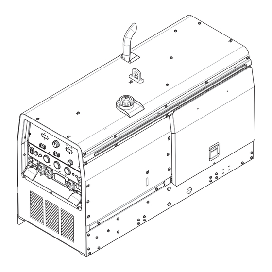
FLEET™ 500 INSTALLATION INSTALLATION liFting The Fleet™ 500 weighs approximately 1410lbs. (639kg.) with a SAFETY PRECAUTIONS empty fuel tank. A lift bail is mounted to the machine and should always be used when lifting the machine. WARNING Liftbale max lifting weight = 2600lbs Do not exceed max lifting weight. -
Page 9: Towing
Use caution as the electrolyte is a strong acid that can burn skin and damage eyes. Improperly mounted concentrated loads may cause The Fleet 500 is shipped with the negative battery cable unstable vehicle handling and tires or other components disconnected. Make certain that the RUN-STOP switch is in the to fail. -
Page 10: Remote Control
FLEET™ 500 INSTALLATION remote Control eleCtriCal ConneCtions Machine Grounding The Fleet™ 500 is equipped with a 6-pin connector. When a remote control is connected to the 6-pin Connector, the auto- Because this portable engine driven welder creates its own power, sensing circuit automatically switches the OUTPUT control from it is not necessary to connect its frame to an earth ground, unless control at the welder to remote control. - Page 11 FLEET™ 500 INSTALLATION Cable Installation residual Current deViCe ready Install the welding cables to your Fleet™ 500 as follows. The Fleet™ 500 is configured to allow for the addition of a 1. The engine must be OFF to install welding cables. Residual Current Device (RCD) to protect the 2-240V Single Phase 2.
-
Page 12: Operation
Engine Instruction Manual. breaK-in Period general desCriPtion Lincoln Electric selects high quality, heavy-duty industrial engines for the portable welding machines we offer. While it is normal to The Fleet™ 500 is a diesel engine powered DC multi-process see a small amount of crankcase oil consumption during initial welding power source and AC power generator. -
Page 13: Welding Controls
FIGURE B.1 FLEET™ 500 OPERATION 4. ARC FORCE- The ARC FORCE dial is active in the PIPE/GOUGE mode when on low range, and in the CC-STICK mode. This welding Controls control is not active in the PIPE/GOUGE mode when in high range (Figure B.1) or when in TIG mode. -
Page 14: Engine Operation
FLEET™ 500 OPERATION 10. ENGINE HOUR METER / FUEL GAUGE- Displays the total time that the engine has been running. This meter is useful for engine oPeration STARTING THE ENGINE scheduling prescribed maintenance. Shows fuel level. 11. ENGINE TEMPERATURE GAUGE- An indicator of engine temperature. -
Page 15: Welder Operation
FLEET™ 500 OPERATION welder oPeration DUTY CYCLE Duty Cycle is the percentage of time the load is being applied in a 10 minute period. For example a 60% duty cycle, represents 6 minutes of load and 4 minutes of no load in a 10 minute period. ELECTRODE INFORMATION For any electrode the procedures should be kept within the rating of the machine. - Page 16 FLEET™ 500 OPERATION TABLE B.3 TYPICAL CURRENT RANGES FOR TUNGSTEN ELECTRODES Tungsten Electrode DCEN (-) DCEP (+) Approximate Argon Gas Flow TIG TORCH Diameter in. (mm) Flow Rate C.F.H. ( l /min.) Nozzle Size (4), (5) 1%, 2% Thoriated 1%, 2% Thoriated Aluminum Stainless Steel Tungsten...
- Page 17 FLEET™ 500 OPERATION TABLE B.2 TYPICAL FLEET™ 500 FUEL CONSUMPTION FUEL CONSUMPTION Test Condition US gal/hr (litres/hr) NO LOAD 0.50 ( 1.91) 200 A @ 28 V 100% 0.82 ( 3.11) 400 A @ 36 V 100% 1.39 (5.28) 500 A @ 33 V 100% 1.68 (6.37) NOTE: This data is for reference only.
-
Page 18: Accessories
FLEET™ 500 ACCESSORIES ACCESSORIES FIELD INSTALLED OPTIONS / ACCESSORIES are available at www.lincolnelectric.com. Follow these steps: 1. Go to www.lincolnelectric.com 2. At the top of the screen to the far left click on Equipment, click on Engine Driven Welders, click on Fleet on next shown scroll down to Fleet™... -
Page 19: Maintenance
FLEET™ 500 MAINTENANCE MAINTENANCE SAFETY PRECAUTIONS engine oil Change Drain the engine oil while the engine is warm to assure rapid and complete draining. It is recommended that each time WARNING the oil is changed the oil filter be changed as well. •... -
Page 20: Oil Filter Change
FLEET™ 500 MAINTENANCE oil Filter Change air Cleaner • Drain the oil. The diesel engine is equipped with a dry type air filter. Never apply oil to it. Service the air cleaner as follows: • Remove the oil filter with an oil filter wrench and drain the oil into a suitable container. - Page 21 FLEET™ 500 MAINTENANCE Service Instructions Service Instructions Single- and Two-Stage Engine Air Cleaners Single- and Two-Stage Engine Air Cleaners Inspect the New Filter for Damage Inspect the New Filter for Damage Remove the Filter Remove the Filter Inspect the new filter carefully, paying attention to Unfasten or unlatch the the inside of the open end, which is the service cover.
-
Page 22: Fuel Filters
FLEET™ 500 MAINTENANCE bleeding the Fuel system Fuel Filters You may need to bleed air from the fuel system if the fuel filter or WARNING fuel lines have been detached, the fuel tank has been ran empty or after periods of long storage. It is recommended that the fuel When working on the fuel system shutoff valve be closed during periods of non-use. -
Page 23: Engine Adjustment
FLEET™ 500 MAINTENANCE CLEANING THE BATTERY engine adJustment Adjustments to the engine are to be made only by a Lincoln Keep the battery clean by wiping it with a damp cloth when dirty. Service Center or an authorized Field Service Shop. If the terminals appear corroded, disconnect the battery cables and wash the terminals with an ammonia solution or a solution of battery maintenanCe... -
Page 24: Welder / Generator Maintenance
FLEET™ 500 MAINTENANCE welder / generator maintenanCe gFCi testing and resetting ProCedure STORAGE: Store in clean, dry protected areas. The GFCI should be properly tested at least once every month or CLEANING: Blow out the generator and controls periodically with whenever it is tripped. -
Page 25: Troubleshooting
FLEET™ 500 TROUBLESHOOTING how to use troubleshooting guide WARNING Service and Repair should only be performed by Lincoln Electric Factory Trained Personnel. Unauthorized repairs performed on this equipment may result in danger to the technician and machine operator and will invalidate your factory warranty. - Page 26 FLEET™ 500 TROUBLESHOOTING Observe all Safety Guidelines detailed throughout this manual PROBLEMS POSSIBLE RECOMMENDED (SYMPTOMS) CAUSE COURSE OF ACTION Major Physical or Electrical Damage is 1. Contact your local Lincoln Authorized Field Evident. Service Facility. Engine will not "crank". 1. Battery is low, Charge Battery. 2.
- Page 27 FLEET™ 500 TROUBLESHOOTING Observe all Safety Guidelines detailed throughout this manual PROBLEMS POSSIBLE RECOMMENDED (SYMPTOMS) CAUSE COURSE OF ACTION Engine shuts down while under a load. 1. High oil temperature Engine runs rough. 1. Dirty fuel or air filters. Inspect and clean/replace filters as needed.
- Page 28 FLEET™ 500 TROUBLESHOOTING Observe all Safety Guidelines detailed throughout this manual PROBLEMS POSSIBLE RECOMMENDED (SYMPTOMS) CAUSE COURSE OF ACTION Engine does not develop full power. Engine 1. Fuel filter clogged, Replace. runs rough. 2. Air filter clogged, clean or replace. 3.
- Page 29 FLEET™ 500 TROUBLESHOOTING Observe all Safety Guidelines detailed throughout this manual PROBLEMS POSSIBLE RECOMMENDED (SYMPTOMS) CAUSE COURSE OF ACTION No welding power output. 1. Poor work lead connection to work. Make sure work clamp is tightly connected to clean base metal. 2.
-
Page 30: Diagrams
FLEET™ 500 DIAGRAMS LINE... - Page 31 FLEET™ 500 DIAGRAMS...
- Page 32 FLEET™ 500 DIAGRAMS INSTRUCTIONS FOR INSTALLING A RESIDUAL CURRENT DEVICE TO PROTECT THE 240V SINGLE PHASE RECEPTACLE WARNING Do not operate with covers removed Disconnect input power before servicing Do not touch electrically live parts Only qualified persons should install, ELECTRIC use or service this equipment SHOCK...
-
Page 33: The Lincoln Electric Company
CHECK WIRING PER FIG.4 SECURE UPPER CONTROL PANEL IN PLACE. RECONNECT NEGATIVE BATTERY CABLE. THE UNIT IS NOW READY FOR OPERATION THE LINCOLN ELECTRIC COMPANY World's Leader in Welding and Cutting Products A.01 Sales and Service through Subsidiaries and Distributors Worldwide Cleveland, Ohio 44117-1199 U.S.A. - Page 34 FLEET™ 500 DIAGRAMS LINE...
- Page 35 Do not touch electrically live parts or Keep flammable materials away. Wear eye, ear and body protection. WARNING electrode with skin or wet clothing. Insulate yourself from work and ground. Spanish AVISO DE No toque las partes o los electrodos Mantenga el material combustible Protéjase los ojos, los oídos y el bajo carga con la piel o ropa moja-...
- Page 36 Keep your head out of fumes. Turn power off before servicing. Do not operate with panel open or WARNING Use ventilation or exhaust to guards off. remove fumes from breathing zone. Spanish AVISO DE Los humos fuera de la zona de res- Desconectar el cable de ali- No operar con panel abierto o piración.
- Page 37 We respond to our customers based on the best information in our possession at that time. Lincoln Electric is not in a position to warrant or guarantee such advice, and assumes no liability, with respect to such information or advice.
Need help?
Do you have a question about the Fleet 500 and is the answer not in the manual?
Questions and answers