
Subscribe to Our Youtube Channel
Related Manuals for Lite-Puter CX-12


Summary of Contents for Lite-Puter CX-12
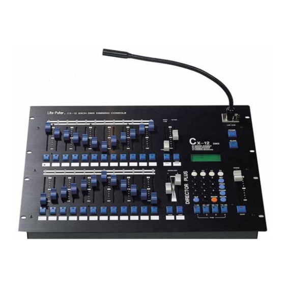
- Page 1 DIGITAL DMX PROGRAMMABLE DIMMING CONSOLE DIRECTOR PLUS CX-12 USER MANUAL VERSION 2.02...
-
Page 2: Table Of Contents
CX-12 DIRECTOR PLUS CONTENT BRIEF OPERATION DESCRIPTION STARTING CHANNEL OPERATION…………………………………1 CREATING A SCENE................3 OPERATING A SCENE ................. 4 SETTIING UP A SEQUENCE............... 5 OPERATING CHASE................6 A/B CROSS FADERS ................7 MAIN FUNCTIONS ....................8 SETUP OPERATION (FLOW CHART)............9 SEQUENCE OPERATION (FLOW CHART)........... -
Page 3: Starting Channel Operation
B. TURNING POWER ON; Hardware ac on / off switch on rear panel software; on/off switch on upper right corner of front panel C. BLANK KEY; check led light on blank key. Cx-12 is operational when when light is off. D. CHANNEL OPERATION 1. - Page 4 CX-12 DIRECTOR PLUS Example: How to set the level of the following channels; Ch#25------70% Ch#26------50% Ch#01------100% (fl) Ch#95------90% Steps : 1. Press page 2 (ch25~48) ------>LCD:PAGE START CH25 2. Adjust fader VR #1 to 70% (LCD shows channel level) 3. Adjust fader VR #2to 50% (LCD shows channel level) 4.
-
Page 5: Creating A Scene
CX-12 DIRECTOR PLUS OPERATING DESCRIPTION....Creating a scene A A scene can only be created through the set of channels. See channel operation, or the following example. B. Set the level of channels desired. C. Save channels to a scene No. - Page 6 CX-12 DIRECTOR PLUS OPERATING DESCRIPTION...... Operating a scene Scene can be recalled by: a. Using keys to load scene # b. Using fader vr to load scene # A. USING KEYS TO LOAD SCENE # First adjust all faderVR to 0% 1.
-
Page 7: A/B Cross Faders
CX-12 DIRECTOR PLUS OPERATING DESCRIPTION..Setting up a sequence Setting a sequence provides the operation for both the chaser and the A/B crossfaders. A A sequence can be made only when more than two scenes have been set. B. Prog--------------->Scene å ---->Sequence ---------------->Chaser program (for chaser) å... - Page 8 CX-12 DIRECTOR PLUS OPERATING DESCRIPTION.....Operating chase Recall a sequence program to operate chase A. Press CHASER key-------->LCD shows: SELECT:F01..F24 B. Use No. keys (01~24), to select sequence program. C. Press ENTER D. Adjust CHASER fader VR to desired level. E. Adjust SPEED fader VR to the desired level.
- Page 9 CX-12 DIRECTOR PLUS OPERATING DESCRIPTION....A/B cross faders Each cross fader, A and B, can be operated independently. Each cross fader can operate up to 24 sequences, each with a Total of 64 steps. (The sequence programs can be loaded by pressing fader VR keys’ #1~24 or keying in the number with the No.
-
Page 10: Main Functions
1. Adjust the cross faders VR to the lowest position. 2. Press cross fader VR key(s) Output value is at 0%, and operation is at the beginning of the next step. CX-12 DIRECTOR PLUS MAIN FUNCTIONS l 96 CONTROL CHANNELS / 512 PATCH OUTPUT... -
Page 11: Setup Operation (Flow Chart)
X-12 DIRECTOR PLUS SETUP OPERATION FLOW CHART NOTE: PRESS “SETUP” KEY TO RETURN TO PREVIOUS PAGE SETUP KEY 1:set up 1:lcd 1:back1 Turns on / off lcd backlight 2:concen Sets lcd concentration 2:timer 4:test for servicing 2:xio (Memory extension) 1:read Reads data from external memory 2:save Writes data to external memory... - Page 12 CX-12 DIRECTOR PLUS PROGRAMMING OPERATION FLOW CHART NOTE: PRESS “PROGRAM” KEY TO RETURN TO PREVIOUS DISPLAY PROGRAM KEY 1:scene part 1 1:load select f01..f96 Load scene to load scene 01 channel buffer for modifying. enter 2:save select f01..f96 Store channel buffer to...
- Page 13 2:program See following page for continuation of programming flow chart CX-12 DIRECTOR PLUS 2:program 1:load select f01..f24 Load program to load program 01 buffer for modifying enter 2:save Calls up last saved program select f01..f24 store buffer data to save program 01...
- Page 14 CX-12 DIRECTOR PLUS...
- Page 15 FRONT / REAR PANEL DESCRIPTION CX-12 DIRECTOR PLUS FRONT / REAR PANEL DESCRIPTION [1] FADER VR #1~24 [2] FADER VR #1~24 KEYS (2 Functions) A) Flash: individual channel (in Channel mode) B) Program select (in prog mode) / Scene select (in scene mode)
- Page 16 [21] KEY NUMBERS: 0 ~9 [22] CLEAR KEY [23] EPROM door Open only to install updated EPROM chip...
- Page 17 CX-12 DIRECTOR PLUS [24] MAIN POWER SWITCH [25] POWER FUSE (.5A) [26] AC INPUT Accepts automatically 100~240V 60/50 Hz [27] LAMP POWER SWITCH [28] DMX 512 INPUT [29] DMX 512 OUTPUT [30] ANALOG OUTPUT; 1~10V DC (1~24 CH) [31] EXTENDED MEMORY INPUT...
-
Page 18: System Configuration
CX-12 DIRECTOR PLUS SYSTEM CONFIGURATION... -
Page 19: Specification
CX-12 DIRECTOR PLUS SPECIFICATIONS POWER SUPPLY............100~240V / 50~60Hz / 0.5A ANALOG OUTPUT VOLTAGE..............0~10V DC ANALOG OUTPUT CHANNELS...............24 CH PIN 1~24: CH1~24 / PIN 25: GND ANALOG CONNECTOR..................DB25 DMX OUTPUT/INPUT........... DMX 512 / 1990 protocol DMX OUTPUT CHANNELS................. 512 DMX CONNECTORS.. - Page 20 DOCUMENT: CX-12.DOC. 07/98...
Need help?
Do you have a question about the CX-12 and is the answer not in the manual?
Questions and answers