
Related Manuals for Citronic RU105


Summary of Contents for Citronic RU105
- Page 1 RU105 Multi-UHF Wireless System Item ref: 171.972UK, 171.973UK User Manual Version 1.0 Caution: Please read this manual carefully before operating Damage caused by misuse is not covered by the warranty...
- Page 2 Introduction Thank you for choosing the Citronic RU105 wireless system. This professional wireless set provides a high quality microphone with a PLL tuned UHF radio system for freedom of movement without loss of audio quality. Please read this manual before using this equipment in order to avoid damage through incorrect operation and to get the best performance from your purchase.
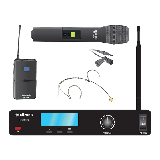
- Page 3 Receiver IR sync sender LCD display Previous (Group/Channel setting) Next (Group/Channel setting) Set (Group/Channel) Output volume control Power on/off switch Balanced XLRM output Unbalanced 6.3mm jack output 10. DC power in jack (5.5 x 2.1mm) 11. Antenna connector (BNC) Transmitter 12.
- Page 4 If the receiver is to be rack-mounted, place the supplied rack ears against each side of the receiver and fix securely with 2 screws in each. These rack ears have a hole for front-mounting the antenna and a BNC extension lead for fixing into the hole. This should be connected to the BNC on the rear panel, creating a front socket for the antenna to connect onto.
- Page 5 In Use Switching on the transmitter will open up the radio carrier frequency to the receiver and also send a pilot tone frequency, which is not audible but is used by the receiver to open the audio channel. This system helps to avoid any spurious radio frequencies interfering with the wireless microphone signal. When the transmitter’s RF signal is recognized by the receiver, an RF meter will show the carrier signal strength in the LCD display.
-
Page 6: Specifications
RF or AF signals Check that the transmitter batteries are good / charged showing Ensure that a genuine Citronic RU series transmitter is being used Ensure transmitter and receiver frequencies are synced (see “Tuning”) Check that transmitter switch is not in “MUTE” position...
Need help?
Do you have a question about the RU105 and is the answer not in the manual?
Questions and answers