Table of Contents
Advertisement
Advertisement
Table of Contents

Related Manuals for Mastech MS8221C


Summary of Contents for Mastech MS8221C
- Page 1 DIGITAL MULTIMETER INSTRUCTION MANUAL...
-
Page 2: Table Of Contents
DIGITAL MULTIMETER CONTENTS CONTENTS SAFETY INFORMATION ……1 PRELIMINARY ……1 DURING USE ……2 SYMBOLS ……3 MAINTENANCE ……4 DESCRIPTION ……5 NAMES OF COMPONENTS ……5 SWITCH, BUTTONS AND INPUT JACK ……6 ELUCIDATION SPECIFICATIONS ……7 GENERAL SPECIFICATIONS ……7 ELECTRICAL SPECIFICATIONS ……8 OPERATING INSTRUCTION ……13 POWER-UP ……13 DATA HOLD... - Page 3 DIGITAL MULTIMETER CONTENTS 4.14 CURRENT MEASURING (WITH ……22 CLAMP, OPTIONAL) 4.15 MEASURING RESISTANCE ……23 4.16 MEASURING TEMPERATURE ……24 4.17 MEASURING CAPACITANCE ……25 4.18 DIODE TESTING ……26 4.19 CONTINUITY TESTING ……27 4.20 TRANSISTOR TESTING ……28 MAINTENANCE ……29 BATTERY REPLACEMENT ……29 FUSE REPLACEMENT ……29 TEST LEADS REPLACEMENT ……30...
-
Page 4: Safety Information
DIGITAL MULTIMETER SAFETY INFORMATION SAFETY INFORMATION WARNING To ensure safe operation, and in order to exploit to the full the functionality of the meter, please follow the directions in this section carefully. This multimeter been designed according IEC-61010-1 concerning electronic measuring instruments with an overvoltage category CAT ΙΙΙ... -
Page 5: During Use
DIGITAL MULTIMETER SAFETY INFORMATION or same electric ratings. 1.2 DURING USE 1.2.1 Before using, you must select the right input jack, function and range. 1.2.2 Never exceed the protection limit values indicated in specifications for each range of measurement. 1.2.3 When the meter is linked to a measurement circuit, do not touch unused terminals. -
Page 6: Symbols
DIGITAL MULTIMETER SAFETY INFORMATION 1.2.11 If any faults or abnormalities are observed, the meter can not be used any more and it has to be checked out. 1.2.12 Never use the meter unless the rear case is in place and fastened fully. 1.2.13 Please do not store or use meter in areas exposed to direct sunlight,... -
Page 7: Maintenance
DIGITAL MULTIMETER SAFETY INFORMATION DATA-H This indicates that the display data is being held. AUTO Auto range The battery is not sufficient for proper operation. 1.4 MAINTENANCE 1.4.1 Please do not attempt to adjust or repair the meter by removing the rear case while voltage is being applied. A technician who fully understands danger involved should only carry out such actions. -
Page 8: Description
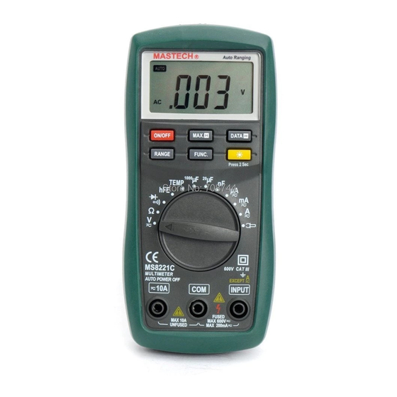
DIGITAL MULTIMETER DESCRIPTION 2. DESCRIPTION - This meter is a portable professional measuring instrument with handsome LCD and back light easily reading. Single operation transform switch makes measurement convenient. Overload protection and low battery indication are provided, this meter is ideal for use in the fields, workshop, school, hobby and home applications. -
Page 9: Switch, Buttons And Input Jack
DIGITAL MULTIMETER DESCRIPTION 2.2 SWITCH, BUTTONS AND INPUT JACK ELUCIDATION • ON/OFF Button This Button is used to the switch of power. • RANGE Button This button is used to transform Auto range or manual range. • FUNC. Button This button is used to transform function. •... -
Page 10: Specifications
DIGITAL MULTIMETER SPECIFICATIONS 3. SPECIFICATIONS Accuracy is specified for a period of year after calibration and at 18℃ to 28℃ (64°F to 82°F) with relative humidity to 75%. 3.1 GENERAL SPECIFICATIONS 3.1.1 Auto ranges and manual range. 3.1.2 Max. Voltage Between Terminals And Earth Ground: 600V DC or AC 3.1.3 Fuse Protection: F 200mA/250V (quick acting). -
Page 11: Electrical Specifications
DIGITAL MULTIMETER SPECIFICATIONS 3.2 ELECTRICAL SPECIFICATIONS Circumstance Temperature: 23±5℃ Relative Humidity: < 75% 3.2.1 DC Voltage Range Resolution Accuracy 200mV 0.1mV 0.001V ±(0.7% of rdg + 2 digits) 0.01V 200V 0.1V 600V - Input Impedance: 10MΩ - Overload Protection: 200mV range: 250V DC or AC rms, 2V-600V ranges: 600V DC or AC rms. - Page 12 DIGITAL MULTIMETER SPECIFICATIONS 3.2.3 DC Current Range Resolution Accuracy 200μA 0.1μA ±(1.2% of rdg + 3 digits) 2000μA 1μA 20.00mA 0.01mA 200.0mA 0.1mA ±(2.0% of rdg + 10 digits) 2.000A 0.001A 10.00A 0.01A - Overload Protection: μA, mA ranges: F 200mA/250V fuse (quick acting), 2A, 10A range: unfused.
- Page 13 DIGITAL MULTIMETER SPECIFICATIONS - Voltage Drop:200µA、20mA、2A: 20mV, 2000µA、200mA、10A range: 200mV 3.2.5 DC Current (with clamp, optional) Range Resolution Accuracy ± (1.2 % of rdg + 3 digits) meter 0.1mV/0.1A 200A Typical ±(2.0 %) DC Clamp 0.1A /0.1mV 0 to 200A ±...
- Page 14 DIGITAL MULTIMETER SPECIFICATIONS - Open circuit voltage: approx. 0.5V - Overload Protection: 250V DC or AC rms 3.2.8 Resistance Range Resolution Accuracy ±(1.0% of rdg + 3 digits) 200Ω 0.1Ω 2kΩ 0.001kΩ ±(1.0% of rdg + 1 digit) 20kΩ 0.01kΩ 200kΩ...
- Page 15 DIGITAL MULTIMETER SPECIFICATIONS 3.2.10 Capacitance Range Resolution Accuracy ±(4.0% of rdg +10digits) 20nF 0.01nF 200nF 0.1nF 2µF 0.001µF ±(4.0% of rdg + 3 digits) 20µF 0.01µF 200µF 0.1µF 1000µF 1µF - Overload Protection: 20nF~20µF ranges: F 200mA/250V fuse (quick acting). 200µF/1000µF ranges: No Overload Protection.
-
Page 16: Operating Instruction
DIGITAL MULTIMETER OPERATING INSTRUCTION 4. OPERATING INSTRUCTION 4.1 POWER-UP Press the ‘ON/OFF’ button to turn the meter ON or OFF. 4.2 DATA HOLD If you need data hold when measuring, you can put on ‘DATA-H’ button, it will hold the reading; if you put the button again, data hold is not continue. -
Page 17: Back Light
DIGITAL MULTIMETER OPERATING INSTRUCTION 4.6 BACK LIGHT If the light is dark to make the reading difficult when measuring, you can press ‘ ‘ button to turn on the back light, which will last for 15 seconds. Continuous pressing the button for two seconds will turn off the back light. -
Page 18: Preparation For Measurement
DIGITAL MULTIMETER OPERATING INSTRUCTION will recover the working condition. If presses the ‘FUNC.’ when power is on, auto power off disable. 4.8 PREPARATION FOR MEASUREMENT 4.8.1 Put on the ‘ON/OFF’ button. If the battery voltage is less than 3.8V, display will show ‘ ’, the battery should be changed at this time. - Page 19 DIGITAL MULTIMETER OPERATING INSTRUCTION 4.9.1 Connect the black test lead to the COM jack and the red test lead to the INPUT jack. 4.9.2 Set the transform switch at the V range position. 4.9.3 Put down the ‘FUNC.’ to enter measurement.
-
Page 20: Measuring Ac Voltage
DIGITAL MULTIMETER OPERATING INSTRUCTION 4.10 MEASURING AC VOLTAGE WARNING You can’t input the voltage which more than 600V rms AC, it’s possible to show higher voltage, but it’s may destroy the inner circuit. Pay attention not to get an electric shock when measuring voltage. -
Page 21: Measuring Dc Current
DIGITAL MULTIMETER OPERATING INSTRUCTION • At the manual range mode, when the value scale to be measured is unknown beforehand, set the range selector at the highest position. 4.11 MEASURING DC CURRENT WARNING Shut down the power of the tested circuit, then connect the meter with the circuit for measurement. -
Page 22: Dc Current Measuring
DIGITAL MULTIMETER OPERATING INSTRUCTION 4.11.5 You can get reading from LCD. The polarity of red test lead will be indicated. NOTE: • When only the figure ‘OL’ is displayed, it indicates overrange situation and the higher range has to be selected. -
Page 23: Clamp, Optional) Measuring Ac Current
DIGITAL MULTIMETER OPERATING INSTRUCTION the 10A jack. 4.12.2 Set the transform switch at the desired μA mA or A range position. 4.12.3 Put down the ‘FUNC.’ to enter the AC measurement. Auto range or manual range can be transformed by putting the ‘RANGE’. - Page 24 DIGITAL MULTIMETER OPERATING INSTRUCTION can be transformed by putting the ‘RANGE’. 4.13.4 Clamp the circuit under measured. 4.13.5 You can get reading from LCD. The polarity of red output lead will be indicated. NOTE: • Select the DC clamp to measure the DC current. •...
-
Page 25: Ac Current Measuring
DIGITAL MULTIMETER OPERATING INSTRUCTION 4.14 AC CURRENT MEASURING (WITH CLAMP, OPTIONAL) 4.14.1 Connect the black output lead of clamp to the COM jack and the red one to the INPUT jack of the meter. 4.14.2 Set the transform switch range position. 4.14.3 Put down the ‘FUNC.’... -
Page 26: Measuring Resistance
DIGITAL MULTIMETER OPERATING INSTRUCTION measured value. b. If the sensitivity of the selected clamp is low (0.1A/0.01mV), the indicated value will be 10 times lower than the measured value. For example, the measured current is 100A, then the indicated value will be 10.0A. -
Page 27: Measuring Temperature
DIGITAL MULTIMETER OPERATING INSTRUCTION 4.15.4 You can get reading from LCD. NOTE: • At the manual range mode, when only the figure ‘OL’ is displayed, it indicates overrange situation and the higher range has to be selected. • For measuring resistance above 1MΩ, the meter may take a few seconds to get stable reading. -
Page 28: Measuring Capacitance
DIGITAL MULTIMETER OPERATING INSTRUCTION for measurement. 4.16.5 You can get reading from LCD. NOTE: • With better hermetization, the meter’s temperature measured circuit and environment need a little longer time to reach heat balance, and then accurate reading can be gotten. 4.17 MEASURING CAPACITANCE WARNING To avoid electric shock, be sure the capacitors have... - Page 29 DIGITAL MULTIMETER OPERATING INSTRUCTION discharged fully. 4.17.5 You can get reading from LCD. 4.17.6 When frequent capacitor testing is needed, put the plug of multifunction test socket into COM and INPUT and put the capacitor foot into two long socket of capacitor testing equipment, capacitor testing is ready.
- Page 30 DIGITAL MULTIMETER OPERATING INSTRUCTION • If the lead connection is reversed, only figure ‘OL’ will be displayed. • When the input is not connected, i.e. at open circuit, the figure ‘OL’ will be displayed. 4.19 TESTING CONTINUITY WARNING When testing the circuit continuity, be sure that the power of the circuit has been shut down and all capacitors have been discharged fully.
- Page 31 DIGITAL MULTIMETER OPERATING INSTRUCTION 4.20 TESTING TRANSISTOR 4.20.1 Set the transform switch at the hFE range position. 4.20.2 Put two plugs ’-‘ and ‘+’ of multifunction test socket into COM jack and INPUT jack respectively. 4.20.3 Identify whether transistor is NPN or PNP type and insert emitter, base and collector leads into the proper holes of the transistor...
-
Page 32: Maintenance
DIGITAL MULTIMETER MAINTENANCE 5. MAINTENANCE 5.1 BATTERY REPLACEMENT WARNING Before attempting open the battery cover of the meter, be sure that test leads have been disconnected from measurement circuit to avoid electric shock hazard. 5.1.1 If the sign ‘ ’ appears on the LCD display, it indicates that the battery should be replaced. -
Page 33: Test Leads Replacement
DIGITAL MULTIMETER MAINTENANCE 5.3 TEST LEADS REPLACEMENT WARNING Full in compliance with safety standards can be guaranteed only if used with test leads supplied. If necessary, they must be replaced with the same model or same electric ratings. Electric ratings of the test leads: 600V 10A. -
Page 34: Accessories
DIGITAL MULTIMETER ACCESSORIES 6. ACCESSORIES Test Leads: Electric Ratings 600V 10A one piece ⑴ Battery:1.5V, AAA three pieces ⑵ Operating Manual one piece ⑶ Thermocouple (K type) one piece ⑷ Multifunction test socket one piece ⑸ - 31 -...
Need help?
Do you have a question about the MS8221C and is the answer not in the manual?
Questions and answers