Table of Contents
Advertisement
Available languages
Available languages
Use & Care Guide
Manual de Uso y Cuidado
English / Español
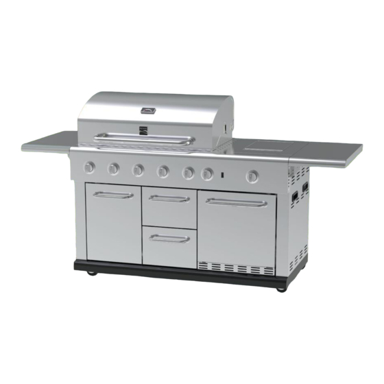
Kenmore
Island Grill with Refrigerator
Parrilla tipo isla con frigorí fico
Models/Modelos: 139.20153510
Items / Artí culos: 640-08678222-4
P/N 3108226-Manual Rev 1 01/12
Sears Brands Management Corporation
Hoffman Estates, IL 60179 U.S.A.
www.kenmore.com
www.sears.com
www.kmart.com
®
®
1
Advertisement
Table of Contents

Related Manuals for Kenmore 139.20153510


Summary of Contents for Kenmore 139.20153510
- Page 1 Manual de Uso y Cuidado English / Español Kenmore ® Island Grill with Refrigerator Parrilla tipo isla con frigorí fico Models/Modelos: 139.20153510 Items / Artí culos: 640-08678222-4 P/N 3108226-Manual Rev 1 01/12 Sears Brands Management Corporation Hoffman Estates, IL 60179 U.S.A. www.kenmore.com www.sears.com...
-
Page 2: Grill Service Center
Installation Safety Precautions • Use grill, as purchased, only with LP (propane) gas and the regulator/valve assembly supplied. A conversion kit must be purchased for use with natural gas. If you smell gas: • Grill installation must conform with local codes, or in their absence of local codes, with either the National Fuel Gas 1. -
Page 3: Table Of Contents
Installation Safety Precautions ......2 defective appliance will receive free repair or replacement at Kenmore Grill Warranty ..... . . …3-4 option of seller. -
Page 4: For Your Safety
LP Cylinder Disclaimer of implied warranties; limitation of remedies • The LP cylinder used with your grill must meet the Customer’s sole and exclusive remedy under this limited warranty following requirements: shall be product repair or replacement as provided herein. Implied •... - Page 5 LP Tank Exchange Connecting Regulator To The LP Tank •Many retailers that sell grills offer you the option of replacing 1. LP tank must be properly secured onto grill. (Refer to your empty LP tank through an exchange service. Use only assembly section.) those reputable exchange companies that inspect, precision 2.
- Page 6 Leak Testing Valves, Hose and Regulator 1. Turn all grill control knobs to OFF. 2. Be sure regulator is tightly connected to LP tank. 3. Completely open LP tank valve by turning OPD hand wheel counterclockwise. If you hear a rushing sound, turn gas off Hold coupling nut and regulator immediately.
- Page 7 Safety Tips Before opening LP cylinder valve, check the coupling nut for tightness. When grill is not in use, turn off all control knobs and LP For Safe Use of Your Grill and to Avoid Serious cylinder valve. Injury: Never move grill while in operation or still hot. •...
-
Page 8: Use And Care
4. If ignition does not occur in 5 seconds, turn the burner control off, wait 5 minutes for gas to clear away, and repeat step 3. 5. To light other burners, repeat step 3. NOTE: If ignitor does not work, follow Match Lighting instructions. -
Page 9: Spider Alert
Drawer Removal and Replacement Do not use citrisol, abrasive cleaners, degreasers or a Remove the two center drawers to clean grill interior surfaces as concentrated grill cleaner on plastic parts. Damage to and described in the procedure below. failure of parts can result. CAUTION: Be extremely careful of hand and finger placement •Porcelain surfaces: Because of glass-like composition, most when removing or replacing drawers. - Page 10 We suggest three ways to clean the burner tubes. Use the one easiest for you. (A) Bend a stiff wire (a light weight coat hanger works well) into a small hook. Run the hook through each burner tube several times. 2 Burner Cooking Great indirect cooking on low.
- Page 11 Gas Requirements Care and Maintenance Time Table Chart LP Gas Frequency Based If your grill is for LP Gas, the regulator supplied is set for Grill Item on Normal Use Cleaning Method an 11-in. water column (WC) and is for use with LP gas only.
-
Page 12: Natural Gas Conversion Kit
Natural gas conversion kit 2. Insert plug and release sleeve. Kenmore Model # 20152 (Manufacturer Part No.: 9143028) 3. Push plug until sleeve snaps forward. (Gas will flow automatically. Failure to connect plug properly to socket will inhibit gas flow to the appliance.) - Page 13 Part list detail with graphic: Description Artwork Side Burner Drip Tray Side Table Left Bracket Assembly Side Table Right Bracket Assembly Left Side Shelf Panel Assembly Right Side Shelf Panel Assembly Knob Heat Diffusers Main burner Cooking Grid Warming Rack...
- Page 14 Drip Cup Side Burner Cooking Grid Hardware Tool Kit Hardware Tool Kit: AA. AA Battery BB. M6*12 Screw CC. M6 Nut DD. M6 Stretch EE. M6 Shoulder QTY: 1 pcs QTY: 8 pcs QTY: 4 pcs Washer Screw QTY: 4 pcs QTY: 4 pcs If you are missing hardware or have damaged parts after unpacking grill, call 1-800-482-0131 for replacement.
- Page 15 : Parts List Description Part. No. Description Part. No. Warming Rack 2408460 Knob 2404108 Main Burner Assembly CH255001 Switch 2404129 Hood Assembly CH255002 Rotisserie Burner Ignition 2408461 Wire Hood Body CH255003 Side Burner Ignition Wire 2408466 Hood Handle 2404015 450mm Main Burner 2408464 Ignition Wire 450mm Bezel-Handle...
-
Page 16: Use And Care
Assembly Battery 2307756 77.4 Refrigerator Handle CH255012 Assembly Side Shelf Left Bracket 5205579 Handle Bezel 5201175 Left Side Shelf Panel 5205577 Door Screw Cap 2100481 Assembly Side Shelf Right Bracket 5205580 Drawer Handle Assembly 5201886 Side Burner Ripple Tube 2307241 Drawer Assembly Side Burner Nozzle 5205893... - Page 17 Part Diagram:...
-
Page 18: Assembly
ASSEMBLY INSTRUCTIONS IMPORTANT: Assemble the grill on a flat level surface. During assembly, check the parts and hardware for correct identification against the list and diagrams on pages 13–14 of this Use & Care Guide. 1.Side Burner Drip Tray Insert side burner drip tray into position at rear of side burner as shown. - Page 19 2.Side shelf brackets Install the 4 side shelf brackets with 2 (BB)M6x12 screws each as shown. 3.Side shelf attachment Attach right side shelf onto brackets as shown with 2 (CC) M6 nuts, 2 (DD) M6 Stretch Washers and 2 (EE) M6 screws.
- Page 20 4.Control knobs, heat diffusers, cooking grids, warming rack As shown below, attach the 7 control knobs and insert the 5 heat diffusers, 4 cooking grids and the warming rack.
- Page 21 5. Insert the side burner cooking grid as shown. 6.Open the left door and remove the battery compartment cap. Insert an AA battery into the compartment and reassemble the cap.
- Page 22 7.Drip cup Open the left door and insert the drip cup into its bracket as shown. 8.LP gas tank - Loosen the tank retention screw. - Place the LP gas tank, collar opening facing forward, into the tank location hole in the grill base. - Connect the regulator to the LP tank valve.
- Page 23 TROUBLESHOOTING FOR GRILL Problem Possible Cause Corrective Action 1. The ignition wire came off the 1. Reconnect the ignition wire to the electrical electrical igniter. igniter. 2. The distance between the ignition pin and the burner is greater than 2. Loosen the ignition pin and adjust the 0.1-0.2 inch(side burner).
- Page 24 Problem Possible Cause Corrective Action 1. Refill the LP Tank. 1. LP tank is empty. 2. Install the burner correctly. Burner blows out 2. Burner is not aligned with the control valve. 3. Check the gas supply hose and make sure 3.
-
Page 25: Assembly
Problem Possible Cause Corrective Action The propane regulator assembly Please follow these instructions: 1. Make sure incorporates an excess flow device all burners are “OFF”. 2. Open the tank designed to supply the grill with valve and wait 5 minutes. 3. Light the burner Low heat, LP gas sufficient gas flow. - Page 26 REFRIGERATOR SAFETY INFORMATION To reduce the electrical shock or injury when using the refrigerator, follow basic precautions including the following: WARNING • Plug into a grounded 3-prong GFI outlet. Do not remove grounding prong, do not use an adaptor. Because of potential safety hazards under certain conditions, it is strongly recommended that you do not use an extension cord with this appliance.
- Page 27 INSTRUCTIONS Before Using Your Unit • Your grill has a built-in refrigerator as shown in the illustration below. Clean the refrigerator interior surfaces with a soft cloth moistened in lukewarm water. Plugging for refrigerator • Plug the unit into an exclusive, properly installed-grounded GFI wall outlet. Do not under any circumstances cut or remove the third (ground) prong from the power cord.
-
Page 28: Care And Maintenance
CARE AND MAINTENANCE Cleaning Your Unit Turn the temperature control to "0," unplug the unit, and remove the food and shelf. • Clean the water with dry cloth when the frost turns into water. • Wash the inside surfaces with a warm water and baking soda solution. The solution should be about 2 tablespoons of baking soda to one quart of water. -
Page 29: Troubleshooting For Refrigerator
TROUBLESHOOTING FOR REFRIGERATOR Problem Possible Cause Corrective Action Unit does not Not plugged in. 1. Firmly plug the cord into a live outlet with operate. proper voltage. 2. The circuit breaker tripped or a blown fuse. 2. Reset the circuit breaker or replace the fuse. 3. -
Page 30: Technical Data And Wiring Diagram
TECHNICAL DATA AND WIRING DIAGRAM Technical Data: Model R-60 Rated Voltage (V) AC110 Rated Frequency (Hz) Rated Input Power (W) 110W Energy Consumption (Kw.h /24h) 0.70 Rated Current (A) 1.45 Phase Design Pressure (High) (Psig) Design Pressure (Low) (Psig) Refrigerant R134a Refrigerant Charge (Pounds) 0.07... - Page 31 Medidas de seguridad en la instalación PELIGRO Use la parrilla tal y como la compró, solo con gas LP (Propano) y la válvula que viene con el producto. Se debe comprar un kit de conversión para el uso con gas natural. Si huele a gas: If you smell gas: La instalación de la parrilla de hacerse de acuerdo con las...
-
Page 32: Parts List And Parts Diagram
Montaje................47-51 Kenmore Grill Warranty ......3 DURANTE DIEZ AÑOS a partir de la fecha de compra, si Problemas Soluciones de la Parrilla......52-54... - Page 33 Botella LP Descargo de responsabilidad de garantí as implí citas, limitación de La botella LP usada en su parrilla debe de cumplir los responsabilidades. Es responsabilidad exclusiva del cliente bajo esta garantí a limitada siguientes requisitos. de la reparación del producto tal y como se provee. Cualesquiera Use botellas LP con las medidas requeridas 12"...
- Page 34 Cambio de botella LP Conectar el regulador al tanque LP Connecting Regulator To The LP Tank Muchos vendedores que venden parrillas le ofrecen la 1.El tanque LP debe de estar asegurado a la parrilla. (Vaya 1. LP tank must be properly secured onto grill. (Refer to opción de rellenar su botella mediante un cambio.
- Page 35 Comprobar fugas en las válvulas, manguera y regulador Leak Testing Valves, Hose and Regulator 3) Ponga los pulsadores en OFF. 4) Asegúrese de que el regulador está bien conectado al 1. Turn all grill control knobs to OFF. tanque LP. 5) Abra la válvula del tanque completamente girando la 2.
- Page 36 Consejos de Seguridad Safety Tips ▲ Antes de abrir la válvula de la botella LP, compruebe que ATENCIÓ N Before opening LP cylinder valve, check the coupling nut la rosca está bien apretada. for tightness. ▲ Cuando no use la parrilla, cierre todos los pulsadores y la When grill is not in use, turn off all control knobs and LP válvula de la botella LP.
- Page 37 4.Si no se enciende en 5 segundos, apague el quemador, espere 5 minutos para que se vaya el gas acumulado y 4. If ignition does not occur in 5 seconds, turn the burner repita el paso 3. control off, wait 5 minutes for gas to clear away, and repeat 5.Para encender otros quemadores repita el paso 3.
- Page 38 Extracción y colocación del cajón No use citrisol, limpiadores abrasivos, desengrasantes o un Retire los dos cajones centrales para limpiar las superficies del limpiador de parrillas concentrado en partes de plástico. Puede interior de la parrilla tal y como se describe en el siguiente dañar las partes.
- Page 39 Sugerimos tres modos de limpiar los tubos quemadores. Use el que más le convenga. A) Doble un alambre duro (una percha ligera por ejemplo) y haga un gancho. Frote el gancho en cada quemador varias veces. Cocinar con 2 quemadores Muy buena cocción indirecta.
- Page 40 Tiempo de cuidado y mantenimiento Requisitos de Gas Gas Requirements Care and Maintenance Time Table Chart Gas LP LP Gas Frecuencia Si su parrilla es para gas LP, el regulador viene Frequency Based If your grill is for LP Gas, the regulator supplied is set for Objeto en uso Método de limpieza...
- Page 41 Natural gas conversion kit 2. Inserte el conector y suelte la manga. 2. Insert plug and release sleeve. Kenmore Model # 20152 3. Empuje el conector hasta que la manga se (Manufacturer Part No.:) empuje hacia delante. (El gas fluirá...
- Page 42 Lista Detallada de Partes con Dibujo: Nº . Cantidad Descripción Dibujo Bandeja anti-goteo para el quemador lateral Conjunto del soporte de la mesa lateral izquierda Conjunto del soporte de la mesa lateral derecha Conjunto del panel de la balda lateral izquierda Conjunto del panel de la balda lateral derecha Mando...
- Page 43 Recipiente de goteo Parrilla del quemador lateral Kit de herramientas Kit de herramientas: AA. AA Pila BB. M6*12 Tornillo CC. M6 Tuerca DD. M6 Arandela EE. M6 Tornillo de QTY: 1 pcs QTY: 8 pcs QTY: 4 pcs elástica resalto QTY: 4 pcs QTY: 4 pcs Si faltan piezas o ha dañado algunas después de desembalar la parrilla, llame al 1-800-482-0131 para su...
- Page 44 Descripción de las partes: Descripción Part. No. Descripción Part. No. Rejilla calentadora 2408460 Mando 2404108 Conjunto del quemador CH255001 Interruptor 2404129 principal Conjunto de la campana CH255002 Cable de ignición del 2408461 quemador del asador Cuerpo de la campana CH255003 Cable de ignición del 2408466 quemador lateral...
- Page 45 lámina Cable 600 mm 2307751 Conjunto del panel fijo del 5205575 inyector del quemador lateral Pasador del quemador 2300819 Conjunto del panel interior 5205588 lateral derecho del carro Cubierta del quemador 5205573 Escudo de calor de la 5205566 lateral balda lateral Parrilla del quemador 2408468 Inserción del asa...
- Page 46 Diagrama de partes:...
- Page 47 INSTRUCCIONES DE MONTAJE IMPORTANTE: Monte la parrilla en una superficie plana. Durante el montaje, compruebe que las partes y las herramientas estén tal y como en la lista y diagramas en las páginas 13–14 de esta Guí a de uso y cuidado. 1.
- Page 48 2.Soportes para la balda lateral Instale los 4 soportes para la balda lateral con 2 tornillos (BB) M6 x12 en cada uno, como se muestra. 3.Fijación de la balda lateral Fije la balda lateral derecha en los soportes como se indica, con 2 tuercas (CC) M6, 2 arandelas elásticas (DD) M6 y 2 tornillos (EE) M6.
- Page 49 4.Mandos de control, difusores de calor, parrillas, rejilla calentadora Como se indica a continuación, fije los 7 mandos de control e inserte los 5 difusores de calor, las 4 parrillas y la rejilla calentadora.
- Page 50 5.Inserte la parrilla del quemador lateral como se indica. 6.Abra la puerta izquierda y retire la tapa del compartimento de la pila. Inserte una pila AA en el compartimento y vuelva a colocar la tapa.
- Page 51 7.Recipiente de goteo Abra la puerta izquierda e inserte el recipiente de goteo en su soporte como se indica. 8.Tanque de gas LP - Afloje el tornillo de retención del tanque. - Coloque el tanque de gas LP, con la abertura del cuello orientada hacia delante, en el orificio de colocación del tanque de la base de la parrilla.
- Page 52 SOLUCIÓ N DE PROBLEMAS Problema Posible Causa Solución 1. El cable de ignición se salió 1.Reconecte cable ignición del encendedor. encendedor eléctrico. distancia entre pasador de ignición y el 2.Afloje el pasador de ignición y ajuste la quemador es mayor de 0.1 o distancia, vuelva a apretar.
- Page 53 Problema Posible Causa Solución 1.Rellene la botella 1. La botella está vací a 2.Instale correctamente el quemador 2. El quemador no está alineado con El quemador tira aire la válvula de control. 3.Compruebe la manguera de suministro de gas y asegúrese de que no hay fugas o 3.
- Page 54 Problema Posible Causa Solución El regulador de propano de la Por favor siga las instrucciones: 1. Asegúrese parrilla tiene un dispositivo de de que todos los quemadores están en OFF. exceso de flujo para dar el flujo 2. Abra la válvula de la botella y espere 5 Poco calor, gas LP correcto.
- Page 55 REFRIGERATOR SAFETY INFORMATION Para reducir el riesgo de descarga eléctrica o lesiones al usar el refrigerador, tome precauciones básicas, incluidas las siguientes: ADVERTENCIA • Enchufe el cable en un tomacorriente de 3 clavijas de circuito de falla conectado a tierra. No retire la clavija conectada a tierra, ni use un adaptador.
- Page 56 INSTRUCCIONES Antes de usar la unidad • Su parrilla incorpora un refrigerador como se muestra en la siguiente ilustración. Limpie la superficie interior del refrigerador con un paño suave humedecido con agua tibia. Conectar el refrigerador • Enchufe la unidad en un tomacorriente de pared con interruptor de circuito por falla a tierra exclusivo y con la debida conexión a tierra.
-
Page 57: Cuidado Y Mantenimiento
CUIDADO Y MANTENIMIENTO Limpieza de la unidad • Gire el control de temperatura a la posición “OFF” (APAGADO), desenchufe la unidad y retire los alimentos y el estante. Seque el agua con un paño seco cuando la escarcha se derrita. •... - Page 58 TROUBLESHOOTING FOR REFRIGERATOR Problema Posible Causa Solución La unidad no 1. No está enchufada. 1. Enchufe firmemente el cable en un funciona. 2. Se fundió un fusible o el interruptor tomacorriente activo con el voltaje de circuito se desconectó. adecuado. 3.
- Page 59 1.45 Fase Presión de diseño (Alta) (Psig) Presión de diseño (Baja) (Psig) Refrigerante R134a Carga de refrigerante (libras) 0.07 Modelo 139.20153510 Propano o Gas Tipo de gas Natural Presión 11”WC o 7”WC Quemador principal 50,000 BTU/HR Quemador secundario 10,000 BTU/HR...
- Page 60 Diagrama del cableado: Diagrama del cableado eléctrico Termostato Enchuf Motor del ventilador del condensador Compresor Dispositivo protector...
- Page 61 © 2012 KCD IP, LLC...
Need help?
Do you have a question about the 139.20153510 and is the answer not in the manual?
Questions and answers
What do in need to check if the refrigerator is not coming on once plugged in?
How much is this grill