
Subscribe to Our Youtube Channel
Related Manuals for Sencore DMG 3200


Summary of Contents for Sencore DMG 3200
-
Page 1: User Manual
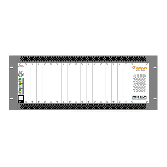
DMG 3200/3100/3000 Digital Media Gateway User Manual SWITCH IPIO Control DMG 3200 Status HI-DENSITY MODULAR HOT-SWAP DMG 3200 CONTROL DATA A DATA B December 2014 8037A www.sencore.com | 1.605.978.4600 Revision 2.0... - Page 2 Inquiries should be made directly to those companies. This document may also have links to third-party web pages that are beyond the control of Sencore. The presence of such links does not imply that Sencore endorses or recommends the content on those pages. Sencore acknowledges the use of third-party open source software and licenses in some Sencore products.
-
Page 3: Revision History
DMG 3200/3100/3000 – User Manual Revision History Date Version Description Author 01/09/12 Initial Release 12/01/14 DMG 3200 Release Page 3 (306) - Page 4 DMG 3200/3100/3000 – User Manual FCC Class A Information The DMG 3200/3100/3000 has been tested and found to comply with the limits for a Class A digital device, pursuant to Part 15 of the FCC Rules. These limits are designed to provide reasonable protection against harmful interference when the equipment is operated in a commercial environment.
- Page 5 • Always refer to the manual for safe operation. If you have a question about the application or operation call SENCORE for assistance. • Never allow your equipment to be exposed to water or high moisture environments.
-
Page 6: Package Contents
DMG 3200/3100/3000 – User Manual Package Contents The following is a list of the items that are included along with the DMG 3200/3100/3000: 1. User Manual 2. Quick Install Guide 3. AC Power Cable (2 for DMG 3200 and 3000, 1 for DMG 3100) Note: If any option cables were ordered with the DMG 3200/3100/3000, they will be included in the box as well. -
Page 7: Table Of Contents
DMG 3200/3100/3000 – User Manual Table of Contents Introduction ....................12 Installation and Safety .................. 13 Installation and Safety ...................... 13 2.1.1 The 4RU Chassis ......................13 2.1.2 1RU Chassis DMG 3200....................15 2.1.3 Safety Considerations ....................16 2.1.4 Installation ........................17 2.1.5... - Page 8 DMG 3200/3100/3000 – User Manual 4.3.3 Demo Licenses ......................44 Input Configuration ..................44 The Inputs Node ....................... 44 Input Analysis ........................45 5.2.1 Input Port Analysis ....................... 46 5.2.2 Input Service Filtering and Analysis ................47 5.2.3 Input PID Analysis ......................48 Manual PSI ........................
- Page 9 DMG 3200/3100/3000 – User Manual 7.3.6 EPG..........................134 7.3.7 Service ........................134 7.3.8 Components ....................... 137 7.3.9 Scrambling ......................... 143 Output Port Settings ....................... 145 7.4.1 IP Output module ....................... 145 7.4.2 Cloned IP Output Module ..................147 7.4.3 Dual IP Output ......................150 7.4.4...
- Page 10 DMG 3200/3100/3000 – User Manual 8.4.3 MPEG-2 Parameters ....................210 8.4.4 H.264 Parameters ...................... 210 Universal Broadcast Transcoder Configuration ............. 212 8.5.1 Source Parameters ....................214 8.5.2 Pre-Processing Parameters ..................216 8.5.3 Video Parameters ...................... 217 8.5.4 Video Extended Parameters ..................218 8.5.5...
- Page 11 DMG 3200/3100/3000 – User Manual 10.4.1 Redundancy Group Configuration ................272 10.4.2 Redundancy Module Configuration ................272 10.4.3 Manual Switching ....................... 276 10.4.4 SDI Input switch configuration ................... 276 10.5 MMI Redundancy ......................279 10.5.1 MMI Redundancy Configuration ................279 10.5.2 MMI Switching Criteria ....................
-
Page 12: Introduction
DMG 3200/3100/3000 – User Manual 1 Introduction DMG 3200/3100/3000 Thank you for purchasing the . This manual describes how to install, configure, and operate your new equipment. It is written for professional operators of video distribution systems and assumes a prerequisite level of technical knowledge. -
Page 13: Installation And Safety
Sencore products can be delivered in different chassis variations - 1RU chassis and a 4RU chassis. The product models DMG 3000 and DMG 3200 represents the 4RU chassis, while the product models DMG 3100 and DMG 3200 represents 1RU chassis. - Page 14 Broadcast mounting, air flow will be from back to front. 2.1.1.3 Replacing the power supply module The 4RU chassis can be installed with one or two power supply modules (DMG 3200 always comes with two power supply modules). The modules can be exchanged from the rear of the unit.
-
Page 15: 1Ru Chassis Dmg 3200
2.1.2 1RU Chassis DMG 3200 The 1RU chassis for the DMG 3200 holds of a total of 6 slot positions plus a slot for the Switch/IP module. The Switch/IP module is inserted in the front of the chassis, while the modules for the other 6 positions are inserted in the back of the chassis. -
Page 16: Safety Considerations
DMG 3200/3100/3000 – User Manual 2.1.3 Safety Considerations The unit must be connected to a grounded power connection. The power input connector is a disconnect device. To remove the power from the device, the power cables needs to be physically removed from the power input connector. -
Page 17: Installation
The 1RU chassis is supplied with a 100-240V AC 50/60 Hz power rated for maximum 200W for product models DMG 3100. The 1Ru chassis, product model DMG 3200, is supplied with single or dual 100-240V AC, 47- 63Hz , 400W power, or with single or dual -48V DC, 500W power. - Page 18 DMG 3200/3100/3000 – User Manual 2.1.4.3 4RU chassis with 800W AC Power The chassis has two power supplies for redundancy with independent power inlets. The power supplies and power inlets are located at the back of the chassis. Figure 2.7- Power input for 4RU chassis with 800W power supplies...
- Page 19 2.1.4.5 1RU chassis Product model DMG 3200 with AC power The power input connectors are located at the back of the unit. Figure 2.10 Power Input Connector for 1RU Chassis, product models DMG 3200 with AC power Page 19 (306)
-
Page 20: Information On Disposal
0 Volt -48 volt Chassis Ground Figure 2.11 Power Input Connector for 1RU Chassis, product models DMG 3200 with DC power 2.1.5 Information on Disposal This product must not be disposed of with other household waste. According to the WEEE-directive, everyone that sells electrical and electronic products shall ensure that the same products are disposed of in an environmentally sound manner. - Page 21 The below list of Optical SFP modules have been selected with regards to the FDA/CDRH laser safety requirements as the only optical modules allowed used with the Sencore products in the USA, and any other countries and states that require compliance according to FDA/CDRH laser safety regulations.
-
Page 22: Physical Module Configuration
DMG 3200/3100/3000 – User Manual 2.1.6.3 Labels The following illustrations show the labels attached to the Sencore products, according to the standards. A classification label is attached to the top cover of the DMG 3000/3100/3200 products. SWITCH IPIO Control DMG 3200... -
Page 23: Mmi Microsd Installation
MMI module. This will require physical removal of the MMI module from the unit. Once the module has been removed, you will need to take the MicroSD card provided by Sencore and insert this into and ‘click’ this into the MicroSD holder as shown below: Figure 3.1 – MicroSD slot In order to remove the MicroSD card, this can be pushed and then removed. -
Page 24: Asi Input
DMG 3200/3100/3000 – User Manual RJ45 electrical connector marked “control” is not in use. It is not required to configure the IP address or connect the port to the IP network. The Dual IP module is equipped with two electrical connectors (RJ45) and two SFP connector. -
Page 25: Dvb-T/T2 Input
DMG 3200/3100/3000 – User Manual The COFDM module is equipped with an electrical connector (RJ45) marked “control” that is not in use. It is not required to configure the IP address or connect the port to the IP network. 3.3.5 DVB-T/T2 Input Each DVB-T/T2 input module has one or four 75Ω... - Page 26 DMG 3200/3100/3000 – User Manual • HD + AES Encoder – Ports marked HDSDI A and AES A link to channel A internally while HDSDI B and AES B link to channel B Page 26 (306)
-
Page 27: Analog Encoder
DMG 3200/3100/3000 – User Manual 3.3.10 Analog Encoder The Analog encoder module has 4 High Density BNC input ports which correspond to the internal ports. As well as this, there is one HD DSUB 26 male connector for audio. The pin-out... -
Page 28: Connecting Output Signals
DMG 3200/3100/3000 – User Manual 3.4 Connecting Output Signals 3.4.1 IP Output This applies to the following modules: • Standalone IP Output • Dual IP module (Output mode) The standalone IP output card is equipped with both an electrical connector (RJ45) and one optical (via the SFP module) for data. -
Page 29: Cofdm Cable Output
DMG 3200/3100/3000 – User Manual 3.4.4 COFDM Cable Output Each COFDM output module has two 75Ω F connectors which carry up to four frequencies. 3.4.5 DVB-T/T2 Output The DVB-T/T2 output module has 4 50 Ohm BNC outputs, two for output A and two for output B. - Page 30 DMG 3200/3100/3000 – User Manual Ensure that caching is disabled in the web browser. If you have previously connected to a unit with the same IP address, the ARP table on your computer might be inaccurate. To delete the old ARP entry, type arp-d 192.168.1.100 in a command prompt.
- Page 31 DMG 3200/3100/3000 – User Manual The following screen will appear though the exact configuration of the unit will vary. Figure 4.1 - Web Home Page The screen area is divided into several sub-areas: a Navigation Pane on the left, a main display page on the right and footer at the bottom of the page.
- Page 32 DMG 3200/3100/3000 – User Manual Figure 4.2 - Minimized Navigation Pane when auto-hide is enabled Figure 4.3 - Hovering mouse over the minimized Navigation Pane will show the full pane Page 32 (306)
-
Page 33: Assigning An Ip Address
DMG 3200/3100/3000 – User Manual 4.1.1 Assigning an IP Address Click on the Admin node in the Navigation Pane and the window in Figure 4.4 will be displayed. This window shows all installed modules with their respective network settings; the MMI module is in slot 0 or slot 17 (marked as mmi in Type). - Page 34 DMG 3200/3100/3000 – User Manual Figure 4.5 - Admin Properties View In the Admin Properties view, it is possible to configure the Default Interface, Control Port, and Data Port. Control ports on all input, output and processing except scrambling, bulk descrambling and EPG modules do not need to be configured.
-
Page 35: Ipv6 Address Support
DMG 3200/3100/3000 – User Manual VLANs The IP Input port can support up to 25 Virtual LANs (VLANs) depending on the module type and they can be defined in the Admin Properties view. The VLANs may then be associated with IP input streams when configuring input multicasts. - Page 36 DMG 3200/3100/3000 – User Manual Figure 4.7 – IPv6 Address in Admin Page Figure 4.8 – Manual IPv6 Address Page 36 (306)
-
Page 37: Management Over Ip-Data Port And Vlans
DMG 3200/3100/3000 – User Manual Figure 4.9 – IPv6 Internal Redundancy Figure 4.10 – IPv6 PSI Synchronization Default interface Default interface for Management interface. This can be selected between control and dataports, as well as any configured VLANs. Auto IPv6 Address All interfaces will automatically get an IPv6 address which is generated based on router advertisements. -
Page 38: Broadcast Firewall
DMG 3200/3100/3000 – User Manual Figure 4.11 - Setting up Virtual LANs via Management port 4.1.4 Broadcast Firewall Each IP Dataport is by default configured with IP Firewall features. This has the following configuration in terms of ports: • Secure (Default) -
Page 39: Automatic Daylight Saving
The Time Zone can also be selected on the Admin page for automatic updates of daylight savings for the system time. If you required the Time Zone file for a given region, please contact procare@sencore.com. This file can be installed from the Maintenance Center, by selecting and uploading to the MMI slot. -
Page 40: Password Protection In The Gui
DMG 3200/3100/3000 – User Manual Figure 4.13 - Login Management Section 4.1.7 Password Protection in the GUI For enhanced security the Web interface supports password protected access. This feature is disabled by default but may be enabled easily from the GUI. -
Page 41: Optional Languages
DMG 3200/3100/3000 – User Manual The secure login supports one pre-defined user account – the admin user. The password protects the web GUI only, i.e., the SOAP interface is not password protected. User admin Default password admin To change the password click Change. The following dialog will appear: Figure 4.16 - Changing the Password... -
Page 42: Licensing
DMG 3200/3100/3000 – User Manual 4.3 Licensing Licenses for modules in the unit are hosted by individual cards. Hence, the available features will not be determined before the cards are registered or logged into the MMI board. The table below lists all available licenses:... -
Page 43: Ordering A License File
Use the License node to order a license file. Flag the required licenses using the check boxes. The Order License button will produce a license order file which should be sent to Sencore. A matching license file will then be returned. -
Page 44: Demo Licenses
DMG 3200/3100/3000 – User Manual Usually, the license file will be sent in a ZIP file and can be loaded directly to the GUI. Once a license file is available from a machine with access to the web GUI, select the file and click Install License. -
Page 45: Input Analysis
DMG 3200/3100/3000 – User Manual Figure 5.1 - Inputs Node The following information is available in the Inputs node: Slot Slot position in the chassis Type Type of input module Services Number of services present in the transport stream Total TS... -
Page 46: Input Port Analysis
DMG 3200/3100/3000 – User Manual • PID display – listing all input PIDs for each input, with implicit highlighting of CC errors, PCR flag and scrambling bits (odd/even) This information is accessible by expanding the Inputs view in the Navigation Pane. The following example (Figure 5.2) is based on a DVB-S/S2 input module, but the same applies to... -
Page 47: Input Service Filtering And Analysis
DMG 3200/3100/3000 – User Manual 5.2.2 Input Service Filtering and Analysis It is possible to apply filters on information displayed in the GUI. Clicking on view in the Service column for a selected multicast, results in only services associated with this multicast being displayed. -
Page 48: Input Pid Analysis
DMG 3200/3100/3000 – User Manual 5.2.3 Input PID Analysis The PID view lists all PIDs detected for a given port. This list is accessible via the PIDs column in the top pane. Figure 5.5 - PID Scrambled with Even Control Word Figure 5.6 - PID Scrambled with Odd Control Word... - Page 49 DMG 3200/3100/3000 – User Manual • no CC errors have occurred since none of the PID numbers are inverted in color. It is possible to reset the CC error counters. This reset is a global operation for all inputs and is done with the Reset CC button in the Inputs node.
-
Page 50: Manual Psi
DMG 3200/3100/3000 – User Manual 5.3 Manual PSI To manually define input PSI select Inputs Manual PSI from the Navigation Pane. In case the input PSI information is not available, a predefinition of the PSI is necessary in order to configure a service that is occasionally available. -
Page 51: Mpts Support
DMG 3200/3100/3000 – User Manual The PMT PID may be defined with any value from 32 to 8190, but ensure that it is unique in an MPTS configuration scenario. Also, if this input is part of an outgoing digital stream, the PMT PID here is the PID value that will be assigned for the outgoing PMT. -
Page 52: Psi Modifications Of Input Services
DMG 3200/3100/3000 – User Manual Figure 5.11 - Verifying manually defined Inputs If manual PSI is defined for an input port, all incoming services must be defined. It is not possible to define only one service manually and use the incoming PSI to represent the rest. -
Page 53: Changing The Language Descriptor Of An Incoming Audio
DMG 3200/3100/3000 – User Manual Figure 5.12– Defining Manual PSI Figure 5.13– Defining component for service Component PID Enter the PID value of the incoming PID to which the signaling shall be defined. Component Type Specify the type of component. -
Page 54: Edit Options On Existing Manual Psi
DMG 3200/3100/3000 – User Manual • aac_adts • e-ac3-e Language The language signaled on the input. If this is not a filtering criteria then use wildcard “*” Override The new language descriptor to be used for the incoming component. Note •... -
Page 55: Input Modules
DMG 3200/3100/3000 – User Manual 5.4 Input Modules 5.4.1 DVB-S/S2 Input The DVB-S/S2 module supports both DVB-S and DVB-S2 inputs. The DVB-S2 functionality is licensed and will only be visible in the GUI if a correct license is installed for the module. - Page 56 DMG 3200/3100/3000 – User Manual Input Port on the DVB-S/S2 input module Rate [Mbps] Incoming data rate CC Err Continuity Counter Error – indicates that one or more packets are lost Mode PSI/SI Analysis mode. SATF [GHz] Satellite Frequency SRate Symbol Rate –...
- Page 57 DMG 3200/3100/3000 – User Manual Figure 5.17 - Edit DVB-S/S2 Port Configuration In this dialog, additional parameters can also be modified depending on the configured mode and hardware version. Pilot Activates the use of distributed pilot symbols (of the DVB-S/S2 standard) for fine frequency estimation and for detection of the presence of strong phase noise.
- Page 58 DMG 3200/3100/3000 – User Manual • 0.25 • 0.35 Acquisition range Select one of the following options: • Auto • 1 MHZ • 2 MHZ • 2.5 MHZ • 5 MHZ Spectrum The following options are available: Inversion • Auto •...
- Page 59 DMG 3200/3100/3000 – User Manual Figure 5.18 – DVB-S/S2 Status View The following information is displayed: Sync MPEG sync number: 188 or 204 Effective Bitrate Effective bitrate of the input stream Total Bitrate Total bitrate of the input stream Input Power...
-
Page 60: Asi Input
DMG 3200/3100/3000 – User Manual Pre-FEC_BER Bit error rate on the channel, before any FEC decoding. 5.4.2 ASI Input The ASI input module can receive up to three/four individual ASI input streams depending on the hardware revision. Each ASI input can support up to 213Mbit/s. To configure the module: •... - Page 61 DMG 3200/3100/3000 – User Manual Clicking the edit link on the right displays the dialog below, allowing for the Mode, Enable, and Name parameters to be edited. Figure 5.20- ASI Edit Dialog Name This parameter allows for each port in a module to be labeled. This label is visible as a tooltip when the mouse cursor hovers over the port.
- Page 62 DMG 3200/3100/3000 – User Manual Figure 5.21 - ASI Status View The following information is displayed: Sync MPEG sync number: 188 or 204 Effective Effective bitrate of the input stream Bitrate Total Bitrate Total bitrate of the input stream Byte Mode The byte mode specifies how the TS data is transported over the ASI link.
-
Page 63: Qam/Dvb-C Input
DMG 3200/3100/3000 – User Manual 5.4.3 QAM/DVB-C Input The QAM/DVB-C input module can receive up to four individual QAM frequencies. The QAM/DVB-C input modules comes in 2 HW versions; a 2 slot version referred to as QAM input and a 1 slot version referred to as DVB-C input. To configure the module: •... - Page 64 DMG 3200/3100/3000 – User Manual Symbol Rate Specify the Symbol Rate in MBd, valid range is 0.452 – 7.23 MBd [MBd] Modulation Specify the type of modulation, select from one of the following: QAM16 QAM32 QAM64 QAM128 QAM256 Spectral Inv...
- Page 65 DMG 3200/3100/3000 – User Manual Figure -5.24 - QAM Status View' Page 65 (306)
- Page 66 DMG 3200/3100/3000 – User Manual The following information is displayed: Sync MPEG sync number: 188 or 204 Effective Effective bitrate of the input stream Bitrate Total Bitrate Total bitrate of the input stream Frequency Currently tuned frequency in MHz Symbol Rate...
-
Page 67: Cofdm / Dvb-T Input
DMG 3200/3100/3000 – User Manual 5.4.4 COFDM / DVB-T Input The COFDM / DVB-T input module can receive up to four individual COFDM frequencies. The COFDM / DVB-T input modules comes in 2 HW versions; a 2 slot version referred to as COFDM input and a 1 slot version referred to as DVB-T input. - Page 68 DMG 3200/3100/3000 – User Manual The default mode is DVB. If the incoming transport stream is not DVB compliant, use MPEG mode instead. Enable Enable the corresponding input port Clicking the edit link on the right displays the dialog below, allowing for the Mode, Freq [MHz], Symbol Rate [MBd], Bandwidth [MHz], Spectral Inv, Enable, and Name parameters to be edited.
- Page 69 DMG 3200/3100/3000 – User Manual Figure 5.27 - COFDM Status View Page 69 (306)
- Page 70 DMG 3200/3100/3000 – User Manual Sync MPEG sync number: 188 or 204 Effective Bitrate Effective bitrate of the input stream Total Bitrate Total bitrate of the input stream Frequency Currently tuned frequency in MHz Frequency Offset Offset between the configured frequency and the actual lock in kHz...
- Page 71 DMG 3200/3100/3000 – User Manual Additional parameters for DVB-T Input card (1 slot version). Timing The value of timing offset is in ppm, will depend on the input stream. Offset Stream Input Stream. Hierarchy Hierarchy of the currently tuned channel.
-
Page 72: Ip Input
DMG 3200/3100/3000 – User Manual 5.4.5 IP Input There are two different types of modules supporting IP input, the switch with IP module and the standalone IP module (with and without FEC option). The following description is valid for all. - Page 73 DMG 3200/3100/3000 – User Manual VLAN Displays available VLANs; the default value is off. Select a suitable VLAN if required. The IP input window shows all configurable settings as well as the current bitrate and service information. The following parameters are available: Input Port on the IP input module –...
- Page 74 DMG 3200/3100/3000 – User Manual Figure 5.29 - Edit IP Port Page 74 (306)
- Page 75 DMG 3200/3100/3000 – User Manual The following additional parameters are available for configuration: Name This name is displayed as a tooltip when the mouse cursor hovers over the port. IGMPv3/SSM Enable or disable IGMPv3/SSM on the port, Please see 5.4.5.3 for more...
- Page 76 DMG 3200/3100/3000 – User Manual 5.4.5.1 Setup of IPv6 input The Switch+IP input module supports IPv6 multicast and unicast inputs. When using standard IPv6 address syntax (128 bits, ‘:’ instead of ‘.’), the GUI will interpret the address as an IPv6 address.
- Page 77 DMG 3200/3100/3000 – User Manual System behavior for different combinations of IGMP (version 2 or 3) input configurations: Sources Source filter Comment GUI has not enabled filtering and no source is specified. Only the multicast with the matching source address is available on the input.
- Page 78 DMG 3200/3100/3000 – User Manual Figure 5.33 - IP Input Page (for Modules with FEC) For the IP input module with FEC there are additional status parameters are available, on top of the generic Sync, Effective Bitrate, Total Bitrate, and Active Source, as shown in Figure 5.34.
- Page 79 DMG 3200/3100/3000 – User Manual FEC Matrix Rows Number of rows in the FEC matrix of the incoming stream FEC Matrix Number of columns in the FEC matrix of the incoming stream Columns (L) The combination of Unrecoverable Packets, Recovered Packets, and FEC RTP Errors is a good indication of network quality.
- Page 80 DMG 3200/3100/3000 – User Manual Figure 5.35- T2MI De-Encapsulation for IP Input configuration Page 80 (306)
-
Page 81: Seamless Ip Input
DMG 3200/3100/3000 – User Manual 5.4.6 Seamless IP Input The Seamless IP input module allows two input interfaces to be connected to different network sources, but for the system, this is a single module. The same multicasts are subscribed to on both interfaces. These multicasts must come from the same source. - Page 82 DMG 3200/3100/3000 – User Manual Figure–5.37 IP Input Seamless module Status Parameter detailed view. Additional status parameters for IP Input seamless module: Seamless Relative delay Seamless relative delay in ms will be displayed. Active source Source IP address Input Bitrate Source Input Bitrate in Mbps.
- Page 83 DMG 3200/3100/3000 – User Manual 5.4.6.1 Unique Configuration of input ports IP settings can be configured different on the two IP ports in Seamless Input mode. If required to be different from port A, the checkbox can be enabled and the new parameter entered.
-
Page 84: Dual Ip Input
DMG 3200/3100/3000 – User Manual 5.4.6.2 Non-Syncronized Inputs With the Seamless IP Input module, it is possible to configure two non-synchronized multicasts. In this mode it is required to enable the ‘Filter input synchronization’ option for the port in order to filter the normally present alarm. -
Page 85: 8Vsb Input
DMG 3200/3100/3000 – User Manual 5.4.8 8VSB Input The 8VSB input module can receive up to four individual 8VSB input streams. To configure the module: • Switch to the Inputs node in the Navigation Pane • Select the 8VSB module you want to configure to display the module configuration (see 5.42). -
Page 86: Qam-B Input
DMG 3200/3100/3000 – User Manual To monitor any of the demodulated 8VSB input signals, one of the 8VSB input ports can be assigned to the output ASI monitor interface. The demodulated 8VSB input signal will then be copied onto the monitor port for further analyzing or monitoring of the transport stream. Normal operation will not be affected if the monitoring port is used. - Page 87 DMG 3200/3100/3000 – User Manual Figure 5.44 – QAM-B Input The QAM-B input window shows all configurable settings as well as the current bitrate and service information. The following parameters are available: Input Port on the QAM-B input module Rate [Mbps]...
-
Page 88: Dvb-T2 Input
DMG 3200/3100/3000 – User Manual Figure 5.45 – QAM-B Status View The following information is displayed: Sync MPEG sync number: 188 or 204 Effective Bitrate Effective bitrate of the input stream Total Bitrate Total bitrate of the input stream Lock Status... - Page 89 DMG 3200/3100/3000 – User Manual Input Port on the DVB-T2 input module Rate [Mbps] Incoming data rate CC Error Number of Continuity Counter (CC) errors detected on all input ports since last reset. CC errors indicate that one or more packets are lost.
- Page 90 DMG 3200/3100/3000 – User Manual Figure 5.47 – DVB-T/ Input Port Configuration Name This parameter allows for each port in a module to be labeled. This label is visible as a tooltip when the mouse cursor hovers over the port. Port names are shown in the alarms when a non-empty string is set as the name..
- Page 91 DMG 3200/3100/3000 – User Manual The following information is displayed in status parameters for DVB-T/T2: Locked Status Lock status of the tuner Effective Bitrate Effective bitrate of the input stream Total Bitrate Total bitrate of the input stream Modulation Error...
-
Page 92: Conditional Access Configuration
DMG 3200/3100/3000 – User Manual Additional status parameters for DVB-T2 demodulation: Pre LTPC BER Bit error rate before LDPC error correction Pre BCH BER <10 Bit error rate after LDPC / before BCH error correction, should Number of PLPs Specify the count of PLPs... - Page 93 Algorithm Select the correct algorithm to be used for Scrambling based on the currently installed licenses. If you feel your chosen algorithm is missing, please contact Sencore support. Descramblers: Algorithm Select the correct algorithm to be used for bulk descrambling based on the currently installed licenses.
-
Page 94: Descrambling - Common Interface Module
DMG 3200/3100/3000 – User Manual 6.1 Descrambling – Common Interface Module The unit is capable of descrambling a number of incoming services with the installation of a descrambler module. The descrambler module comes with two Common Interface slots and can therefore host two Conditional Access Modules (CAM’s). Each Common Interface slot supports the descrambling of one or more services depending on the CAM module used. - Page 95 DMG 3200/3100/3000 – User Manual • A list of available CAM modules with its corresponding name, • The chassis slot where the Descrambler module is installed, and • The CAM slot (each Descrambler module has two CAM slots labeled A and B).
-
Page 96: Alt Cam Mode
DMG 3200/3100/3000 – User Manual Auto Reset Automatic CAM Reset – enables the CAM to reset if there are failures in the descrambling process. This helps the CAM to recover automatically without requiring the user to reset manually. Auto Reset provides the following options: Off –... -
Page 97: Cam Interface
DMG 3200/3100/3000 – User Manual It is generally advised to disable Alt CAM Mode as this creates a higher bandwidth requirement in the unit. We recommend you enable this option if you have problems with: descrambling a service keeping the subscription updated reliability 6.1.5 CAM Interface... -
Page 98: Multiple Users And Cam Access
DMG 3200/3100/3000 – User Manual Figure 6.6 - Example of List from CryptoWorks Figure 6.7 Another type of dialog is the Enquiry dialog ( ). This dialog is displayed when the CAM Module requires user input such as a PIN code. The CAM defines the maximum length of the input data and whether actual characters are displayed as the user types. -
Page 99: Error Handling
DMG 3200/3100/3000 – User Manual 6.1.7 Error Handling When a situation results in an error and does not permit proper communication with the CAM Module, an error message will be displayed. There are different conditions that can lead to errors. Table 1 lists the possible error messages and their descriptions. -
Page 100: Bulk Descrambling
DMG 3200/3100/3000 – User Manual 6.2 Bulk Descrambling Sencore’s bulk descrambler is able to descramble up to 250 services per card. Actual descrambling is performed in firmware while extraction of the Control Word from the ECMs is done by integrated soft clients provided by the CA vendors. The bulk descrambler runs on a dedicated module, providing an external Ethernet port used for the communication between the soft client and the CA server for exchange of access criteria. -
Page 101: Verimatrix Configuration
DMG 3200/3100/3000 – User Manual 6.2.1 Verimatrix Configuration The following parameters are available: Slot Slot in which the descrambler module is installed Services Number of services currently active Algorithm Descrambling is performed in FPGA. Depending on the FPGA installed, different algorithms will be available. Select an algorithm after installing a descrambler. - Page 102 DMG 3200/3100/3000 – User Manual Company A unique key that will be exchanged with the CA system (provided by your CA Name vendor) Server IP IP address for the CAS server Server Port IP port for the CAS server Preferred VKS Enables connection to an external Verimatrix Key Server (VKS).
-
Page 103: Biss Scrambling And Descrambling
DMG 3200/3100/3000 – User Manual 6.2.2 BISS Scrambling and Descrambling 6.2.2.1 Key Handling The unit supports BISS scrambling and descrambling (Mode 1 and Mode E), which is the simplest form of fixed key scrambling available. The scrambling solution is based on the standard scrambler card, while the descrambling is based on the bulk descrambler card. - Page 104 DMG 3200/3100/3000 – User Manual The following parameters are available: Name Name for the key Key Type Select one of the following: • RAW 64 Bit • DVB CSA BISS w/0 byte expansion • DVB CSA BISS-E w/0 byte expansion •...
-
Page 105: Sim Bulk Descrambler
DMG 3200/3100/3000 – User Manual 6.2.2.3 Setting up a BISS Descrambler To descramble an outgoing stream with the defined BISS key, select the appropriate descrambler card and key to be used in the output service configuration page. Figure 6.12 – Setting up a descrambling in the output service 6.2.3 SIM bulk Descrambler... - Page 106 DMG 3200/3100/3000 – User Manual Figure 6.13– Hardware view of SIM Bulk Descrambler. Currently, the SIM Bulk Descrambler is compatible with the following CA Systems: • Conax (DVB-CSA) When descrambling a service, the selection of the SIM card is done on the output services Service tab, in a similar way as for CAM descrambling.
- Page 107 DMG 3200/3100/3000 – User Manual Figure 6.14 –SIM Bulk Descrambler selection for output Configuration and Status of the SIM cards is available on the Conditional Access- >Descrambling page. This will display a list of valid SIM cards and their serial numbers.
- Page 108 DMG 3200/3100/3000 – User Manual Figure 6.15–SIM Bulk Descrambler configuration status The following parameters are available: Card Slot number for the card Name Name of the card i.e.: Conax Serial Number Serial number of the Smart card Services Number of services used by that Smart card.
-
Page 109: Scrambling
DMG 3200/3100/3000 – User Manual 6.3 Scrambling This section provides a brief overview on how scrambling is performed within the unit. It introduces the different components required and their purpose and explains how to setup the scrambler card to establish ECM and EMM channels as well as their actual streams. -
Page 110: Scrambler Module Configuration
DMG 3200/3100/3000 – User Manual 6.3.1 Scrambler Module Configuration The scrambler module runs both the SCS functionality and the scrambler functionality on one single card. The Scrambler supports both the DVB-CSA and AES scrambling algorithms – but only one at a time. - Page 111 DMG 3200/3100/3000 – User Manual Figure 6.19- Adding an ECM Generator The following information is displayed: Input Logical port representing the connection to the ECMG – assigned automatically. This number is used internally as well as for generating alarms. Channel...
- Page 112 DMG 3200/3100/3000 – User Manual Figure 6.20- Editing ECMGs Configuring the CryptoLITE embedded ECM Generator CryptoLITE is an embedded ECM Generator running on the scrambler card. To establish a channel connection to CryptoLITE, use the following mandatory parameters: • IP: 127.0.0.1 •...
- Page 113 DMG 3200/3100/3000 – User Manual The following information is displayed: Stream ID The SimulCrypt Stream ID used towards the CA system. Its value is also set to the SimulCrypt EcmId. Name For reference in the GUI only Links the ECM to the predefined ECMG...
- Page 114 DMG 3200/3100/3000 – User Manual Figure 6.22 - Editing an existing ECM with configurable CP value. Figure 6.23 - Editing an existing ECM with automatic CP value. Page 114 (306)
- Page 115 DMG 3200/3100/3000 – User Manual 6.3.1.5 Configuring an EMM Generator (EMMG) Channel To establish a connection to an EMM Generator (or Private Data Generator), go to Scrambler SCS EMMG/PDG node in the Navigation Tree, enter appropriate values and click Add.
- Page 116 DMG 3200/3100/3000 – User Manual Figure 6.25 - Editing an EMM Generator EMM/PD Bandwidth During the EMM/PD stream configuration the SCS and the EMM/PD generator will negotiate the maximum bandwidth allowed for a given stream. This bandwidth has a default value of 100kbits/s and can be also set explicitly from the GUI.
- Page 117 DMG 3200/3100/3000 – User Manual value is 7500 (unless manually assigned) while the maximum PID value is 8191. If several ECMs are used in an MPTS output, the ECM values will be incremented: 7501, 7502, … etc. Listening Port For EMM transfer over UDP configured, then the UDP port must be defined...
- Page 118 DMG 3200/3100/3000 – User Manual 6.3.1.7 Support for Multiple CA Systems (Simulcrypt) The scrambling solution supports four CA systems simultaneously. No particular configuration is required for this. Simply define the appropriate ECMGs, ECMs, EMMGs and EMM connections required. The system to be used for actual scrambling is defined as part of the output configuration process.
- Page 119 DMG 3200/3100/3000 – User Manual Figure 6.28 - Adding an EIS Page 119 (306)
-
Page 120: Digital Output Configuration
Once the service is connected, the EIS can schedule ECMs to the outputs. 7 Digital Output Configuration The Sencore platform can be used to host a number of different output modules. Select Outputs from the Navigation Pane to view all available output modules along with key information on the current configuration for each output module. -
Page 121: Input Stream Selection
DMG 3200/3100/3000 – User Manual Figure 7.1 - Outputs View The following information is available from the Outputs view: Slot Slot position in the chassis Type Type of output module / output port Services Number of services assigned to the output module... - Page 122 DMG 3200/3100/3000 – User Manual input services, you only need to drag a service from the Inputs panel and drop it on the Output panel (Figure 8.2) • To add a service to an MPTS, drop it on the MPTS symbol .
-
Page 123: Auto Service Modes
DMG 3200/3100/3000 – User Manual 7.2 Auto Service Modes The Auto-Service modes are available to automate the process of adding services to the output. I.e., instead of manually selecting a service from the input, the user instructs the system to add services from the input automatically. - Page 124 DMG 3200/3100/3000 – User Manual With an “Auto All Services” configured the system will automatically add all these input port services to the output. Note: It is not possible to add more than one “Auto All Services” per output. Figure 7.4 – Auto All Services output configuration It is possible to filter one or more services to be automatically removed by specifying the incoming service ID in the blocking list.
-
Page 125: Transport Stream Generation
DMG 3200/3100/3000 – User Manual 7.3 Transport Stream Generation To begin generating MPTS outputs, we set the Transport related parameters via the Edit Multiplex dialog, accessible by double clicking on the MPTS. The procedure for adding services/multiplexes varies according to the type of module. - Page 126 DMG 3200/3100/3000 – User Manual IP address of the SPTS/MPTS Port IP port number Component PID forwarding mode: Mode auto all – all components are forwarded auto a/v – only audio and video components are forwarded auto a/v/ttxt – audio, video and teletext components are...
- Page 127 DMG 3200/3100/3000 – User Manual Figure 7.8 - Service Grouping MPTSs can be expanded to reveal the individual services they encompass. An MPTS stream provides more PSI options compared to an SPTS. Both MPTS and SPTS provide the option to map through external PIDs which will not be signaled in the PSI.
- Page 128 DMG 3200/3100/3000 – User Manual The figure below shows the layout of properties dialog for SPTS. Double click on an SPTS to access its properties. The tabs available for both MPTS and SPTS properties are almost identical; wherever there are differences, they are pointed out in the text.
-
Page 129: Transport Settings
DMG 3200/3100/3000 – User Manual 7.3.1 Transport Settings The generic Transport tab for all output modules contains the Network ID, Orig. Network ID and TS ID fields as well as the Import TS PIDs checkbox. For IP and ASI output modules, the tab holds the additional Delivery Descriptors panel as well (described in the following subsection). - Page 130 DMG 3200/3100/3000 – User Manual Figure 7.12- Delivery Descriptors for Cable Figure 7.13 - Delivery Descriptors for Satellite Figure 7.14- Delivery Descriptors for Terrestrial 7.3.1.2 Import TS PID Checking the Import TS PIDs on the Transport tab allows you to define PIDs to be manually added to the output transport stream.
-
Page 131: Port Settings
DMG 3200/3100/3000 – User Manual 7.3.2 Port Settings The Port Settings tab is module specific and differs accordingly. Please see 8.4 for the specific output module settings. 7.3.3 EMM The EMM tab is only present if one or more scrambler modules are present in the unit, or if using IP SPTS. -
Page 132: Hbbtv Apps
DMG 3200/3100/3000 – User Manual When passthrough is enabled, the internal generation of the CAT table is automatically disabled. 7.3.4 HbbTV Apps On the HbbTV Apps tab, one or more HbbTV applications can be configured. These applications will be signaled on the output AIT table for the selected service. - Page 133 DMG 3200/3100/3000 – User Manual The PSI tab allows the base values defined in the Outputs->PSI node to be overwritten for each specific output stream. The list in the table reflects the currently selected mode: MPEG, DVB, ATSC or Default.
-
Page 134: Epg
DMG 3200/3100/3000 – User Manual Figure 7.20 - PSI Tab for a service encapsulated within an MPTS If the Global PMT (accessible via Outputs PSI) mode is set to Stop, PMTs for services within the MPTS will not be played, regardless of their mode. - Page 135 DMG 3200/3100/3000 – User Manual Figure 7.22- Service Tab for IP SPTS The following parameters are available for configuration: Name Service Id By default, these four values are extracted from the incoming streams automatically. They can be overwritten manually by deselecting Keep Original PMT PID and entering a new value.
- Page 136 DMG 3200/3100/3000 – User Manual Transcoder If there is a transcoder module available in the unit, this will allow you to allocate the service to an available transcoder port. For each outgoing service, it is possible to manually set the signaling of EIT Present Following...
-
Page 137: Components
DMG 3200/3100/3000 – User Manual Figure 7.23 - ASTC Specific Service Parameters Channel Choose either Auto or Manual numbering Major number The major number must be in the range [1, 1023] Minor number The minor number must be in the range [0, 999] 7.3.8 Components... -
Page 138: Manual Mapping
DMG 3200/3100/3000 – User Manual Figure 7.24 - Components Tab for IP SPTS The following mapping modes are available: Auto All All PIDs will be mapped to the output Auto A/V Only Audio and Video PIDs will be mapped. If multiple Audio PIDs are available on the inputs, all will be mapped through. - Page 139 DMG 3200/3100/3000 – User Manual more than one rule. However, only one rule (the one with the higher priority) will be applied to the mapping of the PID. For example: Input Output Daytime 501 (Video) 600 (Video) 502 (Audio, nor)
- Page 140 DMG 3200/3100/3000 – User Manual In systems with dynamic behavior on the input, it is recommended to create a rule for all PIDs to be added to the output if a fixed and dedicated line-up is required. This way, it is easier for this system to decide what action to take when the input changes.
- Page 141 DMG 3200/3100/3000 – User Manual Any input Audio, Teletext/DVB Subtitle source that is not synchronized with the output video (ie PTS) could possibly have issues with display. Users must ensure that the added component is synchronized for this feature to be enabled correctly.
- Page 142 DMG 3200/3100/3000 – User Manual Figure 7.27 - Components Tab teletext descriptor Figure 7.28- Components Tab teletext descriptor properties Page 142 (306)
-
Page 143: Scrambling
DMG 3200/3100/3000 – User Manual 7.3.9 Scrambling The Scrambling tab handles all aspects of encryption apart for the EMM which is handled by a separate EMM tab (Section 7.3.2). Figure 7.29- Scrambling Tab for IP SPTS Scrambler The scrambler card to be used for the scrambling of this service Partial Mode Defines the percentage of the packets to be scrambled. - Page 144 DMG 3200/3100/3000 – User Manual • video – video only • manual – set the scrambling rules manually Figure 7.30 - Scrambling Tab for IP SPTS with BISS BISS Key Lists all BISS keys available. Page 144 (306)
-
Page 145: Output Port Settings
DMG 3200/3100/3000 – User Manual 7.4 Output Port Settings 7.4.1 IP Output module The following parameters: IP, Port, RTP, Time to Live, Type of Service and MPEG packets/Frame are populated based on the values given in Default Stream Properties panel (see Section 7.3). - Page 146 DMG 3200/3100/3000 – User Manual If no value is set, the address of the data port is used. VLAN Displays available VLANs; the default value is off. Select a suitable VLAN if required. Refer to Section 7.3 for details on the parameters for Port Settings.
-
Page 147: Cloned Ip Output Module
DMG 3200/3100/3000 – User Manual Figure 7.33 - Output Redundancy Panel for IP Modules The following parameters are available: Redundancy Provides the criteria for when to disable the output. Choose from: Control • All – Output TS is disabled if all services are in error •... - Page 148 DMG 3200/3100/3000 – User Manual Configuration of the output streams and ports are similar to that of the standard IP output and these details are shown in 8.4.1. 7.4.2.1 Unique Configuration on two ports IP settings can be configured different on the two IP ports in cloned output mode. Parameters that are able to be changed, can be selected and the new value entered.
- Page 149 DMG 3200/3100/3000 – User Manual Where port A is the default port and port B is a backup, used only when port A has link problems. When link of port A comes back, the system will switch back to use port A (ie...
-
Page 150: Dual Ip Output
DMG 3200/3100/3000 – User Manual 7.4.3 Dual IP Output The Dual IP output module allows two individual output interfaces to be connected to network sources, but for the system, this is exactly the same as two IP output cards. The output streams can be either SPTS (VBR or CBR mode) or MPTS. -
Page 151: Asi Output Module
DMG 3200/3100/3000 – User Manual 7.4.4 ASI Output Module For ASI modules, the Port Settings tab is shown below: Figure 7.39 - Port Settings Tab for ASI Modules An ASI output module can output up to four separate MPTSs. The ASI output configuration is similar to that of an IP MPTS output, except for a different Port Settings tab. - Page 152 DMG 3200/3100/3000 – User Manual setting is applied, the inactive port will not be able to be configured in the GUI, but will be a duplication of the active port. Figure 7.40 – ASI Cloned Output status Figure 7.41 –ASI cloned Output configuration...
-
Page 153: Qam Output Module
DMG 3200/3100/3000 – User Manual 7.4.5 QAM Output Module Unlike other modules, the QAM module’s Port Settings tab is not modifiable as the parameter values are set under Outputs QAM Device setup. Although the QAM output has two physical outputs, it carries up to sixteen transport streams. - Page 154 DMG 3200/3100/3000 – User Manual Figure 7.43- 16QAM Annex A/C Setup Figure 7.44- 16QAM Annex B Setup Listed below are the parameter limit-values for the QAM Output Module: Annex A/C Annex B 4.7 7.0 MBd -12 +2.2dBm Symbol rate RF Level -12 ...
-
Page 155: Cofdm Output Module
DMG 3200/3100/3000 – User Manual 7.4.6 COFDM Output Module For COFDM modules, the Port Settings tab is shown below: Figure 7.45 - Port Settings Tab for COFDM Modules The COFDM output module outputs four modulated channels carrying one MPTS each. The module is equipped with two physical RF connectors: the first two channels A and B, output on the port marked as A+B;... - Page 156 DMG 3200/3100/3000 – User Manual The following parameters are available: 47 862MHz Frequency Constellation Choose either: • QPSK • QAM16 • QAM64 -10 +2.2dBm RF Level Bandwidth 5, 6, 7, or 8MHz Inner Code 1/2, 2/3, 3/4, 5/6, or 7/8...
-
Page 157: Dvb-S/S2 Output Module
DMG 3200/3100/3000 – User Manual 7.4.7 DVB-S/S2 Output Module The DVB-S/S2 output module is available in two with two different output bands, IF and L-Band. Depending on the module there are different parameters available for configuration. For the IF DVB-S/S2 output module, the Port Settings tab is shown below: Figure 7.46- DVB-S2 Output –Port Setting Configuration... - Page 158 DMG 3200/3100/3000 – User Manual Roll off Specify the Roll off as below • DVB-S:0,35 • DVB-S2: 0.2, 0.25, 0.35 Pilot Enables the pilot carrier CW Carrier Enables Continuous wave signal. This will disable the modulation and only output a single carrier at the configured frequency...
- Page 159 DMG 3200/3100/3000 – User Manual Figure 7.47- DVB-S2 Output –Linear Precorrection The graphical view for Gain and Group delay consist of two graphs, the filter characteristics of a transmission chain (provided by the user) and the system response utilizing the optimized precorrection filter computed on the MMI card.
-
Page 160: Dvb-T2 Output Module
DMG 3200/3100/3000 – User Manual 7.4.8 DVB-T2 Output Module For DVB-T2 output modules, the Port Settings tab is shown below: Figure 7.48- DVB-T2 Output – Port Setting Configuration Modulator RF Level RF level measured in dBmV Frequency Currently tuned frequency in MHz... -
Page 161: Output Options
DMG 3200/3100/3000 – User Manual More information regarding the configuration of the T2 output module can be found in the Terrestrial Solution Configuration Guide 7.5 Output Options 7.5.1 Enable/Disable Services in Outgoing MPTS. It is possible to enable and disable a service in an MPTS output in addition to enable/disable the complete MPTS. -
Page 162: Mpts Transparent Mode
DMG 3200/3100/3000 – User Manual Figure 7.50 - Transport Tab for the Virtual QAM Output Figure 7.51- Port Settings Tab for the Virtual QAM Output 7.5.3 MPTS Transparent Mode With MPTS Transparent Mode, an input stream is forwarded to the output without any processing, i.e. -
Page 163: Mpts Semi-Transparent Mode
DMG 3200/3100/3000 – User Manual Figure 7.52 - Transparent Mode 7.5.4 MPTS Semi-Transparent Mode The semi-transparent mode is a subset of the transparent mode. The semi-transparent mode allows the user to replace some selected components. Currently this feature allows for replacement of the NIT table only.To configure semi-transparent mode, create a transparent... - Page 164 DMG 3200/3100/3000 – User Manual Exclude Services See below PSI Regeneration Depending on the Semi-transparent options chosen, it may be required to regenerate the following PSI tables: SDT-Actual/Other NIT-Actual This option is available to be enabled/disabled per table. Page 164 (306)
-
Page 165: Service Filtering In Semi-Transparent Mode
DMG 3200/3100/3000 – User Manual 7.5.5 Service Filtering in Semi-Transparent Mode Service filtering in Semi- Transparent mode enables user to enter SID of the services to be stopped. It is possible to click magnifying icon and select from list of services found on the input. -
Page 166: Service Priority Selection
DMG 3200/3100/3000 – User Manual 7.5.6 Service Priority Selection For each service on the output it is possible to set the service priority and this determines from which services packets are dropped if the total rate exceeds the constant bit rate of the output MPTS. - Page 167 DMG 3200/3100/3000 – User Manual Figure 7.57 – Packets dropped in Output View. Page 167 (306)
-
Page 168: Psi/Psip Configuration
DMG 3200/3100/3000 – User Manual 7.6 PSI/PSIP Configuration The unit offers PSI/SI as well as initial PSIP regeneration support – with a table profile mode of either DVB or ATSC. This setting determines which tables are available for regeneration and subsequently, which tables will be listed in the GUI dialogs. - Page 169 DMG 3200/3100/3000 – User Manual EIT P/F-O 5000 Regenerated from input. Supported in MPTS mode only. 15000 Generated based on system time 15000 Generated based on system time A single TOT with a single Local Time Offset Descriptor can be defined globally per unit. The playout mode of the globally defined TOT is still configurable per Transport Stream.
-
Page 170: Editing The Psi Network Configuration
DMG 3200/3100/3000 – User Manual 7.6.1 Editing the PSI Network configuration To access this information, select OutputsPSI and select the PSI Networks tab. PSI Networks can be added and removed via this dialog shown in the figure below. To add a new PSI Network, fill in the Net ID (Name field is optional) and click Add: Figure 7.58–... -
Page 171: Editing The Psi Default Values
DMG 3200/3100/3000 – User Manual PSI domain. The system will also automatically create a default network within a newly defined domain with network ID 65280. 7.6.2 Editing the PSI Default Values The PSI Default Values tab displays the default playout mode and interval for each PSI/SI table Figure 7.61- PSI Base Values tab (DVB Profile) -
Page 172: Editing The Logical Chanel Descriptor (Nit)
DMG 3200/3100/3000 – User Manual the playout carousel. Edit Detail configuration of the values: The BAT Settings dialog provide access to the ability to define bouquets The NIT Settings dialog provides access to the Logical Channel Descriptor’s edit dialog The TOT Settings dialog provides access to the TOT Local Time Offset Descriptor’s edit dialog... - Page 173 DMG 3200/3100/3000 – User Manual empty if the service is added manually by clicking on the button. Channel Number This number is the actual number assigned to a channel for the viewer. Visible Each logical channel has a checkbox associated with it, which represents the visibility state of the channel.
-
Page 174: Editing The Bat Table
DMG 3200/3100/3000 – User Manual Figure 7.63- Edit NIT Settings with DigitalEuorpe having HD simulcast services 7.6.4 Editing the BAT table When a bouquet has been defined it is possible to add services to the bouquet. It is then possible to add the services with the software package for the respective STB’s. -
Page 175: Psi Synchronization
DMG 3200/3100/3000 – User Manual Figure 7.65– TOT Settings Dialog The following fields are displayed for TOT Entries settings: DVB country code. See the Alpha-3 code listed at Country Code http://en.wikipedia.org/wiki/ISO_3166-1 for more information. Region ID DVB region. See ETSI EN 300 468 for more information. - Page 176 DMG 3200/3100/3000 – User Manual PSI Synchronization allows the operator to synchronize NIT and/or SDT tables between units that are part of the same DVB network(s) – enabling generation of a complete NIT and/or SDT table. If two or more units perform PSI synchronization with each other, they will both signal all transport streams in shared DVB networks.
-
Page 177: Inserting Generic Descriptors
DMG 3200/3100/3000 – User Manual regardless of the network. Check this box to synchronize SDT Check this box to synchronize NIT Provides feedback on result of last synchronization attempt; if no Status attempt has been made, Not Synced is displayed. - Page 178 DMG 3200/3100/3000 – User Manual desired output TS Service ID – DVB service ID of desired output service Component – input PID of an elementary_stream (not remapped value) All drop down boxes provide a list of currently available options together with the option to manually define an explicit value.
-
Page 179: Inserting Dvp Stp
DMG 3200/3100/3000 – User Manual Generic Descriptor Loop Placement Instructions Table Loop Name Loop Description Placement Instructions Specify explicit Net ID and TS ID Only one loop program_info Descriptors for all Specify explicit Net ID, TS ID, and Service ID elementary_streams Select “None”... -
Page 180: Psi Generation Setup
DMG 3200/3100/3000 – User Manual Figure 7.68 - DVBSTP Tab Enable Enables DVBSTP Net ID Specify a Net ID Interface Specify an Interface ( Port ) Specify an IP address. Port Specify a Port. Source Port Specify a source port... -
Page 181: Dvb Atsc, Atsc Dvb Conversion
DMG 3200/3100/3000 – User Manual Figure 7.69- Setup Tab Table versioning Normally the version numbers of the PSI/SI tables are incremented by scheme one for each change. This parameter provides the means to force outgoing tables to use Odd or Even numbers. -
Page 182: Si Domain Support
DMG 3200/3100/3000 – User Manual The following information is translated: Service name (DVB) SDT (VCT) Short channel name (VCT) Short channel name (DVB) SDT Audio AC3 descriptor The AC3 audio component is signaled with different stream type in DVB and ATSC. -
Page 183: Encoder And Transcoder Configuration
8 Encoder and Transcoder Configuration 8.1 General information In the Sencore platform, there are three types of Coder modules available. The encoder module takes uncompressed digital signals from SDI input ports while the transcoder and multiscreen transcoder modules take compressed digital signals from the input cards. The output from all module types are compressed digital signals than can be routed to any of the output cards in the unit. -
Page 184: Encoder Configuration
DMG 3200/3100/3000 – User Manual Figure 8.1: Coders View The Coders View contains the following information: Slot Slot in which encoder is placed Type Type of coder module. Service Encoder: Number of services generated by the encoder module. Transcoder: The number of transcoded services. - Page 185 DMG 3200/3100/3000 – User Manual The encoder status and configuration page is accessed by clicking on an encoder module in Navigation Pane. The number listed here refers to the slot that the module is installed in. Figure 8.2: Encoder status and configuration Input Port corresponding to the SDI/HD-SDI input.
-
Page 186: Source Parameters
DMG 3200/3100/3000 – User Manual for encoder module and transcoder module are described in section 8.3.34. The following sections describe only information specific to the encoder. 8.2.1 Source Parameters This page is used to configure the input source parameters for the encoder port. -
Page 187: Pre Processing Parameters
DMG 3200/3100/3000 – User Manual These Presets are applied as a template in the sense that even after a preset has been chosen; the user can access and alter all the parameters as normal. The SDI input format must be explicitly configured, it is not auto detected. The encoder does not support any video format conversion. -
Page 188: Audio Parameters
DMG 3200/3100/3000 – User Manual Horizontal Rescale The horizontal resolution (pixels per line) is defined by the selected video format, but can be reduced. The available options depend on the selected video format on the Source Tab. Reducing horizontal resolution will make it possible to use lower bitrates when encoding since resolution is reduced before encoding. - Page 189 DMG 3200/3100/3000 – User Manual LC-AAC LC-AAC encoder 32-384 kbps (Stereo and Dual Mono) Bitrate 32 – 192 kbps (Mono) Stereo Channel Mode Mono Dual mono (from same pair). AAC-LC/HE-AACv1/HE-AACv2 AAC encoder 64-384 kbps (AAC-LC) Bitrate 32-192 kbps (HE-AACv1) 32-96 kbps...
-
Page 190: Vbi/Vanc Parameters
DMG 3200/3100/3000 – User Manual Audio Type Audio Type Parameter values • Normal: Describes normal audio • Clean Effect • Hearing Impaired • VI Commentary More details can be found in Ref. ITU-T Rec. H.222.0 Figure 8.6– Encoder Audio Parameters 8.2.4 VBI/VANC Parameters... - Page 191 DMG 3200/3100/3000 – User Manual Figure 8.7– VBI/VANC configuration for Encoders with line filter Figure 8.8– VBI/VANC configuration for Encoders with line filter A PID can be created by clicking on the “Create pid” button and it is possible to create up to 3 unique PIDs.
- Page 192 DMG 3200/3100/3000 – User Manual Data Source Where in the SDI signal to receive the data from. Options: VBI, OP-47 and SMPTE-2031. Line Filter Specify teletext line/s to be filtered. Data ID Needed for SMPTE-2031 to uniquely identify the data type as the standard allows one data type to appear more than once.
-
Page 193: Service Parameters
DMG 3200/3100/3000 – User Manual The status found by clicking on the Port on the status and configuration page provides useful information when configuring the VBI/VANC. Teletext, subtitling pages, WSS and VPS status is given for VBI, SMPTE-2031 and OP-47. - Page 194 DMG 3200/3100/3000 – User Manual always embedded on the PIP Video PID. PIP PMT PID Default PIP PMT PID for the encoded stream. Rage: 32-8190 Additional parameters for importing subtitle PIDs under Import Subtitles: Source Drop down list for selecting source of subtitle PID PID number with subtitle.
-
Page 195: Analog Encoder Configuration
DMG 3200/3100/3000 – User Manual 8.2.6 Analog Encoder Configuration The Analog encoder status and configuration page is accessed by clicking on an encoder module in Navigation Pane. The number listed here refers to the slot that the module is installed Figure 8.11: Analog Encoder status and configuration... -
Page 196: Logo Insertion
DMG 3200/3100/3000 – User Manual Figure 8.12: Analog Encoder Source configuration The following parameters are available for source configuration: Audio Gain Audio gain can be specified from range of -11.0 to + 11.0 Signal Standard Available Signal standard are: •... - Page 197 DMG 3200/3100/3000 – User Manual Figure 8.13: Logo tab in Encoder properties. You will first need to select the chosen resolution, then enable the required logo: Figure 8.14: Logo enabling in Encoder properties. Page 197 (306)
-
Page 198: Transcoder Configuration
DMG 3200/3100/3000 – User Manual 8.3 Transcoder Configuration In the DMG platform, the transcoder module is used to receive services from any of the input cards and change the codec, bit-rate or resolution of the service which can then be routed to any of the output modules. -
Page 199: Source Parameters
DMG 3200/3100/3000 – User Manual encoding – normal operation stopped – error unless reconfiguring off – encoder is disabled Edit Edit option to change the transcoder parameters. The detailed status found by clicking on the Input Port (ie A. B. etc), includes information about the input video parameters and output video parameters. -
Page 200: Pre-Processing Parameters
DMG 3200/3100/3000 – User Manual Service tab of each output board and can be changed if required Component Details on received components for the selected service: • PID -> PID number received • Type -> Type of component for selected PID •... - Page 201 DMG 3200/3100/3000 – User Manual Frame rate Specify incoming frame rate from drop down list. • 50Hz • 59.94Hz • 60Hz Rescale Configure the format the video shall be transcoded to. • HD Module: 1080i, 720p, 576i, 480i and Transparent.
-
Page 202: Audio Parameters
DMG 3200/3100/3000 – User Manual Figure 8.18- Transcoder configuration of Frame Rates. The picture above shows how the configured Frame Rate defines the allowed Rescale options. The horizontal rescale option list is defined after the Frame Rate and Rescale are selected. The Frame Rates can be selected between 50/59.94/60. - Page 203 DMG 3200/3100/3000 – User Manual Figure 8.19– Audio configuration for transcoder There are up to 12 MPEG-1 encoders or 4 AAC-LC encoders that can be distributed among the channels on a module. A mixture of MPEG-1 and AAC encoders are allowed per board. See table below.
-
Page 204: Configuring A Service For Transcoding
DMG 3200/3100/3000 – User Manual • Dual mono Encoder LC-AAC Container ADTS/LATM Bitrate 64-384kbps • Stereo Channel Mode • Mono, • Dual mono The transcoder supports decoding for HE-AACv1/HE-AACv2, but only encoding only for AAC-LC Audio streams in the transport stream that are not transcoded are always passed through to the output. - Page 205 DMG 3200/3100/3000 – User Manual In order to assign a transcoder resource to a stream, you will first need to configure an output service. Transcoding is then enabled by selecting an available transcoder channel on the Service tab of the Service Properties page.
-
Page 206: Common Encoder/Transcoder Configuration
DMG 3200/3100/3000 – User Manual 8.4 Common Encoder/Transcoder Configuration 8.4.1 Video Parameters The following parameters are available for video configuration: Figure 8.21– Video encoder configuration-Aspect Ratio Encoder Type Selects compression standard to use. Available options are: H.264 (MPEG-4 part 10) or MPEG-2 video codec. - Page 207 DMG 3200/3100/3000 – User Manual MPEG-2: Simple, Main and High. H264: Constrained Baseline, Main and High. Video Bitrate Sets output bit-rate in CBR mode. HD Encoder: 250kpbs – 38Mbps SD Encoder and Transcoder: 250kbps – 19Mbps Rate Control Mode Video CBR (Constant Bit Rate) or CVBR (Capped Variable Bit Rate).
-
Page 208: Video Extended Parameters
DMG 3200/3100/3000 – User Manual Figure 8.22- Transcoder configuration of PIP resolutions The PIP service appears on the Input list and can be sent to the output as any other input service. Figure 8.23-Transcoder PIP service selection on outputs The output page for a PIP service is different to a normal input as transcoding is not allowed and descrambling is not necessary. - Page 209 DMG 3200/3100/3000 – User Manual Figure 8.24 – Video Extended configuration The following parameters are available for video extended configuration: Weighted In H264 mode, the encoder can employ Weighted Prediction to improve Prediction the coding efficiency of fades and dissolves. It is recommended to have this enabled.
-
Page 210: Mpeg-2 Parameters
DMG 3200/3100/3000 – User Manual 8.4.3 MPEG-2 Parameters The following parameters are available for MPEG-2 configuration: Figure 8.25 – MPEG-2 configuration Intra DC Precision Quantization resolution of the DC (luminance) component in intra frames. Normal setting is 8 bits. Consider to increase precision when... - Page 211 DMG 3200/3100/3000 – User Manual Figure 8.26– H.264 configuration for Encoders Reference B-Frames Enables B frames to be referenced to I, P or B frames. When disabled, B and P frames can only reference I or P frames. 8x8 transform Available in high profile mode only.
-
Page 212: Universal Broadcast Transcoder Configuration
DMG 3200/3100/3000 – User Manual remove more detail. A value of ‘0’ is often considered to be a good compromise. Video Buffer Verifier This sets the size of the VBV buffer. The value should be left at Max Delay the default (1000ms). Reducing the VBV buffer is a technique... - Page 213 DMG 3200/3100/3000 – User Manual Block A Any of these Block can be configured from below configurations • • Block B 1xHD->HD+PIP (HD/SD input to HD/SD output + PIP) • 1xSD->HD+PIP (SD input to HD/SD output + PIP) Block C •...
-
Page 214: Source Parameters
DMG 3200/3100/3000 – User Manual Video Resolution Encoded video resolution; Depends on the configured video format and horizontal rescaling. Horizontal Resolution x Vertical Resolution. Edit Edit option to change the transcoder parameters. Click edit and the configuration pages will be displayed. The configuration parameters are organized into different sections selectable from the tab menu on top. - Page 215 DMG 3200/3100/3000 – User Manual • Output -> PID reference of the output component and processing Backup Source This list displays the source available for the chosen backup service. Switching This list displays the available switching mode: mode • •...
-
Page 216: Pre-Processing Parameters
DMG 3200/3100/3000 – User Manual 8.5.2 Pre-Processing Parameters Pre-processing is a collective term covering all processing of the video signal done prior to the encoding process. The purpose of pre-processing is twofold. • Make the video signal easier to encode. -
Page 217: Video Parameters
DMG 3200/3100/3000 – User Manual Inverse Telecine Check box for enable/disable of Inverse Telecine Detection. Detection PCR PID can be selected from below options PCR PID • As Source • Video • Separate (auto) 8.5.3 Video Parameters The following parameters are available for video configuration: Figure 8.31 -... -
Page 218: Video Extended Parameters
DMG 3200/3100/3000 – User Manual utilize when encoding. The level is set automatically depending on the current configuration. MPEG-2: Main. H264: Main and High. Video Bitrate Sets output bit-rate in CBR mode. Rate Control Mode Video CBR (Constant Bit Rate) or CVBR (Capped Variable Bit Rate). - Page 219 DMG 3200/3100/3000 – User Manual This tab contains the video parameters common to both H.264 and MPEG-2. Figure 8.32 - Universal Transcoder- dense broadcast video extended parameters Page 219 (306)
-
Page 220: Mpeg-2 Parameters
DMG 3200/3100/3000 – User Manual The following parameters are available for video extended configuration: Weighted In H264 mode, the encoder can employ Weighted Prediction to improve Prediction the coding efficiency of fades and dissolves. It is recommended to have this enabled. -
Page 221: Parameters
DMG 3200/3100/3000 – User Manual Alternate Scan Defines how transform coefficients are handled. Three modes are available; ON, OFF and Auto 8.5.6 H.264 Parameters The following parameters are available for H.264 configuration: Figure 8.34 - Universal Transcoder- dense broadcast H264g parameters Reference B-Frames Enables B frames to be referenced to I, P or B frames. - Page 222 DMG 3200/3100/3000 – User Manual Figure 8.35 - Universal Broadcast Transcoder Audio parameters Audio transcoders are added to a service by using the Create button. Up to 4 audio transcoders can be added to a service. Block A and B share in total 6 audio transcoders. Block C and D share in total 6 audio transcoders.
-
Page 223: Subtitling Parameters
DMG 3200/3100/3000 – User Manual Level Audio level can be set from -6dB to + 6dB, 1dB step Audio Source Select the audio PID to be transcoded based on either language or a more advanced priority list. • “Select Any Language” - a random language in the original service. -
Page 224: Logo Insertion
DMG 3200/3100/3000 – User Manual 8.5.9 Logo Insertion Once there is a valid logo on the MMI (section 8.8), then it is possible to assign this to a transcoder channel. This is configured on the Logo tab: Figure 8.37- Universal Broadcast Transcoder logo insertion Once the correct logo resolution is chosen for the service and the offset set, the logo can then be enabled. -
Page 225: Universal Multiscreen Transcoder Configuration
DMG 3200/3100/3000 – User Manual 8.6 Universal Multiscreen Transcoder Configuration The Universal Transcoder- Multiscreen can take up to four traditional broadcast services (HD or SD) as inputs and convert/transcode these into several new services with profiles suitable for reception by multiple different devices. These profiles normally differ in bitrate, resolution, profile, level etc. - Page 226 DMG 3200/3100/3000 – User Manual Click edit and the Universal Transcoder- Multiscreen configuration pages will be displayed. The configuration parameters are organized into different sections selectable from the tab menu on top. Source Parameters This page is used to configure the input source parameters for each Universal Transcoder- Multiscreen path.
-
Page 227: Video Parameters
DMG 3200/3100/3000 – User Manual When configuring the expected frame rate, the detailed information about the input service in the Universal Transcoder- Multiscreen status and configuration page could be of help. 8.6.1 Video Parameters This page contains the parameters governing the common timing of the profiles. If the path to configure is GOP aligned to another path, then the parameters in this page are copied from the reference path. -
Page 228: Audio Parameters
DMG 3200/3100/3000 – User Manual Controls the GOP length (distance between I or IDR frames). The GOP Size selected GOP size will be applied to output profiles with frame rate equal to expected frame rate (configured in the Source page). For output profiles with lower frame rate, the GOP size will be adjusted to achieve GOP alignment. - Page 229 DMG 3200/3100/3000 – User Manual Figure 8.42 – Universal Transcoder- Multiscreen Audio Parameters The following parameters are available for Audio configuration: Encoder Type The output codec type. MPEG-1, AAC-LC, HE-AACv1 and HE- AACv2 are supported Container AAC container. LATM and ADTS are supported.
-
Page 230: Profile Parameters
DMG 3200/3100/3000 – User Manual Container ADTS or LATM In the current software it is not possible to pass through any audio components and only encoded audio is possible to output. 8.6.3 Profile Parameters This page is used to configure the multiscreen profiles. - Page 231 DMG 3200/3100/3000 – User Manual • None: No audio will be associated with profile. • Audio 1: Audio 1 transcoded by this block (A/B/C/D) will be associated with profile. • Audio 2: Audio 2 transcoded by this block (A/B/C/D) will be associated with profile •...
- Page 232 DMG 3200/3100/3000 – User Manual Mode 9 2x Wide SD, 2x VGA Mode 10 2x Wide SD, 4x Half SD Mode 11 4x SD Mode 12 2x SD, 2x VGA Mode 13 3x SD, 3x Half SD Mode 14 5x VGA...
-
Page 233: Configuration Copying
DMG 3200/3100/3000 – User Manual Figure 8.44 – profiles –mode selection Universal Transcoder- Multiscreen 8.6.3.1 Support for Broadcast Profiles (576i/1080i) In the Universal Transcoder- Multiscreen profiles, it is possible to select Broadcast based profiles. In order to configure these, the following modes must be selected: •... - Page 234 DMG 3200/3100/3000 – User Manual Figure 8.45 – Universal Transcoder- Multiscreen copy configuration Copy from slot Specify the slot from which we need to copy profiles. Once the source slot is selected and the ‘Apply’ button clicked, this will copy this configuration to the destination/current module.
-
Page 235: Statistical Multiplexing
DMG 3200/3100/3000 – User Manual 8.7 Statistical Multiplexing The principle of statistical multiplexing is that a group of video encoders/transcoders (referred to as a StatMux group) shares a fixed quantity of TS bandwidth. The bandwidth is distributed by a centralized StatMux controller, and the program with the most complex video may be allowed to use more bandwidth than programs with less complex video or with a lower priority. - Page 236 DMG 3200/3100/3000 – User Manual Figure 8.46 – Statmux configuration The Add StatMux Group button will create up to 4 StatMux groups per chassis. A maximum of 32 programs may be added into StatMux groups, by dragging them from the coder input and dropping them into a StatMux group.
- Page 237 DMG 3200/3100/3000 – User Manual Bitrate Total bitrate (Mbps) that will be shared between all coders in this StatMux group. 8.7.2.2 StatMux Group Status The status tab will bring up the group status with the current bitrate allocation. The following status is available: Video Bitrate Bitrate allocated by the video PID in this program.
- Page 238 DMG 3200/3100/3000 – User Manual • Average bitrate since last reset • Minimum bitrate since last reset Figure 8.49 – Statmux Status properties 8.7.2.3 StatMux Service configuration By double clicking any programs within a StatMux group (on the StatMux page) will bring up the Edit Coder Properties dialog: Figure 8.50–...
- Page 239 DMG 3200/3100/3000 – User Manual The following table shows which PIDs will count as part of the StatMux group, and which PIDs will not count as part of the StatMux group: Module PIDs inside StatMux group PIDs outside StatMux group...
-
Page 240: Statmux Service Output Configuration
DMG 3200/3100/3000 – User Manual Figure 8.51 – Statmux Service status 8.7.3 StatMux service output configuration Programs that are part of a StatMux group are treated as any other program in the output multiplexer. Any output can contain a combination of non-StatMux and StatMux channels from different StatMux groups. -
Page 241: Adding Logo Images
DMG 3200/3100/3000 – User Manual Figure 8.52 – Statmux Output service creation 8.8 Adding Logo Images In order to add logo images to an encoded/transcoded service, an image of the corresponding resolution will first need to be uploaded to the MMI mode. -
Page 242: Digital Processing Modules
DMG 3200/3100/3000 – User Manual Encoder->Edit->Source->Video Format Logo Resolution 576i/480i 192x128 720p 360x180 1080i 480x270 Once uploaded, it is possible to edit the information/details of the logo. Figure 8.54 Edit Logo details For each downloaded logo the user can define a default position. The position defined with pixel accuracy. - Page 243 DMG 3200/3100/3000 – User Manual Figure 9.1 - Audio Leveling Effect The audio leveling card is intended to be used with all available outputs. The audio leveling parameters are configured as part of the service output setup. Figure 9.2 – Setting up Audio Leveling...
-
Page 244: Electronic Program Guide (Epg)
DMG 3200/3100/3000 – User Manual 9.2 Electronic Program Guide (EPG) The Electronic Program Guide (EPG) module is responsible for collecting event information from all incoming transport streams, usually via PID 18, and regenerating this information for EPG-enabled outgoing networks. Figure -9.3 - EPG Node The EPG node has three sub-nodes: •... - Page 245 DMG 3200/3100/3000 – User Manual Figure 9.4 - EPG Status Node The following information is displayed per output Network: Size of the EPG carousel to be played out in kb Mbps Outgoing bitrate, as defined during output configuration Rotation time The time required for the EPG playout to complete one cycle.
-
Page 246: Setting Up Epg
DMG 3200/3100/3000 – User Manual 9.2.2 Setting up EPG To set up EPG for your output transport stream, select EPG Setup. Figure 9.5 - EPG Setup The following parameters are available for configuration: Automatic EIT Source Selection Matching Criteria Used to determine which component(s) of the triplet (NET ID, TS ID, and SID) will be used to match EPG information with its service. - Page 247 DMG 3200/3100/3000 – User Manual The following parameters are available: Input Data Completion If the EPG for a particular service is not complete within this Timeout timeout, then the system will play the already received data. The default value is 60 seconds.
- Page 248 DMG 3200/3100/3000 – User Manual Manual EIT Source PID By default, all PID 18 information is automatically sent to the EPG processing card. If EPG information for certain inputs is not on PID 18, it is possible to manually set the PID value using the Manual EIT Source PID box.
-
Page 249: Adding Epg Information To A Transport Stream
DMG 3200/3100/3000 – User Manual 9.3 Adding EPG information to a Transport Stream Figure 9.8 - Setting up EPG within the Outputs Node Typically, schedule information is carried only on one transport stream per network. To enable EPG regeneration, select the outgoing transport stream on which EPG information will be broadcast using the following steps: 1. -
Page 250: Playout Rate, Playout Limit, And Priority
DMG 3200/3100/3000 – User Manual 9.3.1 Playout Rate, Playout Limit, and Priority There are three parameters that can be modified when configuring your schedule information: Playout Rate The amount of bandwidth you want to allocate for schedule and present/following information (the higher the playout rate, the shorter the rotation time). - Page 251 DMG 3200/3100/3000 – User Manual 1 Rotation Playout Limit = L 1 Rotation Playout Limit = ½ L Figure 9.10 - Setting a Playout Limit Figure 11.10 illustrates the amount of schedule information sent in one rotation if the Playout Limit is modified.
-
Page 252: Eit Source Setup
Specify an XMLTV tag name for schedule information. This relies on EPG XMLTV import which is covered in the Sencore EPG XMLTV Interface document. By default, if no tag is specified, this will be <NetID>.<TSID>.<ServiceID>... - Page 253 DMG 3200/3100/3000 – User Manual Input redundancy is managed by the Man Machine Interface (MMI) board which determines when to switch: • From one service (Main) to another service (Backup), or • From one port (Main) to another port (Backup).
-
Page 254: Configuring Service-Based Input Redundancy
DMG 3200/3100/3000 – User Manual Backup – inputs are routed from the backup input source Click Switch to change the current active input. If the current active input is Main, the input source will switch to Backup and vice versa. For port-based input redundancy entries, an additional Remove button is visible. -
Page 255: Alarms That Cause Switching
DMG 3200/3100/3000 – User Manual Port-based redundancy is set up under the Redundancy Input node. Click on the Add Port button (see Figure 12.3) and the Add Port Redundancy dialog below will appear. Figure 10.3 - Configuring Port-based Input Redundancy... -
Page 256: Input Redundancy And The Mmi
DMG 3200/3100/3000 – User Manual Figure 10.4 - Redundancy Switching Triggers The switching hysteresis is not configurable MMI functionality remains on the same card after a switch Switching can be done manually via the GUI Switching behavior depends on the switching mode set individually for each... -
Page 257: Seamless Input Redundancy
DMG 3200/3100/3000 – User Manual 10.1.5 Seamless Input Redundancy The Seamless IP input module allows two input interfaces to be connected to different network sources, but for the system, this is a single module. Configured multicasts are subscribed to on both interfaces. - Page 258 DMG 3200/3100/3000 – User Manual Figure 10.6 - Port Configuration seamless input Redundancy Enable Port This option is added to enable the operator to block one path -> hence forcing the input to be taken from the other port Source IP The source IP should be defined.
-
Page 259: Internal Redundancy
DMG 3200/3100/3000 – User Manual 10.2 Internal Redundancy Internal redundancy refers to the process by which a QAM, ASI, IP Output modules, can receive configuration from two different MMI boards, but not at the same time. This section describes internal redundancy for these cards in detail. - Page 260 DMG 3200/3100/3000 – User Manual Figure 10.8 - Internal Redundancy There are three sections on the Internal Redundancy configuration page: This MMI card – displays the status of the MMI module in the chassis. This section is used as an indicator for MMI correlation. MMI correlation is needed to get rid of the card missing alarms on the spare MMI module.
-
Page 261: Qam/Cofdm/Ip/Asi Output Internal Redundancy
DMG 3200/3100/3000 – User Manual Services Services currently running on that particular module Status The status of the module – whether it is logged into the main MMI or the Twin MMI module. Once the QAM output module meets the described conditions to log in... -
Page 262: Output Redundancy
DMG 3200/3100/3000 – User Manual Another condition that will make the output card switch is when the card looses communication with the MMI Card. This could happen when the card cannot login to the MMI, when the switch is not working properly, or when the MMI card has been removed. - Page 263 DMG 3200/3100/3000 – User Manual • Configurable switch mode (one/majority/all) - per port • Manual triggering of the "output faulty alarm" trigger by disabling the output port. For the QAM output card 8 transports is grouped into one Physical port. For this output all transports must be disabled before the "output faulty alarm will"...
- Page 264 DMG 3200/3100/3000 – User Manual The following Output Redundancy card setting parameters are available: Switch delay Specify the Switch delay Switch back delay Specify the Switch back delay Figure 10.12– Output Port configuration The following Output Port Redundancy options parameters are available: Enable output Option to Enable Redundancy on the port.
-
Page 265: Ip Output Redundancy
DMG 3200/3100/3000 – User Manual 10.3.2 IP Output Redundancy The DMG’s “always-on” intelligent redundancy software is a seamless integration between broadcast equipment and IP networks; providing unmatched reliability of service up-time using the minimum amount of operating resources possible. The IP output redundancy functionality makes it possible to have multiple units with IP output modules multicasting the same services and letting the network handle data loss. -
Page 266: Global Settings
OSPF is used to update the routing tables in the routers. The redundancy scheme currently does not support any other routing protocols. Provided PIM is not controlled by the Sencore equipment, it is possible to support multiple OSPF neighbours. This feature requires the output redundancy license. -
Page 267: Stream Specific Settings
For routers that cannot act as PIM DR the PIM should be enabled in the Sencore unit. In this case the Sencore takes over the role as the subnet PIM DR. The Sencore PIM DR is signaling its own multicasts only; hence other sources on the same network will be time out and become unavailable. - Page 268 DMG 3200/3100/3000 – User Manual Figure 10.15 – Output Redundancy Port Settings The Port Settings parameters have been described in detail in Section 7.4. The following Output Redundancy parameters are available: Source IP When OSPF is used the source IP should be defined.
-
Page 269: Mute On Error
DMG 3200/3100/3000 – User Manual 10.3.2.3 Mute on Error Mute on Error is a form of output redundancy, apart from OSPF, where the output is disabled if there is an error with the input stream. This feature can be used in situations where the equipment receiving the signals require an incoming bitrate of zero (no bitrate), so that a switch to a backup service or input can take place. -
Page 270: N+M Module Redundancy
For the encoder switching an external SDI switch is required. This switch will be configured and managed by the unit hence no external management system is required. For details on supported SDI Switches, please contact the Sencore Support department. All redundancy configurations are performed from the Redundancy->Card navigation pane. - Page 271 DMG 3200/3100/3000 – User Manual Figure 10.17 – Redundancy group configuration for each card type. Figure 10.18 – Redundancy group configuration for each card type with Universal Transcoder- Multiscreen. Page 271 (306)
-
Page 272: Redundancy Group Configuration
DMG 3200/3100/3000 – User Manual 10.4.1 Redundancy Group Configuration The redundancy group parameters are defined under the Card->Groups navigation pane. To edit the group settings press the edit to the right of the group name. Following parameters are present under Group setting. - Page 273 DMG 3200/3100/3000 – User Manual Figure 10.20 – Redundancy group properties-SPARE Encoder Figure 10.21 – Redundancy group properties-MAIN Transcoder. Figure 10.22 – Redundancy group properties-SPARE Transcoder. Page 273 (306)
- Page 274 DMG 3200/3100/3000 – User Manual Figure 10.23 – Redundancy group properties-MAIN -Multiscreen. Universal Transcoder Figure 10.24 – Redundancy group properties-SPARE -Multiscreen Universal Transcoder Page 274 (306)
- Page 275 DMG 3200/3100/3000 – User Manual Figure 10.25 – Redundancy group properties-MAIN Universal Transcoder- Broadcast Figure 10.26 – Redundancy group properties-SPARE Universal Transcoder- Broadcast Following parameters are present under redundancy properties. Group redundancy properties- Enabled When checked this card is part of the redundancy group.
-
Page 276: Manual Switching
DMG 3200/3100/3000 – User Manual 10.4.3 Manual Switching Manual switching can be performed using the switch button on the Group page. When an input SDI switch is defined the switch will first be configured, and then when the switch is ready the rest of the system will move to the spare unit. - Page 277 DMG 3200/3100/3000 – User Manual Figure 10.28 – Encoder redundancy topology Page 277 (306)
- Page 278 DMG 3200/3100/3000 – User Manual The SDI inputs to the main cards are connected directly, while the input to the spare cards is connected via the SDI switch. To add a new switch press the “+” sign and enter the relevant parameters.
-
Page 279: Mmi Redundancy
DMG 3200/3100/3000 – User Manual 10.5 MMI Redundancy MMI Redundancy is designed to protect the system from MMI card hardware failures. In case of an MMI card failure the system shall switch to the backup MMI card in slot 17. - Page 280 DMG 3200/3100/3000 – User Manual The configuration for MMI Redundancy is available under the Redundancy -> MMI page in the GUI. Figure 10.32 – Twin MMI IP address configuration First the twin MMI IP address must be set, as MMI Synchronizer works based on an external Ethernet connection between both MMIs.
- Page 281 DMG 3200/3100/3000 – User Manual Figure 10.33 – Enable MMI Redundancy After setting both twin MMI IP addresses, all slave modules will be logged into the same backplane, so this list will show all cards as "Logged in" in one MMI, as "Logged in to twin" in the other MMI.
- Page 282 DMG 3200/3100/3000 – User Manual Figure 10.34 – MMI Redundancy settings-MAIN MMI Following are MMI Redundancy Settings parameters: Enable This is the checkbox to enable/disable MMI Redundancy. Enabling means both auto config database synchronization and auto backplane switching for all cards when they lose contact with MMI.
-
Page 283: Mmi Switching Criteria
DMG 3200/3100/3000 – User Manual Following are Manual operations parameters: Force manual switch This will perform an immediate MMI switch. Following are Status parameters: Last successful This shows the time last a synchronization was confirmed. synchronization Last local change This shows the time last local change in configuration was introduced. - Page 284 DMG 3200/3100/3000 – User Manual • Database synchronization will not be available. This will be shown on Synchronization status. • The mechanism to enforce all modules to be logged into the same backplane will not work, as each MMI has no information about the other.
-
Page 285: Conditional Access (Ca) Redundancy
DMG 3200/3100/3000 – User Manual 10.6 Conditional Access (CA) Redundancy The unit supports CA redundancy, in other words, ECMG and EMMG redundancy. The difference between ECMG and EMMG redundancy is that ECMG redundancy is actively controlled by the unit, whereas EMMG redundancy is simply allowing for multiple EMMG IP addresses to connect to the same port. -
Page 286: Manual Switching
DMG 3200/3100/3000 – User Manual Figure 10.35 - Setting up ECMG redundancy The following information is displayed: Backup ECMG’s IP address Port Backup ECMG’s TCP port Channel SimulCrypt channel ID for the Backup ECMG CAS Sub Id CA vendor specific Sub ID 10.6.3 Manual Switching... -
Page 287: Control And Monitoring
DMG 3200/3100/3000 – User Manual Figure 10.36 - Setting up EMMG redundancy However, it is not compulsory to add this IP Filter. Using the value 0.0.0.0 ensures that the EMMG connection will not validate the Source IP address (of the EMMG). In addition, multiple sources may connect to the same listening port, but not concurrently. - Page 288 DMG 3200/3100/3000 – User Manual Figure 11.1- Service View Information in the Service View can be sorted by clicking on the column headers. It is possible to search within this page by using the field with the magnifying glass in the top right corner. The...
-
Page 289: Output View
DMG 3200/3100/3000 – User Manual It is possible to select and deselect information in this view by clicking on the ‘…’ in the top right hand corner of the title bar. This will bring up the following dialog: Figure 11.2 Service View Options In this list, it is possible to sort the options by dragging the line to the desired location. - Page 290 DMG 3200/3100/3000 – User Manual Figure 11.3 Output View Information in the Output View can be sorted by clicking on the column headers. It is possible to search within this page by using the field with the magnifying glass in the top right corner. The...
-
Page 291: Hardware View
DMG 3200/3100/3000 – User Manual Figure 11.4 Output View Options In this list, it is possible to sort the options by dragging the line to the desired location. The optional information available is described below: EMM defined on the output port... -
Page 292: Active Alarms
DMG 3200/3100/3000 – User Manual Figure 11.5 - Hardware View 11.1.4 Active Alarms Expand the Status view in the Navigation Pane and click the Active Alarms icon. All active alarms will be displayed as shown below. The active alarms are first filtered by the active alarms filter, then by the root cause filter, if enabled. -
Page 293: Alarm History
DMG 3200/3100/3000 – User Manual When the alarm was set Application Which module and port the alarm is referring to Error Code Type of alarm. Refer to Appendix A for further details. On the module itself, the Status LED changes color according to the active alarm: BLUE –... -
Page 294: Alarm Setup
DMG 3200/3100/3000 – User Manual 11.1.6 Alarm Setup The alarm setup feature enables operators to customize their alarms either by setting a preferred severity (overriding the default level of severity) or filtering the alarm. Slot Lists all modules with their corresponding slot numbers in brackets... -
Page 295: Root Cause Filter
DMG 3200/3100/3000 – User Manual Figure 11.9 - Registered Alarms Figure 11.10 – An alarm with specific alarm description 11.1.7 Root Cause Filter The root cause filter removes alarms which are caused by alarms earlier in the streams, hence eliminating distracting alarms. It is turned on and off in the Alarm Setup page. -
Page 296: Snmp
DMG 3200/3100/3000 – User Manual 11.2 SNMP The SNMP agent is located on the MMI module, and uses the same IP address. A number of variables can be configured, including the SNMP configuration file (containing the public and private community strings, for user access and alarms); and the trap destination table. This is explained below. -
Page 297: Soap Xml Interface
11.3 SOAP XML Interface The SOAP XML interface can be used for external control and monitoring of the unit. For more information on the SOAP XML interface, refer to the Sencore SOAP XML API document. 12 Maintenance This chapter describes how to perform maintenance tasks such as software upgrades, replacing faulty modules, etc. -
Page 298: Switch+Mmi Module Hot-Swap
DMG 3200/3100/3000 – User Manual 12.2.2 Switch+MMI Module Hot-swap This module manages all the other modules in the unit and stores all configuration information in a database. Replacing the Switch+MMI card will cause all services to stop. Hence replacement of the MMI board must be performed with care, and a full backup of the configuration database is recommended. - Page 299 DMG 3200/3100/3000 – User Manual When all the new modules have been inserted into the chassis, make sure that the front of the chassis is completely closed with the front panels. Leaving a slot position open without a module or front panel will cause the unit to draw false air and consequently result in over- heating of the modules in the chassis.
-
Page 300: Importing And Exporting Chassis Configuration
DMG 3200/3100/3000 – User Manual 12.4 Importing and Exporting Chassis Configuration The configuration of a unit can be saved onto a file to be retrieved later. This file contains the entire configuration, including the MMI IP address. To save the current configuration, click Export (see Figure 14.3). -
Page 301: Restoring The Default Ip Address
DMG 3200/3100/3000 – User Manual 12.5 Restoring the Default IP Address It is possible to restore to the factory-configured IP address on the Switch+MMI module. This can be useful if the software-configured IP address is lost. The restore is done by setting dip switch 2 to ON on the Switch+MMI card. -
Page 302: Restoring The Default Ip Address For 1Ru (3200)
DMG 3200/3100/3000 – User Manual 12.6 Restoring the Default IP Address for 1RU (3200). 12.6.1 Resetting IP address using USB Cable The Switch+MMI module control can be accessed via Ethernet over USB. A USB A/A cable (standard-A type connector in both ends) should be connected between a PC and the MMI module. - Page 303 DMG 3200/3100/3000 – User Manual Figure 12.4- DIP switch ON-DMG 3200 Page 303 (306)
-
Page 304: Appendix A - Notices
Appendix C – Warranty Sencore DMG 3200/3100/3000 One-Year Warranty Sencore warrants this instrument against defects from any cause, except acts of God and abusive use, for a period of 1 (one) year from date of purchase. During this warranty period, Sencore will correct any covered defects without charge for parts, labor, or recalibration. -
Page 305: Appendix D - Support And Contact Information
Once an RMA number has been issued, the unit needs to be packaged and shipped back to Sencore. It’s best to use the original box and packaging for the product but if this not available, check with the customer service representative for the proper packaging instructions. - Page 306 Sencore Inc. 3200 Sencore Drive Sioux Falls, SD 57107 USA www.sencore.com Copyright © 2014 Sencore Inc. 1.605.978.4600...
Need help?
Do you have a question about the DMG 3200 and is the answer not in the manual?
Questions and answers