Table of Contents
Advertisement
Advertisement
Table of Contents

Related Manuals for Fluke PM6669


Summary of Contents for Fluke PM6669
- Page 1 Universal Frequency Counter PM6669 Operators Manual...
-
Page 2: Table Of Contents
CONTENTS Page: 1 CONTENTS SAFETY ................2 Selecting Output Separator.........24 Introduction ..............2 How to Select Function ..........24 Selecting Measuring-Time...........24 PRODUCT PRESENTATION ......... 3 Selecting Triggering.............25 General ................. 3 Totalize Start/Stop ............25 Rear View..............3 Free-Run/Triggered .............25 Front View ..............4 Service Request ............26 Status Byte ..............26 INSTALLATION ............... -
Page 3: Safety
Do not carry out ment, you must make it inoperative, clearly mark it to pre- repairs or adjustments to the Frequency Counter without vent its further operation, and inform the Fluke service reading the Service Manual, which contains the relevant Centre. -
Page 4: Product Presentation
PRODUCT PRESENTATION Page: 3 PRODUCT PRESENTATION General Rear View The PM 6669 is a compact, high resolution, reciprocal Fre- Rear feet. quency Counter which performs many functions. A num- Screws for removing the cover. ber of options are available i.e. HF-input, GPIB-interface, External-reference-input, BNC connector. -
Page 5: Front View
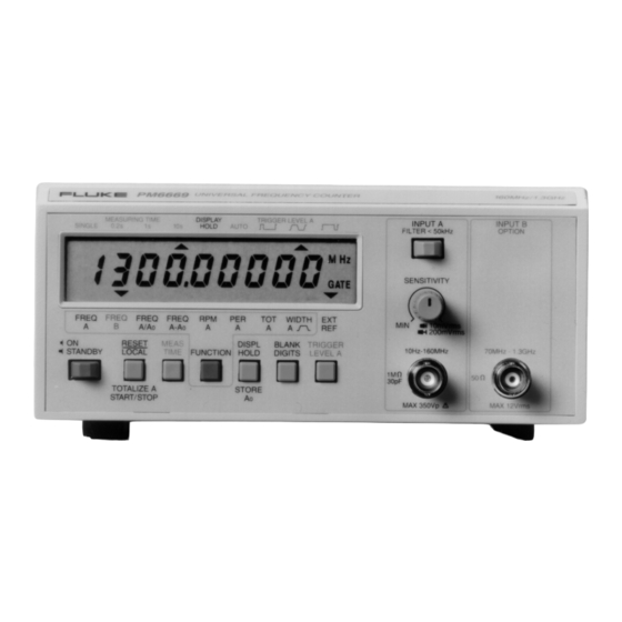
Page: 4 PRODUCT PRESENTATION PM 6669 UNIVERSAL FREQUENCY COUNTER 160MHz/1.3GHz MEASURING TIME TRIGGER LEVEL A DISPL INPUT A INPUT B SINGLE 0.2s HOLD AUTO FILTER<50kHz OPTION SENSITIVITY FREQ FREQ FREQ FREQ WIDTH A/Ao A-Ao 10mVrms 200mVrms RESET MEAS DISPL BLANK TRIGGER FUNCTION 70MHz - 1.3GHz... -
Page 6: Installation
Has the Frequency Counter been damaged in transport? 10MHz 0.5-15Vrms If it has, file a claim with the carrier immediately, and notify the Fluke sales & service organization to make repair or THERMAL FUSE IN MAINS TRANSFORMER replacement of the instrument easier. -
Page 7: Connecting External Reference
MTCXO, use a reference with an accuracy of 3*10 – Remove the cover from the counter. The PM 9691 oven-enclosed oscillator used in Fluke – Allow the MTCXO to adapt the new ambient tempera- counters version /.5. meet this requirement, if calibrated. - Page 8 INSTALLATION Page: 7 – Wait about 20 seconds, until the display shows 10.0000000 MHz. Now the oscillator is calibrated. – Switch OFF the counter and disconnect the 10 MHz ref- CALIB-button erence. Fit the cover. Figure 6 Location of the CALIB-Button. PM 6669 - OPERATORS MANUAL...
-
Page 9: Operating Instructions
Page: 8 OPERATING INSTRUCTIONS OPERATING INSTRUCTIONS Using the Frequency Counter CONTROL OPERATING THE DISPLAY GPIB-CODE CONTROL MEASURING TIME DISPL TRIGGER LEVEL A POWER, a two-position No control SINGLE 0.2s HOLD AUTO mechanical push-button. possible but D STAND-BY Pressed = ON, gives the same Released = OFF settings as... - Page 10 Try switching the Frequency Counter off and on Error 02 = Measuring logic error again. If error code 01 - 03 persists, call Fluke serv- Error 03 = Internal bus error ice. Look on the last page in this manual for Phone Error OF = Overflow in the counting registers No.
- Page 11 Page: 10 OPERATING INSTRUCTIONS CONTROL OPERATING THE DISPLAY GPIB-CODE CONTROL MEASURING TIME DISPL TRIGGER LEVEL A Move function cursor to FREQ B SINGLE 0.2s HOLD AUTO FREQ B FUNCTION FREQ FREQ FREQ FREQ WIDTH FUNCTION MEASURING TIME DISPL TRIGGER LEVEL A Move function cursor to Not bus SINGLE...
- Page 12 OPERATING INSTRUCTIONS Page: 11 FUNCTION AND RANGE HINTS AND COMMENTS Reciprocal frequency measurement of the signal at In- The cursor does not stop at FREQ B if no Input-B HF- put-B. input is installed. Range: 70 to 1300 MHz (PM 9608B) The counter divides the frequency on Input-A by a If you select this function without storing A constant, A...
- Page 13 Page: 12 OPERATING INSTRUCTIONS CONTROL OPERATING THE DISPLAY GPIB-CODE CONTROL MEASURING TIME DISPL TRIGGER LEVEL A Move function cursor to WIDTH A or SINGLE 0.2s HOLD AUTO WIDTH A PWIDTH A FUNCTION FREQ FREQ FREQ FREQ WIDTH FUNCTION MEAS TIME is operated MTIME <num>...
- Page 14 OPERATING INSTRUCTIONS Page: 13 FUNCTION AND RANGE HINTS AND COMMENTS The counter measures the positive pulse width of the If you are interested in the negative pulse width signal on Input-A. instead; first measure the period and make a note of Range: the result, then measure the pulse width and 100 ns to 200 000 000 s.
- Page 15 Page: 14 OPERATING INSTRUCTIONS CONTROL OPERATING THE DISPLAY GPIB-CODE CONTROL The TRIGGER One code for LEVEL A control is each trigger TRIGGER LEVEL A operated in the same level offset. way as the functions See below. control, see page 8. MEASURING TIME DISPL TRIGGER LEVEL A...
- Page 16 OPERATING INSTRUCTIONS Page: 15 FUNCTION AND RANGE HINTS AND COMMENTS The normal trigger level of the AC-coupled Input-A is It is often possible for the counter to trigger on 0 V. This is ideal for symmetrical signals like sine- unsymmetrical signals even though the symmetrical waves, since their average DC component is 50 % of triggering is selected, provided that the sensitivity is Vp-p.
- Page 17 Page: 16 OPERATING INSTRUCTIONS CONTROL OPERATING THE DISPLAY GPIB-CODE CONTROL RESET/LOCAL, a short X starts a new RESET press is enough for measurement. LOCAL Reset. When the remote indicator is on, a press will cause the counter to TOTALIZE A switch back to LOCAL, START/STOP i.e.
- Page 18 OPERATING INSTRUCTIONS Page: 17 FUNCTION AND RANGE HINTS AND COMMENTS When reset is depressed, the display and counting When the counter is controlled from the GPIB-Bus, registers are cleared. When reset is released, a new the LOCAL key can be disabled via the ’Local Lock measurement is started.
- Page 19 Page: 18 OPERATING INSTRUCTIONS CONTROL OPERATING THE DISPLAY GPIB-CODE CONTROL Pull the SENSITIVITY Not adjustable INPUT A SENSITIVITY knob to switch to AC from the bus. coupling. Depress the knob to switch to DC 10mVrms 200mVrms coupling. NOTE: The potentiometer controls the sensitivity when AC- coupled and Trigger Level when DC-coupled.
- Page 20 OPERATING INSTRUCTIONS Page: 19 FUNCTION AND RANGE HINTS AND COMMENTS For frequency-, period-, and ratio measurements: Set the sensitivity knob fully counter clockwise. Turn it until the input triggers. Select AC coupling and set the sensitivity so that the Continue turning to the 20 mV position, or to the hysteresis band of the Frequency Counter is about position where the display turns unstable due to noise.
-
Page 21: Battery Unit
If error code 01-03 per- Battery Care sists, call Fluke service. Look on the last page in this manual for Phone No. and address. The capacity of the rechargeable battery degrades if the counter is not powered by the battery frequently. -
Page 22: Gpib-Interface Operation
All the capabilities of the interface for the PM 6669 are The counter can receive programming instructions from explained below. If you want a complete description of the controller. L4 means the following functions: all GPIB-interface functions, read the ’Fluke Instrumenta- – Basic listener. tion-Systems Reference-Manual’. -
Page 23: Connecting The Controller
If everything is OK, the counter will identify itself as: PM6669/YZW/MN Giving the Counter an Address where: 4 if the counter has an HF-input, otherwise 0. The counter must have a unique address so that the 3 for MTCXO, otherwise 1 controller can communicate with it. -
Page 24: Two Ways Of Programming
GPIB-INTERFACE OPERATION Page: 23 Two Ways of Programming Syntax The simplest way of programming the counter is by What is a Programming Command? manually setting up the measurement you want from the front panel of the counter, then let the controller ask the A programming command consists of a header, address- counter how it is set up. -
Page 25: Selecting Output Separator
Page: 24 GPIB-INTERFACE OPERATION Order of Commands in a Program How to Select Function Message Standard Functions Normally, the programming commands in a program- Functions are selected by sending the appropriate func- ming message can be placed in any order. tion command to the counter, e.g. -
Page 26: Selecting Triggering
GPIB-INTERFACE OPERATION Page: 25 The Measuring-time cursor on the display will indicate Free-Run/Triggered 0.2 s for all programmed Measuring-times except SIN- The counter can work in two different ways: GLE, which will be indicated as usual. Free-Run, where it starts a new measurement as soon as the previous measurement is finished. -
Page 27: Service Request
Page: 26 GPIB-INTERFACE OPERATION Bus Triggering Status Byte ’X’ will always cause the counter to start a new measure- The counter sends its status byte to the controller on a ment. X will work as group execute trigger, GET. ’X’ must serial poll. -
Page 28: Output Mode
GPIB-INTERFACE OPERATION Page: 27 ing. This way the controller knows when it is possible to Important trigger the counter. Deci- Binary bits (X = mal* 76543210 don’t care) Comment Measuring result ready indicates that the measure- 00000110 XX0XX1XX Measuring start ment and calculation of the result is completed and that enable. -
Page 29: Output Format
Page: 28 GPIB-INTERFACE OPERATION Output Format High-Speed Dump The most time-consuming part of a measuring cycle is Normal calculating the result. The calculations limit the number When you select normal output format, the output will be of possible results/second to about 5, even when the as follows: Measuring-time is short. - Page 30 GPIB-INTERFACE OPERATION Page: 29 Hex-Digits JP000000000683 All 12 digits together represent register 3. ’J’ means that you must use formula J which is: −7 Reg . 3 ∗ 10 111111222222 = 000000000683 is the hex-contents of register 3. The reg- = 333333333333 ister contents must be converted to a decimal number and entered in the formula;...
-
Page 31: Bus Learn
Page: 30 GPIB-INTERFACE OPERATION Bus Learn Programming Data Out Any one of the queries used for Bus Learn can be used – Set the counter to LOCAL and select the functions you to ask the counter about its current setting, see ’Bus want from the front panel. -
Page 32: Summary Of Bus Commands
GPIB-INTERFACE OPERATION Page: 31 Bus Related Commands Summary of Bus Commands OUTM <number> Function Selecting Commands High- Output MTCXO FREQ A Frequency measurement on Input-A. <number> speed format compen- dump sation FREQ B Frequency measurement on Input-B. NORMAL RPM A Revolutions/minute on Input-A. -
Page 33: Programming Examples
Example of a result: this example. MEASURING TIME WILL BE ! DEMO PROGRAM DUMP MODE SELECTED BY HP85 (SINGLE)! ! PM6669 WITH HP85 AS ANSWER Y WHEN READY TO START! ! CONTROLLER ! DUMP MODE WITH FREE RUN ON CLEAR... - Page 34 ÁSK FOR AND PRINT PROGRAM DATA The following example runs on an IBM compatible PC PRINT "COUNTING SETTING:" equipped with Fluke PM 2201 GPIB interface. The instal- S$ = "FNC?" lation and starting up of the PC program is not de- GOSUB 520 scribed, only the application program.
- Page 35 This program prompts the user to input a programming This example runs on an IBM PC with an ‘IBM General sequence. The sequence is then sent to the PM 6669 Purpose Interface Bus Adapter’ instead of the Fluke and the corresponding measuring result is read. PM 2201 interface.
-
Page 36: Specifications
SPECIFICATIONS Page: 35 SPECIFICATIONS Mode: Single period measurement (SINGLE) or period aver- Measuring Functions age measurement (at 0.2, 1 or 10 s Measuring-times). Frequency A or B LSD Displayed: Range, 100 ns ( TIME < 100 SINGLE period measurement: 5 ∗ PERIOD ( TIME >... -
Page 37: Definitions
Page: 36 SPECIFICATIONS 100 ns ( TIme < 100 s ) LSD Displayed: Input specifications 5 ∗ WIDTH ( TIme > 100 s ) Input-A Frequency Range: NOTE: Triggering on 50% of amplitude will occur only if 0 Hz to 160 MHz the duty factor of the signal is 0.5. -
Page 38: General Information
SPECIFICATIONS Page: 37 AM Tolerance: 98%, minimum signal must exceed mini- Environmental Conditions mum operating input voltage requirement Temperature, Impedance: 50Ω nominal, VSWR <2:1 Operating: 0°C to +50°C Maximum Voltage Without Damage: 12 V , over- Storing: -40°C to +70°C load protection with PIN diodes. -
Page 39: Auxiliary Functions
Page: 38 SPECIFICATIONS matically corrected for the time-base frequency tempera- Displ Hold/Store A ture error, before being displayed. The DISPL HOLD/STORE A button has two functions: Oscillator Version: DISPL HOLD The result of the current measurement will Uncompen- MTCXO be frozen on the display. A new measurement starts sated when RESET button is pressed. - Page 40 SPECIFICATIONS Page: 39 The highest output rate is obtained at SINGLE Measur- Output Data Separator: Default separator at power-on ing-time. is LF. The separator can be programmed to be any non printable ASCII-code with decimal equivalent 0-31, ex- Output Time for Measuring Data; cept 27 (ESC).
-
Page 41: Ordering Information
Page: 40 SPECIFICATIONS That second instrument can be a Philips PM 2534 to 35 Options and Accessories or a FLUKE 8840 Digital Multimeter, or another PM 9604 GPIB-interface PM 666X counter. PM 9605 Battery unit High Stability Time-Base PM 9607... -
Page 42: Checking The Sensitivity Of Counters
APPENDIX 1 Page: 41 APPENDIX 1 High-Impedance Inputs (1 MΩ) Checking the Sensitivity of Counter Oscilloscope Counters > under test 350 MHz Signal source Introduction The sensitivity of a counter is normally specified as the 50 ohm 50 ohm minimum signal voltage on which the input of the counter will trigger correctly. - Page 43 Page: 42 APPENDIX 1 – – Connect it directly to the input of the counter. Check that the reading is the same as, or less than, the sensitivity level in the counter specifications. – Check that the counter is operating correctly. Method 2 If you don’t have a calibrated signal-source Use either of the following methods...
-
Page 44: Index
INDEX Page: 43 INDEX Device clear ........22 GPIB code ........10 Device Trigger.........22 Selecting ........10 Abnormal bit Dimensions ........37 Specification ......35 See Status byte Display Function Specification......37 GPIB code ........8 Selecting........18 Display hold Selecting ........8 Accessories........40 Operating the button .... - Page 45 Page: 44 INDEX Specification......36 From GPIB ........24 Output ........24 Input B Specification......35 Service request ......21 Operation ......... 16 Period A GPIB .........26 Specification......36 GPIB code.........10 Short output format Input separator Selecting ........10 GPIB .........28 GPIB......... 23 PM 2201 Slope Input-A BNC-connector GPIB example......33...
- Page 46 Service Center Service Center Philips S.A. H,llenique Kaltim - Zagreb Av. Interlagos North Lacarra 234 Fluke Sales & Service Manager Fluke Sales & Service 3493 - Campo Grande Buenos Aires CP 1407 15, 25th March Street Draga 8 04661-200 Sao Paulo S.P.
- Page 47 +966-2-6610558 P.O. Box 6054 Bldg. Customer Support Services Etterstad 1-1-11 Hamamatsucho Science Park Eindhoven 5108 Singapore N 0601 Oslo Minato-ku, Tokyo 105 5692 EC Son Fluke Singapore Pte., Ltd. Phone:+47-22-65-3400 Phone:+81-3-3434-0188 Phone:+31-40-644310 Service Center Fax: +47-22-65-3407 Fax: +81-3-3434-0170 Fax: +31-40-644321...
- Page 48 E-Mail: wwitko@wz.fluke.com The Netherlands Service Center - Everett Phone:+31-40-644265 Building #4 United Kingdom Fax: +31-40-644260 1420 - 75th St. S.W. Fluke United Kingdom Ltd. Everett, WA 98203 Customer Support Services All other countries Phone:+1-206-356-5560 Colonial Way Fluke Corporation Fax: +1-206-356-6390 Watford P.O.
Need help?
Do you have a question about the PM6669 and is the answer not in the manual?
Questions and answers