Table of Contents
Advertisement
Advertisement
Table of Contents

Related Manuals for HP 7475a


Summary of Contents for HP 7475a
- Page 1 H EWLETT PACKARD HP 7475A Graphics Plotter...
- Page 2 HP 7475 A OPE RAT ION Graphics AN D Plotter IN TERCONNECTION MANUAL...
- Page 3 Getting Hel p Hewlett-Packard has support services available to help you in case you have a problem with your HP 7475A graphics plotter. Following are suggestions of places to turn for this support. Before you call for customer support, make sure you do the following.
- Page 4 (RS·232·C Identify the software name and version you are currently using. • The HP 7475A Assist service is available from 7 am - 4 pm (Mountain Standard Time), Monday through Friday. (208) 323-2551 Should the plotter require service, please refer to the last section Chapter 1 for shipping instructions.
-
Page 5: Table Of Contents
What Is a Program? ........2·2 What Programming Languages Do I Use? ....2· 3 AGL (A Graphics Language) ......HP-GL (Hewlett·Packard Graphics Language) ....2·3 Introduction to the Plotter Coordinate System ....2·4 Coordinate System Orientation ...... - Page 6 Apple* IIe or II Plus Computer (RS·232·C Interface) ... 3·7 Interconnection Instructions ....... Running the Test Program ........ 3·9 Apple lIe or 1I Plus Computer (HP·IB Interface) ....3-10 Interconnection Instructions ....... 3-10 Running the Test Program ........ 3-11 Apple Computer (RS-232·C Interface) 3-13 •...
- Page 7 Interconnection Instructions ....... 3 ·17 V erifying Communication 3-19 • • HP Series 200 Personal Technical Computer (HP- I B Interface) ......... 3 -20 Interconnection Instructions 3 -20 • • Running the Test Program ........ 3 -21 HP Touchscreen Personal Computer (HP 150) ( RS-2 3 2-C Interface) ....
- Page 8 .. . ";: :� ',';;.� .", .
-
Page 9: Chapter 1: Owner's Information
Introduction This manual contains general information to familiarize you with the capabilities and operation of the HP 7475A Option 001 and Option 002 Graphics Plotters. The Option 001 plotter is equipped with the R.S-232-CI CCITT V.24 Interface. The Option 002 plotter is equipped with the Hewlett-Packard Interface Bus (HP·IB), which conforms... -
Page 10: Understanding Manual Conventions
Carefully inspect the plotter and accessories for any physical damage sustained in transit. Notify the nearest HP Sales and Support Office or authorized HP dealer and file a claim with the carrier if the unit is received in a damaged condition. -
Page 11: Accessories Supplied
Accessories Supplied The following items are supplied with each 7475A plotter: Item Quantity Part Number 07475·90002 Operation and Interconnection Manual 07475-90004 Reference Card 5958-2664 Customer Survey Card 5957-2658 HP Field Repair Centers 5955-7441 HP Sales and Support Offices Power cord (appropriate cord supplied, based on origin of sales order) 5061·5080... -
Page 12: Input Power Requirements
Consumption: Line Voltage Selection The 7475A is shipped from the factory with the line voltage set to the nominal value for the area specified as the shipment's destination. The voltage selected for the plotter is identified in the recessed window on the rear panel. -
Page 13: Fuse Protection
To avoid the possibility of injury, disconnect the ac power cord before installing or replacing a fuse. The 7475A is factory equipped with a fuse appropriate to the factory-set line voltage. The selected line voltage and the corresponding fuse rat·... - Page 14 United States. NEMA6-15P Part Number 8120-0698; 250 V, IS A, 1 '" plug rating. UL approved in United Stares. HP Part Number 8120-2104; 250 V, 10 A, 1 '" SEV 1011 plug rating. For use in Switzerland. DHCK-107 Part Number 8120-2956; 250 V,10 A,I '"...
-
Page 15: Operator Maintenance
Operator Maintenance There are no operator·serviceable parts inside the HP 7475A plotter. Maintenance which can be performed by the operator is limited to maintaining the appearance of the plotter. All other maintenance must be performed by qualified service personneL Refer to the Shipment paragraph for instructions on how to obtain servicing assistance. -
Page 16: Pen Carousel Cleaning
Hewlett-Packard Sales and Support Office . If your plotter is being returned to Hewlett-Packard for service, contact your nearest HP Field Repair Center for complete shipping instructions . In countries without Field Repair Centers, contact your HP Sales and Support Office . - Page 17 Plots or any other materials that help illustrate the problem area. If purchased through an HP dealer, a copy of the sales slip or other proof of purchase to establish the warranty coverage period. Serial number of your plotter (located on rear panel).
-
Page 19: Chapter 2: Plotter Operation
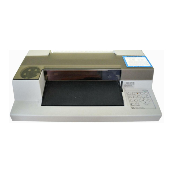
Chapter Plotter Operation Introduction In this chapter you will learn about programming languages, the functions of each control and indicator, the plotter's coordinate system, and how to rotate the coordinate system. You will also learn how to load pens and paper and hQw to determine that the plotter is functional. Major Feature Locations The following illustration shows the locations of the major operating features. -
Page 20: Introduction To Programming Languages
PAPER CAROUSEL LEVER lI1Innl:mu:: ,UIIII1II1I U 1111111111 till III IIII I� tllltl � REAR SERIAL LINE LINE VOLTAGE! NUMBER POWER PANEL FUSE RATING SOCKET (TYPICAL) LABEL Major Feature Locations Introduction to Programming Languages What a Program? A program is an organized set of instructions that tells your computer and plotter to accomplish certain tasks. -
Page 21: Agl (A Graphics Language)
They consist of English words that are usually followed by numeric parameters. These statements describe their graphics plotting function and instruct the computer to send HP-GL instructions to the plotter. One AGL statement often performs a task that would require several HP-GL instructions to perform. -
Page 22: Introduction To The Plotter Coordinate System
X-axis and the fifth positive grid line along the Y·axis. These coordinate values are used as parameters in HP-GL instructions to move the pen to any given point in the plotting area. -
Page 23: Coordinate System Orientation
Refer to Rotating the Coordinate System in this chapter. NOTE: The power-up default input window is coincident with the hard clip limits. The size of the input window can be changed using the HP .• GL instruction, lW, to programmatically limit the pen's motion... - Page 24 ---------- --- - ---.. PI IDEFAULT) HAAO-CUP LIMITS (OEFAUL T) P2 • Default Orientation of Plotter Coordinate System (BI A3 Paper) Maximum Plotting Ranges Maximum Plotting Range Paper Size Settings (Plotter V nits) Selected VS/MET A4/A3 Paper Size X-Axis V-Axis 0·10365 0·7962 (8.5...
-
Page 25: The Scaling Points Pi And P2
X and Y) or isotropic (equal in X and Y) and each axis can have a different n umber of user units. For example, the HP - GL instruction SCO , 12,0, 1 000 scales the PI/P2 frame into 1 2 user units in the X-axis, representing months, and into 1000 user units in the Y-axis, represent... -
Page 26: Agl Scaling
VUB (user units), With this system, AGL programs can produce plots within any area defined by PI and P2 without modifications to the program. Refer to your HP computer documentation for the information you need to program in AGL. -
Page 27: Setting The Scaling Poin T S
Setting the Scaling Points The locations of scaling points PI and P2 can be changed manually from the front panel or programmatically with the Hp· G L instruction I P. Refer to the Interfacing and Programming Manual for instructions on how to set the scaling points programmatically. -
Page 28: Squeezing The Scaling Area ''''''
Preparing Equal-Sized Plots Squeezing the Scaling Area P lIP2 When a frame is established within the plotting area, and then Pl!P2 PI is moved so that intersects the hard·clip limits, a new frame is established at the point of intersection_ This feature is illus trated as follows: PlIP2 DETAIL A:... - Page 29 DETA I L "A" LIMITS DETAIL "8" HAAD-ClIP LIMITS DETA I L "C" OLD Pl LOCATION NEW Pl HAAD-CLlP LOCATION LIMITS Squeezing The Scaling Area PLQITER OPERATION 2-11...
-
Page 30: Rotating The Coordinate System
The rotate function can be manually invoked from the front panel, ENTER + FAST using the button combination, or programmatically, using the HP·GL instruction, RO . The only difference is the rotated locations Ll (O , O OAIGIN) r - - -... - Page 31 The input window can be expanded to the hard clip limits and PI and P2 can be defaulted to the rotated default coor dinate values using the HP-GL instructions, IW and lP, without parameters. Whether invoked manually or programmatically, the physical size and location of the hard-clip limits are not affected by the rotate function.
-
Page 32: Controls And Indicators And Their Functions
Configuration controls consist of two switches on the rear panel. These switches determine the power-up default paper size, hard-clip limits, and PI/P2 coordinate values. The switches are common to both HP-IB and RS·232·C interface options. Interface controls establish the conditions under which communication between the plotter and computer will occur. - Page 33 SIZE. ERROR PCN UfD " D D VIEW 741!1'" PLOTTER W�WUY T · ".C;�"\O FRONT PANEL (2 - 10) REAR PANEL (14 - 19) RS-232-C/CCITT V.24 REAR PANEL (20 - 22) HP-IB Operator Controls PLO'I�'ER OPERATION 2·15...
- Page 34 The pen holder moves to the right side of the platen. b. Aborts any in-process HP·GL vector or area fill command. PAPER Returning the paper loading lever to the...
- Page 35 ERROR it indicates the plotter has detected an 1/0 error, a paper moving error, or an HP·G L error for which the error mask has been set. For a description of errors, refer to instructions IM, OE, and ESC . E in the Interfacing and Programming Manual.
- Page 36 The plotter assumes a new piece of paper is loaded and the pen holder lifts and moves to the extreme right. c. The equivalent of executing an Hp·GL DF instruction establishes default conditions. d. PI and P2 are set to their default coordi·...
- Page 37 Pressing this latching pushbutton turns VIEW VIEW on the light, suspends plotting, raises ERROR the pen, and moves the paper so it is fully extended. In this state you can manually sub stitute pens and view the entire plotting area. Pressing the push button again turns off VIEW...
-
Page 38: Rear
(e/A3 AlA4) receives the HP·CL instruction, DP. This blink ing light indicates the digitizing mode is ini· tiated and the pen should be moved to the point to be digitized. If is then pressed,... - Page 39 (endline operating environment). In this position, the plotter powers up in the programmed "on" operating state. The plotter will respond to all HP·GL and escape sequence instructions, except the ESC . } or ESC . plotter "off' instructions.
- Page 40 NOTE: The plotter's switch must be ..lINE in order to have any communication between • the terminal and the computer. This rocker switch is used in com US/MET bination with the rocker switch to select A4/A3 one of four possible default paper sizes with the appropriate sized hard-clip limits and de...
-
Page 41: Option 002 (Hp·ib)
2400 4800 9600 Option 002 (HP-I B) This 24-pin Hp·IB connector is used to connect the plotter to a host computer or other Hp·IB device. These two rocker switches US/MET A4/A3 are common to the Hp·IB and RS·232·C inter face options. Refer to the Option 001 (RS-232-CI . -
Page 42: Setting Up The Plotter
- - - - - - - - - - - - - - - - - - - - ---, ...1 Reserved for HP Desktop _ _ _ _ _ _ _ _ _ _ _ _ _ _ _ _ _... -
Page 43: Choosing The Correct Pen And Medium
describe these procedures and include instructions for choosing the correct pen and medium combinations. Choosing the Correct Pen and Medium To obtain plots of the highest quality, it is important to use pens and media that matched to your application. Two types of liber-tip pens recommended: one for plotter paper and one for transparency film. -
Page 44: Loading The Plotting Medium
Loading the Pens and the Carousel Loading the Plotting Medium The plotter is designed to be used with HP paper and pens. Use of other paper may cause poor line quality. For best results, order papers listed under Accessories Available. To load paper, proceed as follows: Set the switches o n the rear panel to the approp... - Page 45 NOTE: If necessary, snap the spacer off the shaft, slide the pinch wheel to the proper position, and snap the spacer back onto the shaft. • Pinch Wheel Position for A and Size Paper Pinch Wheel Position for A4 and A3 Size Paper Move the paper loading lever to the position.
-
Page 46: Turning On The Power
Loading AI A4 Size Paper Loading BI A3 Size Paper Turning On the Power The plotter performs an initialization cycle when ac power is applied. The initialization cycle sets all plotter functions to their default condi tions (conditions assumed by the plotter in the absence of an actual instruction). - Page 47 After power-up initialization is completed, the first pen select command will cause the carousel to be initialized. The pen select command can be invoked programmatically with an Hp·GL command or manually with pushbuttons. Carousel initialization consists of backing the carousel around to its stop before it is advanced the position that corresponds with the pen select command.
- Page 48 Power· Up Default Conditions Equivalent Condition Function Instructions Absolute (plotter units) Plotting mode Rotation o degree (default orientation) Solid line Line type Line pattern length L1'n,4; 4% of the diagonal distance between PI and P2 Pcn state Pen velocity 38.1 cm/s (15 in.!s) Scaling Off (XY coordinates in plotter un its) Input window...
-
Page 49: The Demonstration Plot/Confidence Test
The Demonstration Plot/Confidence Test The plotter has a built-in demonstration plot that will run on any size paper. However, the plot is centered only on A-size paper and approxi· mately centered on A4-size paper. Therefore, if the plotter is set for B- or A3-size paper, the plotter will automatically switch to the corresponding smaller paper size before ru�ning the plot. - Page 50 Floltt· .. ()pt'ratiol1 G R A P H I C S I M P R O V E S C O M M U N I C A T I O N ::;; t'"1 � '" SALES REVENUE D I STR I B U T I O N ."...
- Page 51 NOTES...
-
Page 53: Introduction
HP 7475A. IWad the manual that describes the communications eqnip ment for your computer, and then detennine how information is sent and received. Next, refer to either Chapter 9 or 10 in the HP 7475A Interfacing and Programming Manual (depending on which interface you're using) to get a better understanding of how information is sent and received by the plotter. -
Page 54: One Listed
If Your System Configuration Is Different From the One Listed . . . There are many variables in computer systems. Often substituting one piece of hardware or software for another can cause communication problems. Therefore, if you're going to make substitutions, be aware that these may affect the operation of the system or the communication verification program. - Page 55 Make sure the output port connected to the plotter is the one specified by the software. Is your plotter working properly? • Chapter 2 of this manual describes how to perform the HP 7475A plotter confidence test. • Make sure the switches on the back of the plotter are set properly.
-
Page 56: Interconnection Instructions
25-pin male connector with asynchronous communication HP 24542G adapter using a 9-pin male connector HP Vectra, ES/l2, QS/16, RS/20 with HP 24540A or HP 24541A card HP 24542G using 9-pin male connector with the HP 2454lA dual serial card HP l 7255M... - Page 57 NO PARITY. SETTING OPERATING ENVIRONMENT. OF 82 1 8 IRRELEVANT. Connect the plotter to the computer. The following illustration shows an HP Vectra PC. Be sure you are using the correct cable for your computer and plotter . Monitor power...
-
Page 58: Testing Communication With Basic
Testing Communication without BASIC To test the computer/plotter interface without using BASIC, turn on your computer and plotter, load pens and paper, then follow these steps. At the DOS prompt, type the following (substitute COM2 for COM1, if necessary) and press ENTER. MODE COM1: 9600 , N , 8 , 1 , P This sets the RS·232-C port for 9600 baud, no parity, data bits,... - Page 59 A pp le lIe or Plus Com p uter (RS-232-C Interface) Computer Cable Apple lIe or 11 Plus HP 17355 M Apple Super Serial Card (Apple Part No. A2BOO44) Interconnection Instructions Install the Apple Super Serial Card as follows (refer to your com...
- Page 60 With your plotter and computer turned off, connect the plotter to the computer using the RS-232-C cable as shown below. Either end of the cable can be connected to the plotter or the connector on the installed serial card (port #2). The following illustration shows an Apple IIe.
- Page 61 50 PRINT " L B " , I D' , · COMMUN ICATION OK " , CHR$( 3 ) 70 PRINT · P A0 . 0 , SP0 , " B0 PR.0 I N.0 90 END Your plotter will select pen #1 and print 7475A COMMUNICATION PWITER INTERCONNECTION...
- Page 62 Install the Apple IEEE-488 Card into Slot #3 (refer to your com puter documentation for details). With your plotter and computer turned off, connect the plotter to the computer using the HP-IB cable as shown below. The foIlowing illustration shows an Apple IIe. MonItor...
- Page 63 Set the HP-IB switches on the rear panel of your plotter as shown in the following diagram. Your plotter checks the switch settings only when you turn it on, so be sure the plotter is turned off before changing switch settings.
- Page 64 Apple Unit Apple Modem Eliminator Cable (Apple Part No. A3M0019) and HP 17355M Interconnection Instructions With your plotter and computer turned off. connect the plotter to the computer using the RS-232-C and modem eliminator cables shown below. Either end of the RS-232-C cable can be connected to the plotter.
- Page 65 Set the switches on the rear panel of your plotter as shown in the following diagram. Your plotter checks the switch settings only when you turn it on, so be sure the plotter is turned off before changing switch settings. SET TO US POSITION FOR A AND B PAPER.
- Page 66 PRI N T ' 1 , " LBCOMMUNI CATI O N O K " +CHR$ ( 3 ) PRINT 1 1 , " PAO, O ; 5PO ; " Your plotter will select pen #1 and print 7475A COMMUNICATION 3-14...
-
Page 67: Interconnection Instructions
Apple Macintosh/Macintosh Plus/II/SE (RS-232-C Interface) Computer Cable Apple Macintosh Computer HP 92219M Apple Macinl<lsh Plus HP 17302A Apple Macintosh 11 HP 17302A Apple Macinl<lsh SE HP 17302A Interconnection Instructions Turn off your plotter and computer equipment. Set the switches on the rear panel of your plotter as shown in the following illustration. - Page 68 60 PRINT n I , " P A 0 , 0 ; S P 0 " 70 END Your plotter selects pen #1 and prints 7475A PLOTTE R OK. NOTE: If you not using BASIC, a plotter driver is required to Macintosh computer with the plotter.
-
Page 69: Commodore Amiga Personal Computers (Serial Interface)
Commodore Amiga Personal Computers (Serial Interface) Computer Cable 17255D Amiga 500 1000 17255 M Amiga (or 13242G) 17255 D Amiga 2000 Interconnection Instructions With your equipment turned off, use the cable to connect the plotter to the computer's serial port. (The following illustration shows Amiga 2000 . - Page 70 Set the switches on the rear panel of your plotter as shown in the following diagram. Your plotter checks the switch settings only when you turn it on, so sure the plotter is turned off before changing the switch settings. SET TO US POSITION FOR A AND B PAPER OR TO MET FOR A4 AND A3 PAPER.
-
Page 71: Erifying Communication
Verifying Communication From Workbench, open the Utilities drawer. Start the Notepad application by double-clicking on the Notepad icon. Type the following HP-GL commands (uppercase only) into Notepad. I N ; SP1 ; SP2 ; SP0 ; Select Print then Print to send the commands to the plotter. -
Page 72: Hp Series 200 Personal Technical Computer (Hp- I B Interface)
Interconnection Instructions With your plotter and computer turned off, connect the plotter to the computer using the HP-IB cable shown. Either end of the cable can be connected to the plotter or computer. The illustration below shows an HP Model 216 connected to the plotter. -
Page 73: Running The Test Program
; " LB " & I O$& " COMMUN I C A T I O N O K " &CHR$( 3 ) 50 OUTPUT 70S ; " PA0 . 0 ; SP0 ; " 60 END Your plotter will select pen #1 and print 7475A COMMUNICATION PLOTT E R INTERCONNECTION 3-21... -
Page 74: Hp Touchscreen Personal Computer (Hp 150) ( Rs-2 3 2-C Interface)
HP Touchscreen Personal Computer Interface) (HP 150) (RS-232-C Cable Computer HP 17255M or HP Touchscreen or Touchscreen MAX Personal Computer (or HP 150 HP 13242G System with Dual Disc Drive) Interconnection Instructions With your plotter and computer turned off, connect the plotter to port 2 of the computer using the RS·232-C cable... - Page 75 Set the switches on the rear panel of your plotter as shown in the following diagram. Your plotter checks the switch settings only when you turn it on, so be sure the plotter is turned off before changing switch settings. SET TO US POSITION FOR A AND B PAPER, SET TO A4 FOR A AND A4 PAPER...
-
Page 76: Running The Test Program
" L B " ; I D$ ; " COMMUN I CA T I ON O K " +CHR$ ( 3 ) 90 P R I N T 1 1 , " P A0 , 0 ; SP 0 ; " 1 00 END Your plotter will select pen #1 and print 7475A COMMUNICATION 3-24 PWITER INTERCONNECTION... -
Page 77: Hp Touchscreen Personal Computer (Hp 150 )
System with Dual Disc Drive) Interconnection Instructions With your plotter and computer turned off, connect the plotter to port 2 of the computer using the HP-IB cable as shown below_ Either end of the cable can be connected to the plotter or computer. HP-IS... - Page 78 START APPUC b. Touch the field, then use the key to select NEXT CHOICE PLT, HP·IB 5. Touch to save the configuration. SAVE CONFlG c. Press key to return to P.A.M. EXIT CONFlG Running...
- Page 79 Set the plotter switches on the back panel as shown by the following diagram. SET TO us POSITION FOR A AND B PAPER OR TO MET FOR A 4 AN O A 3 PAPER. SET TO A 4 FOR A AND A 4 PAPER OR TO A3 FOR B AND A 3 PAPER.
- Page 81 The chemical reaction between the pens and media is tested to ensure that fading and color changes are minimized. The smoothness of HP paper reduces abrasion on pen tips and produces a sharp, crisp ink line.
- Page 82 Fiber-tip pens will last at least 30 days stored in the carousel. However, if you do not plan to plot for several days, remove the pens from the carousel and cap them to ensure a longer pen life. Remove drafting pens and cap them immediately after use to prevent drying and clogging.
- Page 83 Internal airflow is Clean the pen. between the point obstructed or vent and adaptor. is clogged. Pen tips wear out Film surface is Use HP film. rapidly. abrasive. Lines look Pen tip is If the tip is not wavy. damaged.
-
Page 84: Double-Matte Polyester Film
Symptoms and Solutions (Continued) Problem Possible Cause Solution Ink fades or The ink is old. Use a new bottle separates. of ink. Replace the boot. Boot is deterio- Ink was diluted rating. with acetone. Dilute ink with distilled water, not acetone. Media You can use non·glossy plotter paper, glossy plotter paper, transparency plotter film, and double-matte polyester film with your plotter. -
Page 85: Fiber-Tip Pens
Combining Pens and Media U se the followin g ta ble to select the types of pens and m e d ia that work best tog ether and fi t your app l ication . Th e reco mmen d e d plotti n g speed ( i n centim etres per second ) is l iste d for each com bination . - Page 86 NOTES...
- Page 87 S eco n dary Tra n smit Da t a " S BA S econ dar y Re c eive Data " S BB 108 .2 Data Tenninal Read y wired only in used in 'Pins 14 and 16 the Y-cable (Part No. HP 17455A) eavesdrop configurations. A·1 RS-232-C INTERFACING...
-
Page 88: A-Irs-2 3 2-C Cable Schematics
RS-232-C Cable Schematics The following cable schematics are for Hewlett-Packard cables. Connector Type (25-pin) Computer End HP Part Number Plotter End male female 17255D male male 17255M 13242G' ·Symmetrical; either end may connected to the plotter. Other pins connected. in the... - Page 89 Connector Type Plotter End HP Pari Number Computer End 17302A male (25-pin) male (8�pin mini din) RS-232-C INTERFACING...
- Page 90 Connector Type (25.pin) HP Part Number Plotter End Computer End male female 173550 • male mate 17355M / - , • • • • • • Symmetncal; either end may be connected to the plotter. • RS-232-C INTERFACING...
- Page 91 Connector Type (25-pin) HP Part Number Plotter End Computer End 17455A male male (computer) female (terminal) Computer Terminal 4, 5, (pins through are directly connected between the computer and lerminal connectors) ilS-232·C INTER,'ACING...
- Page 92 Connector Type Plotter End Computer End HP Part Number male female (25-pin) 24542G (9-pin) Connector Type HP Part Number Plotter End Computer End male male 92219M (25-pin) (9-pin) RS-232-C INTERFACING...
- Page 93 1·3 Apple lIe/lI Plus Computer (HP·IB), plotter and ... . 3-20-3-21 Apple lIe/lI Plus Computer (RS-232·C), plotter and ..3-18-3-19 Apple IIC Computer, plotter and .
- Page 94 Subject Index (Continued) C (Continued) Coordinate system Cartesian Cartesian coordinate system 2- 6 default orientation of ........" origin, location of 2·5 •...
-
Page 95: Hp V Ectra, Es/12, Qs/16, And
Grounding, requirements for HP 150 Computer (HP-IB) ....... . . 3-25-3-26 HP 150 Computer (RS-232-C) . - Page 96 Option 001 RS-232-C Option 002 HP-IB P1/P2 positions also Scaling Points automatic postioning and ........2-9 default positions for .
- Page 97 Subject Index (Continued) (Continued) Paper also Me<lia glossy plotter ..........4-4, 4·5 holding 2·16.
- Page 98 ..........2-3 selecting a see HP·GL HP-GL introduction to .
- Page 99 Squeezing the ........2-10-2-11 HP-GL...
- Page 100 NOTES...
- Page 101 HEWLETT PACKARD 11 1 11 1 1 111 1 1 1 1 11 1 11 1 1 1 1 1 1 1 1 111 1 1 111 1 1 111 1 1 Manual Part Number: 07475-90002 Printed in U.S.A.. September 1990...
Need help?
Do you have a question about the 7475a and is the answer not in the manual?
Questions and answers
Can a HP50g calculator communicate with a HP 7475 Plotter?
The HP 7475A plotter communicates using the Hewlett-Packard Graphics Language (HP-GL) and supports both GPIB and RS-232 serial connections. The HP 50g calculator has an RS-232 serial port, which means it could potentially communicate with the HP 7475A if properly configured. To achieve this, the correct baud rate, data format (e.g., 9600 8N1), and HP-GL commands would need to be used. However, additional adapters or cables might be required to match the physical connections.
This answer is automatically generated